manuals.online logo
Brands
  1. Home
  2. •
  3. Brands
  4. •
  5. CAME
  6. •
  7. Security Sensor
  8. •
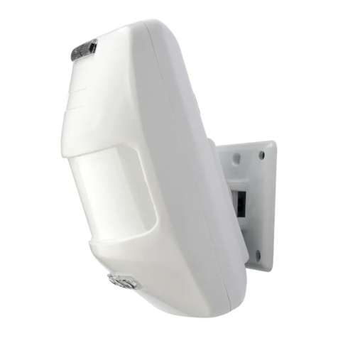
  9. CAME Security SIR215 User manual

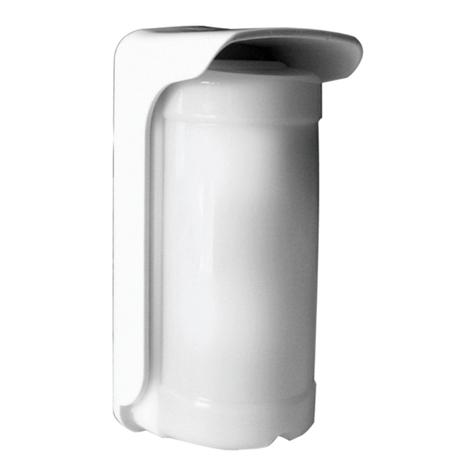
CAME Security SIR215 User manual

Manual code 119RV45 - version 1.0 - 03/2011
© CAME cancelli automatici s.p.a. - The data and information reported in this installation manual are susceptible to change at any time and without obligation to notify users.
5°C
50°C 110 x 60
x 46 mm 85 g
IP 30
+
-
2M1M
5
4
1 1
3
2
6
12°
36
2,10 m
󱵤
󱵢
󱵥
󱵦
󱵣❶
❸
❷
❺
❹
④
SIR215
Securityline
Manual code 119RV45 - version 1.0 - 03/2011
© CAME cancelli automatici s.p.a. - The data and information reported in this installation manual are susceptible to change at any time and without obligation to notify users.
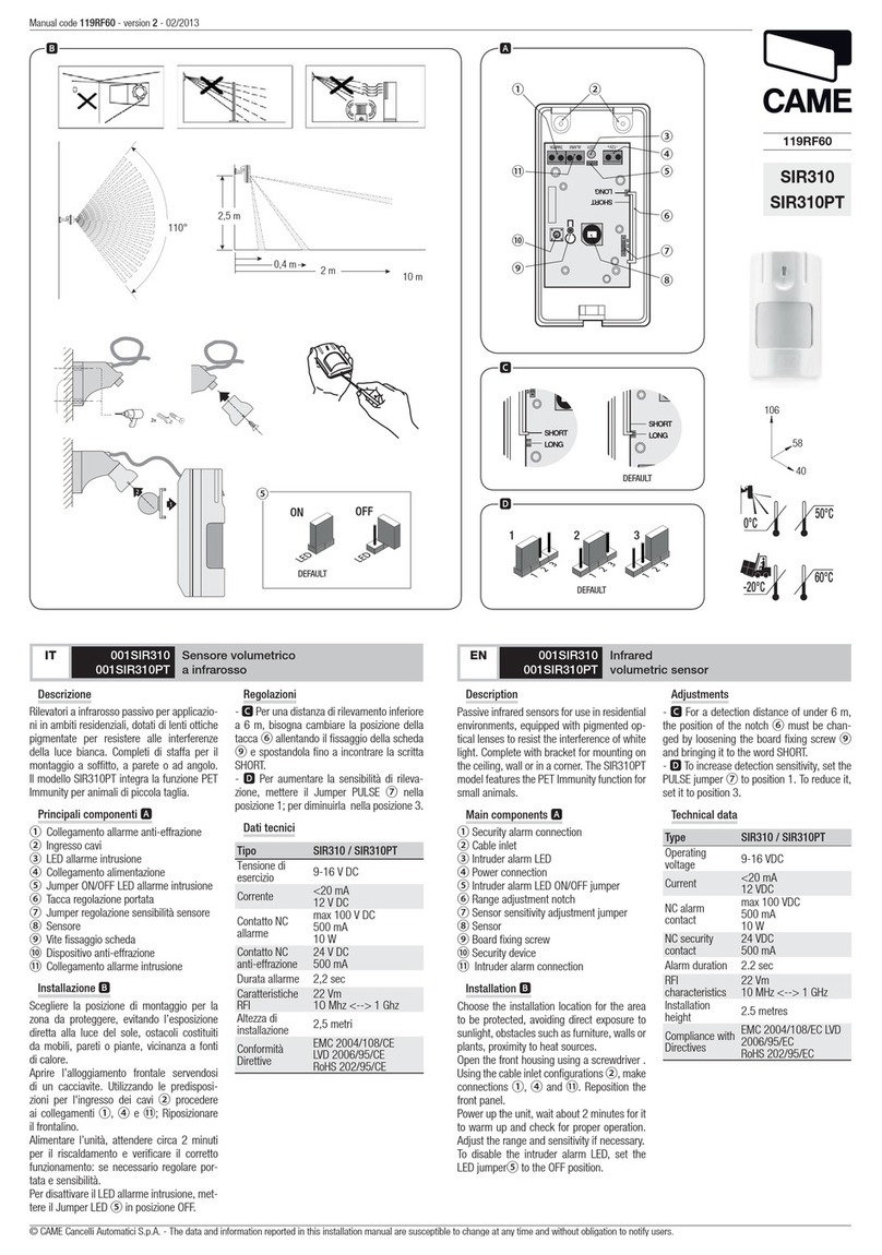
Sensore volumetrico per ambienti interni, a raggi infrarossi passivi.
DESCRIZIONE SCHEDA 󱵢
Morsettiere1. Sensore a infrarossi2. Regolazione infrarossi3. Jumper abilitazione Led4. Led di segnalazione allarme5. Dispositivo anti manomissione6.
INSTALLAZIONE
VERIFICHE PRELIMINARI
Prima di installare il sensore, accertarsi che nell’ambiente non ci siano cause
che possano alterare il buon funzionamento del sensore, per esempio: fonti
dirette di calore, luce solare diretta, presenza di animali nell’area protetta.
Il sensore deve essere posto ad una altezza di circa 2,1 m e con una
inclinazione che, per la massima copertura, deve essere di 12° 󱵣.
MONTAGGIO
Fissare lo snodo alla parete tramite i 4 fori predisposti nella staa• posteriore ❶(se necessario staccare anche la controstaa ❷).
Orientare il sensore nella posizione voluta e bloccarlo (con l’inclinazione• di 12°) stringendo con un cacciavite la bussola in ottone ❸.
Passare il cavo secondo la modalità prevista• 󱵤󱵥.
Rimuovere il coperchio del sensore• ❺e togliere la scheda elettronica.
Fissare il fondo del sensore• ❹allo snodo dopo aver passato il cavo
nell’apposita fessura.
Rimontare la scheda elettronica e collegare il cavo dell’alimentazione• (morsetti + e -). Rimettere il coperchio al sensore.
IT 001SIR215 Sensore volumetrico a infrarossi
TEST E REGOLAZIONI
Dare alimentazione al sensore e procedere con test e regolazioni solo dopo
un paio di minuti per fare in modo che il sensore si stabilizzi.
Regolare con il trimmer ③la sensibilità di rilevazione degli infrarossi 󱵦.
L’accensione del Led rosso ⑤, indica che l’allarme è attivato.
NB: è possibile escludere il sensore collegando il morsetto TC a una tensione
positiva +12V.
SIR215 è provvisto anche di un contatto anti manomissione ⑥normalmente
chiuso (TAMPER). Se il contenitore viene aperto, il contatto attiva l’allarme.
DATI TECNICI
Tensione di alimentazione 12 V (9÷16 V)
Consumo max 15 mA
Copertura volumetrica 110°, portata 15 m
Portata del contatto di allarme 24 V - 50 mA
Portata del contatto di tamper 24 V - 100 mA
Durata minima allarme 2 s
Umidità relativa max (senza condensa) 80%
Volumetric passive infrared indoor sensor.
CARD DESCRIPTION 󱵢
Terminals1. Infrared sensor2. Infrared adjusting3. LED clearing jumper4. Alarm notification led light5. Tampering-proof device6.
INSTALLING
PRELIMINARY CHECKS
Before installing the sensor, make sure the room is free of any interferences
that may alter the proper functioning of the sensor, for example: direct
sources of light, direct sun light, any animals in the protected area.
The sensor should be placed at about 2.1 m high and angled at 12° to provide
maximum coverage. 󱵣.
ASSEMBLY
Fasten the joint to the wall using the four pre-punched holes on the back• bracket. ❶(if necessary also detach the counter-bracket ❷).
Aim the sensor in the required direcntion and lock it (at a 12° angle) by• tightening the brass bushing ❸.
Pass the cable through as shown• 󱵤󱵥.
Remove the sensor cover• ❺and remove the electronic card.
Fasten the sensor bottom• ❹to the joint after passing the cable through
the apposite hole.
Reassemble the electronic card and connect the power cable (terminals• + and -) Replace the sensor cover.
EN 001SIR215 Volumtric infrared sensor
TESTS AND ADJUSTMENTS
Power up the sensor and proceed with the test and ajustments only after a
few minutes, so that the sensor has time to stabilise itself.
Adjusting by trimmer ③the detection sensitivity of the infrareds 󱵦.
The switching on of the red led light ⑤, means the alarm is activated.
NB: the sensor can be excluded by connecting the TC terminal to a + 12V
voltage.
The SIR215 also features a tampering-proof contact ⑥which is normally
closed (TAMPER). If the container is opened, the contact will activate the
alarm.
TECHNICAL DATA
Power supply voltage 12 V (9÷16 V)
Max. consumption 15 mA
Volumetric coverage 110°, range 15 m
Range of the contact in alarm 24 V - 50 mA
Range of the tamper contact 24 V - 100 mA
Minimum alarm duration 2 S
Max. relative humidity (with no condensation) 80%
Manual code 119RV45 - version 1.0 - 03/2011
© CAME cancelli automatici s.p.a. - The data and information reported in this installation manual are susceptible to change at any time and without obligation to notify users.
Capteur volumétrique pour intérieurs, à rayons infrarouges passifs.
DESCRIPTION CARTE 󱵢
Blocs de connexion1. Capteur à infrarouges2. Réglage infrarouges3. Cavalier activation Led4. Led de signalisation alarme5. Dispositif anti-sabotage6.
INSTALLATION
CONTRÔLES PRÉLIMINAIRES
Avant d'installer le capteur, s'assurer de l'absence de toute cause pouvant
altérer son bon fonctionnement comme par exemple : sources de chaleur
directes, lumière directe du soleil, présence d'animaux dans la zone
protégée.
Le capteur doit être positionné à une hauteur d'environ 2,1 m et, pour une
couverture maximale, selon une inclinaison de 12° 󱵣.
MONTAGE
Fixer l'articulation au mur à l'aide des 4 trous prévus dans la bride• postérieure ❶(si nécessaire, détacher également la contre-bride ❷).
Orienter le capteur dans la position souhaitée et le bloquer (selon une• inclinaison de 12°) en serrant la douille en laiton à l'aide d'un tournevis
❸.
Passer le câble selon la modalité prévue• 󱵤󱵥.
Enlever le couvercle du capteur• ❺et la carte électronique.
Faire passer le câble à travers la fente prévue à cet eet et fixer le fond• du capteur ❹à l'articulation.
Remettre la carte électronique dans son logement et connecter le• câble d'alimentation (bornes + et -). Remettre en place le couvercle du
capteur.
FR 001SIR215 Capteur volumétrique à infrarouges
TESTS ET RÉGLAGES
Mettre le capteur sous tension et n'eectuer les tests et les réglages qu'au
bout de deux minutes de manière à permettre au capteur de se stabiliser.
Régler à l'aide des trimmers ③la sensibilité de détection des infrarouges
󱵦.
L’allumage du voyant rouge ⑤indique que l’alarme est activée.
NB : il est possible de désactiver le capteur en connectant la borne TC à une
tension positive +12 V.
SIR215 est également doté d'un contact anti-sabotage ⑥normalement
fermé (AUTOPROTECTION). En cas d'ouverture du boîtier, le contact active
l'alarme.
DONNÉES TECHNIQUES
Tension d'alimentation 12 V (9÷16 V)
Consommation max. 15 mA
Couverture volumétrique 110°, portée 15 m
Portée du contact d'alarme 24 V - 50 mA
Portée du contact d'autoprotection 24 V - 100 mA
Durée minimum alarme 2 s
Humidité relative max. (sans condensation) 80%
Sensor volumétrico para interiores de rayos infrarrojos pasivos.
DESCRIPCIÓN TARJETA 󱵢
Cajas de bornes1. Sensor de infrarrojos2. Regulación infrarrojos3. Jumper habilitación Led4. Led de señalización alarma5. Dispositivo anti- manipulación6.
INSTALACIÓN
VERIFICACIONES PRELIMINARES
Antes de instalar el sensor, cerciorarse que en el ambiente no haya factores
que puedan alterar el correcto funcionamiento del sensor, por ejemplo:
fuentes directas de calor, luz solar directa, presencia de animales en el área
protegida.
El sensor debe ponerse a una altura de aprox. 2,1 m y con una inclinación de
12° para garantizar la máxima copertura󱵣.
MONTAJE
Fijar la articulación a la pared a través de los 4 orificios predispuestos• en la brida posterior ❶(si fuera necesario, quitar también la contrabrida
❷).
Orientar el sensor en la posición deseada y bloquearlo (con la inclinación• de 12°) apretando con un destornillador la brújula de latón ❸.
Pasar el cable de acuerdo a la modalidad prevista• 󱵤󱵥.
Extraer la tapa del sensor• ❺y quitar la tarjeta electrónica.
Fijar el fondo del sensor• ❹a la articulación después de haber pasado el
cable por la fisura.
Volver a montar la tarjeta electrónica y conectar el cable de alimentación• (bornes + y -). Volver a poner la tapa al sensor.
ES 001SIR215 Sensor volumétrico de infrarrojos
TEST Y REGULACIONES
Suministrar alimentación al sensor y proseguir con el test y las regulaciones
recién después de algunos minutos para que el sensor se estabilice.
Regular el trimmer ③la sensibilidad de detección de los infrarrojos 󱵦.
El encendido del Led rojo ⑤indica que la alarma está activada.
NOTA: es posible excluir el sensor conectando el borne TC a una tensión
positiva +12V.
SIR215 cuenta con un contacto anti-adulteración ⑥generalmente cerrado
(TAMPER). Si la caja se abre, el contacto activará la alarma.
DATOS TÉCNICOS
Tensión de alimentación 12 V (9÷16 V)
Consumo máx 15 mA
Copertura volumétrica 110°, alcance 15 m
Capacidad del contacto de alarma 24 V - 50 mA
Capacidad del contacto de tamper 24 V - 100 mA
Duración mínima alarma 2 s
Humedad relativa máx (sin condensación) 80%
Manual code 119RV45 - version 1.0 - 03/2011
© CAME cancelli automatici s.p.a. - The data and information reported in this installation manual are susceptible to change at any time and without obligation to notify users.
Sensor volumétrico para ambientes internos a infravermelho passivo.
DESCRIÇÃO DA PLACA󱵢
Terminais1. Sensor a infravermelho.2. Ajuste infravermelho3. Jumper habilitação Led4. Led de sinalização de alarme5. Dispositivo anti-adulteração6.
INSTALAÇÃO
CONTROLOS PRELIMINARES
Antes de instalar o sensor, certifique-se que no ambiente não existam
situações que possam alterar o funcionamento do sensor, por exemplo: fontes
directas de calor, luz solar directa, presença de animais na área protegida.
O sensor deve estar colocado a uma altera de cerca 2,1 m e com uma
inclinação que deve ser de 12° para realizar a cobertura máxima.󱵣.
MONTAGEM
Fixe a articulação na parede através dos 4 furos preparados no suporte• traseiro ❶(se necessário solte também o contra-suporte ❷).
Direccione o sensor na posição desejada e bloqueie-o (com inclinação de• 12°) a apertar com uma chave de fendas a bússola em latão.❸.
Passe o cabo de acordo com a modalidade prevista• 󱵤󱵥.
Retire a tampa do sensor• ❺e retire a placa electrónica.
Fixe o fundo do sensor• ❹à articulação, depois de passar o cabo na
abertura apropriada.
Remonte a placa electrónica e ligue o cabo de alimentação (terminais +• e -). Recoloque a tampa no sensor.
PT 001SIR215 Sensor volumétrico a infravermelho.
TESTES E AFINAÇÕES
Ligue a alimentação ao sensor e faça o teste e as afinações somente após
alguns minutos, para que o sensor se estabilize.
Afine através do trimmer ③a sensibilidade de identificação dos raios
infravermelhos 󱵦.
A iluminação do Led vermelho ⑤, está a indicar que o alarme está em
função.
Nota: é possível excluir o sensor, a ligar o terminal TC a uma tensão positiva
+12V.
SIR215 possui também um contacto anti-adulteração ⑥geralmente fechado
(TAMPER). Se a caixa for aberta, o contacto activará o alarme.
DADOS TÉCNICOS:
Tensão de alimentação 12 V (9÷16 V)
Consumo máx. 15 mA
Cobertura volumétrica 110°, capacidade 15 m
Potência do contacto de alarme 24 V - 50 mA
Potência do contacto de tamper 24 V - 100 mA
Duração mínima do alarme 2 s
Humidade relativa máx. (sem condensação) 80%

This manual suits for next models

1

Other CAME Security Sensor manuals

CAME DXR10BAP User manual

CAME

CAME DXR10BAP User manual

CAME SMA User manual

CAME

CAME SMA User manual

CAME 001SIR215WL User manual

CAME

CAME 001SIR215WL User manual

CAME 001SDTE User manual

CAME

CAME 001SDTE User manual

CAME SADRIN 205 User manual

CAME

CAME SADRIN 205 User manual

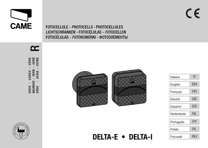
CAME R Series User manual

CAME

CAME R Series User manual

CAME DXR20CAP User manual

CAME

CAME DXR20CAP User manual

CAME DXR20SAP User manual

CAME

CAME DXR20SAP User manual

CAME 001SDTEWL User manual

CAME

CAME 001SDTEWL User manual

CAME DBC 01 User manual

CAME

CAME DBC 01 User manual

CAME PXWDTVE User manual

CAME

CAME PXWDTVE User manual

CAME SMA User manual

CAME

CAME SMA User manual

CAME SIR310 User manual

CAME

CAME SIR310 User manual

CAME MR8570 User manual

CAME

CAME MR8570 User manual

CAME MR8534 User manual

CAME

CAME MR8534 User manual

CAME PXWIRCE User manual

CAME

CAME PXWIRCE User manual

CAME R Series User manual

CAME

CAME R Series User manual

CAME 806TF-0030 User manual

CAME

CAME 806TF-0030 User manual

CAME SMA User manual

CAME

CAME SMA User manual

Popular Security Sensor manuals by other brands

Banner Q5X quick start guide

Banner

Banner Q5X quick start guide

KNX GIRA operating instructions

KNX

KNX GIRA operating instructions

LaserLiner StarSensor 50 operating instructions

LaserLiner

LaserLiner StarSensor 50 operating instructions

Sulzer ABS CA 461 installation guide

Sulzer

Sulzer ABS CA 461 installation guide

Honeywell MIDAS-T-HTP quick start guide

Honeywell

Honeywell MIDAS-T-HTP quick start guide

iGuardFire iGuardStove User & Online Features Manual

iGuardFire

iGuardFire iGuardStove User & Online Features Manual

LEGRAND WattStopper LMUC-100-2 quick start guide

LEGRAND

LEGRAND WattStopper LMUC-100-2 quick start guide

ORORO TWIN-CITIES HEATED GLOVES manual

ORORO

ORORO TWIN-CITIES HEATED GLOVES manual

Jung Mini basic operating instructions

Jung

Jung Mini basic operating instructions

Kopp INFRAcontrol operating instructions

Kopp

Kopp INFRAcontrol operating instructions

Bosch Classic TriTech CM Series installation instructions

Bosch

Bosch Classic TriTech CM Series installation instructions

ZiLOG ZMOTION quick start guide

ZiLOG

ZiLOG ZMOTION quick start guide

Eldes EWP-EXT instruction manual

Eldes

Eldes EWP-EXT instruction manual

Raypak Latching Lockout Module C-5 product manual

Raypak

Raypak Latching Lockout Module C-5 product manual

Honeywell FG-730 installation instructions

Honeywell

Honeywell FG-730 installation instructions

Petzl NEWTON C73000 manual

Petzl

Petzl NEWTON C73000 manual

Lexing LX-MV-400 instructions

Lexing

Lexing LX-MV-400 instructions

Tiras MLT110 manual

Tiras

Tiras MLT110 manual

manuals.online logo
manuals.online logoBrands
  • About & Mission
  • Contact us
  • Privacy Policy
  • Terms and Conditions

Copyright 2025 Manuals.Online. All Rights Reserved.