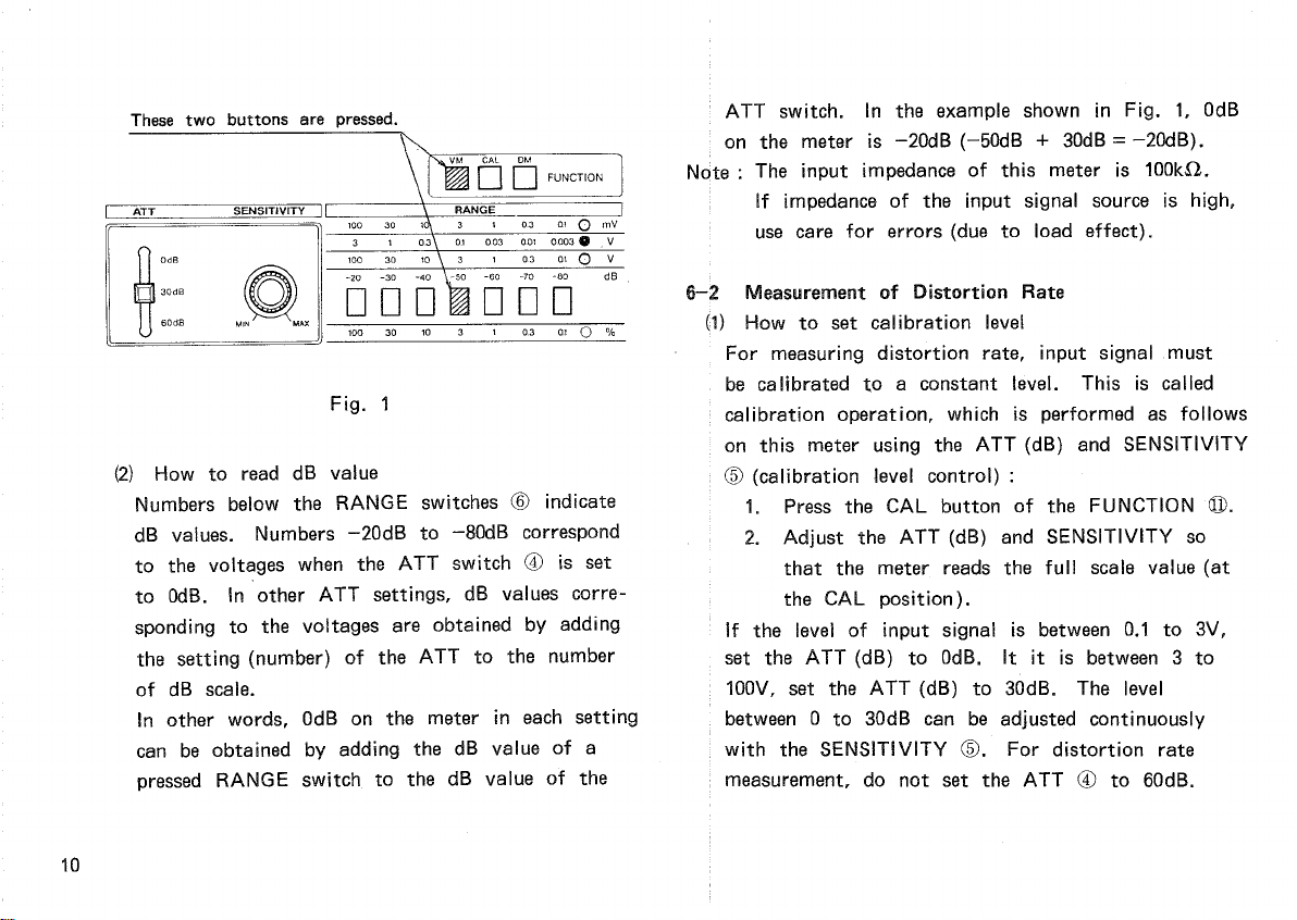
Kenwood HM-250 User manual

©PRINTEDIN*N
KENWOOD
DISTORTION
METER
HM-250
INSTRUCTION
MANUAL
KENWOODCORPORATION

CONTENTS
1.
GENERAL. 3
2.FEATURES3
3.SPECIFICATIONS4
4.PANELEXPLANATION6
5.PRECAUTIONFORUSE8
6.OPERATINGPROCEDURE
...........................
8
A
product
of
KENWOODCORPORATION
17-5,
2-chome,
Shibuya,
Shibuya-ku,
Tokyo
1
50,
Japan
2

1.
GENERAL
2.
FEATURES
The
modelHM-250isa precision
distortion
meter.
Itfeaturescontinuousmeasurement
from
20Hzto20kHz,
0.1%
full
scale
and0.01%(typ.)ofresidual
distortion
rate.
Pushbuttonswitchesonthepanelofferone-touch
operationandsimplifiedcalibrationregardlessof
measurementranges.Automatic
tuning
isadoptedin
thebasicwavereductioncircuittoeliminatecompli-
catedadjustments,enablingeasy-to-useautomatic
operation.
The
HM-250canalsobeusedasa 10Hz-to-200kHz,
100V
full
scale
highly-sensitiveACvoltmeter.
a.
Automatic
tuning
offers
easy
operation.
b.Highsensitivity: 0.1%
full
scale
(distortion
meter)
100V
full
scale
(voltmeter)
c.
One-touchcalibration
d.
Has"X"and"Y"
axis
outputs
forwaveform
observation.
e.
small-sized,
lightweight
and
easy
toinstalland
move.
3

3.
SPECIFICATIONS
[Distortion
Rate
Measurement]
Range
ofmeasurement:
0.1to100%/ F.S.in7 ranges,
in1-3steps(distortionrate^ 30%)
Inputlevelrange: 100mVto100V(with100%
calibration)
^
30mVormore(automatic
tuning
possible)
Basic
wavefreq.range:
20Hz
to20kHzin3 ranges,
with
a
finecontrol
Residual
distortion
rate: 0.01%(Typical)
(at
1kHz,
SENSITIVITY
Control: max)
Higherharmonics: Within±1dBat20Hzto10kHz
(2ndto5th)basicfrequency
Within±2dBat10Hzto20kHz
basic
frequency
*(Higherharmonics^ 60kHz,
distortion
rate^ 30%)
Basic
waverejectionratio:
80dB
ormore
[AC
VoltageMeasurement]
Range
ofmeasurement:
100i"V
to
100V/F.S.
in
1-3steps
Indicationaccuracy:
within
± 3%of
full
scale
(at1kHz)
Residual
noise: 5%or
less
ofmeter
full
scale
(in0.1mVrange
with
closed
input)
Frequency
response: ± 0.5dB
from
20Hzto20kHz
±1dB
from
10Hzto200kHz
(withrespectto1kHz)
[CommonSpecification]
Meterindicationsystem:
Average
valuedetection,
effectivevalueindication
(Calibrationbasedon
input
sine
wave)
X-outcharacteristics: Outputsbasicwavecomponents
inDMmode.
Outputvoltage: Approx.1Vrms
(when
tuned
with
100%calibra-
tion)
4

Output
impedance: Approx.2.2kO,
unbalance
Y-outcharacteristics: OutputshigherharmonicsinDM
mode.
Outputs
input
signalsinVM
andCALmodes.
Output
voltage: Approx.0.5Vrms
(inmeterF.S.mode)
Output
impedance: Approx.2.2kO,
unbalance
Input
impedance: Approx.100kO,lOOpFor
less
Max.
input
voltage: AtOdBattenuation
120Vrms
or
less
(^60Hz)
200VDC
or
less
(AC
peakvalue+ DC)^ 200V
At30or60dBattenuation
140Vrms
or
less
200VDC
or
less
(AC
peakvalue+ DC)^ 200V
[Environmental]
Operatingtemperatureand
humidity
:
0to40°C,10to90%RH
(Nodewconcentration)
Storagetemperatureand
humidity
:
-10
to50°C,10to80%RH
(Nodewconcentration)
[PowerRequirements]
Voltage& frequency: 100/120/220/240VAC±10%
(max.
250V),
50/60Hz
Power
consumption: Approx.5W
[Dimensions]
212Wx 133Hx 272Dmm
Max.dimensions: 212Wx 156Hx 288Dmm
[Weight]
Approx.3.7kg
[Accessories]
Signalcable(withbanana-
alligatorclips,1 meter): 1
Instructionmanual: 1
Power
cable: 1
5

4.PANELEXPLANATION
6

®
Power
Switch•
(
jb-ON/JB.OFF)
A
push-buttontypeswitchthatturnsthepower
source
onandoff.
Pressing
theswitchturnsthe
poweron.
Pressing
itagainturnsthepoweroff.
(D
Meter
Indicates
measured
values.
©
INPUT
Terminal
Inputsignalstobemeasured
into
thisthrminal.
®
ATT(dB)Switch
Attenuates
input
signals.
Three
attenuation
levels
are
available: 0,30and
60dB.
©
SENSITIVITY
control
Controls
thecalibration
level.
©
RANGE
selectorswitch
Selects
themeterrange.7 rangesareavailable
in1-3
steps.
©
Measurementrangeindicatorlamps
Indicate
themodeselected
with
the
FUNCTION
switch
© andthemeterrangeselected
with
the
ATT
switch®.
®
X-OUTPUT
terminal
This
terminaloutputs
basic
waveintheDMmode.
Used
together
with
the
Y-OUTPUT
terminalfor
easy
frequencyadjustmentbydisplaying
Lissajous
waveforms
onanoscilloscope.
®
I
GND
terminalofthismeter.
©
Y-OUTPUT
terminal
This
terminaloutputshigherharmonicsinthe
DMmode,oritoutputsthe
input
signalinthe
VM
orCALmode.IntheDMmode,theterminal
is
usedthe
same
wayasthe
X-OUTPUT
terminal.
©
FUNCTION
selectorswitch
Selects
anyofthe
following
threemeasurement
modes
:
VM
: ACvoltmetermode
CAL
: Calibrationmode
DM: Distortionmetermode
©
MULTI
Switch
Selects
10,100,or1kHzrange.
Set
the
FREQUENCY
dialtox10,xl00orxtGOO
positionfor
each
range.
©
FINE
adjustment
A
knobforfrequencyfineadjustment.
@
FREQUENCY
(Hz)adjustment
A
dialforfrequencyroughadjustment.
7

5.
PRECAUTION
FORUSE
a.
Donotapply
excessively
highvoltagetotheinput
terminal.
b.Donotapplyvoltagetothe
output
terminal.
c.
Donot
press
anypushbuttontwiceormore.
d.
Thesupplyvoltageshouldbewithintherating
voltage±10%(Max.
250V).
e.
Usethemeteratanambienttemperaturefrom
15
to35°C.Donotplacethemeterclosetoa
heat
generatingobject.
f.Donotapply
excessive
forcetothemeter,dial,
inputterminal,etc.
g.
Wipe
dirt
offthepanel,etc.withsoftcloth.
Use
weakneutraldetergentfor
dirt
ifitcannot
bewipedoffwithclothonly.
h.Ifpowersupplycontainspulsenoise,a higher
value
maybeindicatedormonitorwaveformmay
beinfluenced.
6.
OPERATING
PROCEDURE
©PowerON
connecttheattachedpowercabletothemeter
and
a wallsocket.
Press
the
POWER
switch®
and
powerissuppliedtothemeter.
®Priortoapplyinginputsignal
Excessive
inputsignalmaydamagethismeter.
Before
applyinginput
signal,
settheswitchesas
follows:.
ATT
switch® : 60(dB)
RANGE
switch® :
Press
theleftbutton.
IntheVMmode,the
full
scale
ofthismeteris
100V
undertheabovesetting.
Note: Thefollowingtableshowstherelationship
betweenthemaximuminputvoltagesand
settingsoftheATTswitch®.Ifapplied
voltageishigherthanspecifiedinthe
followingtable,themeterisdamaged.
Never
applya voltagehigherthanspecified.
8

6-1ACVoltageMeasurement
DependingonthesettingsoftheATTand
RANGE
switches,
thismetermeasures
input
voltage
from
0.1mVto100V.IftheATTswitchissettoOdB,
theupper
scale
ofthe
RANGE
switch0.1mVto
lOOmVisselected.IftheATTswitchissetto
30dB,
themid
scale
0.003V.to3Visselected.
IftheATTswitchissetto60dB,thelower
scale
0.1Vto100Visselected.Ifthelevelof
input
signalisunknown,selectthelowestsensitivity
rangeasdescribedinthepreviousparagraph.
The
impedanceofthe
input
terminalis
tOOkO.
The
maximum
input
voltageisasshowninTable1.
AdjusttheATTand
RANGE
switchesso
that
the
meterreadsa value
from
1/3ofthe
full
scale
andthe
full
scale.
(1)
Howtoreadvoltage
Three
meterrangesareavailableforACvoltage
measurement.The
right
lampindicatesa selected
range.Thenumbersabovethepressed
RANGE
switchintherowindicatedbythelampshow
theselectedrange.
IntheexampleshowninFig.1,the0.1Vrange
is
selected.Division10onthemetercorresponds
to0.1V.TheATTswitchandthemeasurement
rangeindicatorlampcorrespondtoeachotherin
theverticaldirection.
Note
: Ifthelevelof
input
signalisunknown,be
sure
tosettheATTandmeterrangetothe
minimumsensitivity,thenapply
input
signal.
9
'* (ACpeakvalue+ DC)^ 200V
Table
1 Maximum
Input
Voltage
ATT
Setting Max.
Input
Voltage*
0(dB)
120
VACrmsor
less,
200VDCor
less
30
(dB)
140
VACrmsor.
less,
200VDCor
less
60
(dB)
140
VACrmsor
less,
200VDCor
less

These
twobuttonsare
pressed.
(2)
HowtoreaddBvalue
Numbersbelowthe
RANGE
switches© indicate
dB
values.
Numbers-20dBto-80dBcorrespond
tothevoltageswhentheATTswitch© isset
toOdB.InotherATTsettings,dBvaluescorre-
spondingtothevoltagesareobtainedbyadding
thesetting(number)oftheATTtothenumber
ofdB
scale.
Inotherwords,OdBonthemeterineachsetting
can
beobtainedbyaddingthedBvalueofa
pressed
RANGE
switchtothedBvalueofthe
I
ATTswitch.IntheexampleshowninFig.1,OdB
j
onthemeteris-20dB(-50dB+ 30dB=
-20dB).
Nc|te: The
input
impedanceofthismeteris100kO.
Ifimpedanceofthe
input
signalsourceishigh,
I
usecareforerrors(duetoloadeffect).
6—MeasurementofDistortionRate
^1)
Howtosetcalibrationlevel
For
measuring
distortion
rate,
input
signalmust
becalibratedtoa constantlevel.
This
iscalled
calibrationoperation,whichisperformedasfollows
onthismeterusingtheATT(dB)and
SENSITIVITY
©(calibrationlevelcontrol):
1.
Press
theCAL
button
ofthe
FUNCTION
©.
2.
AdjusttheATT(dB)and
SENSITIVITY
so
thatthemeterreadsthe
full
scale
value(at
theCALposition).
Ifthelevelof
input
signalisbetween0.1to3V,
set
theATT(dB)toOdB.Ititisbetween3 to
100V,
settheATT(dB)to30dB.Thelevel
between0 to30dBcanbeadjustedcontinuously
with
the
SENSITIVITY
©.For
distortion
rate
measurement,
donotsettheATT© to60dB.
10
Fig.
1

(2)
Tuning
Distortion
ratemeasurementrequires
tuning
of
thenotch
filter
forremovingthe
basic
waves.
This
meterprovidesautomatictuning.However,
rough
adjustmentshallbecarriedoutmanually.
1.
Press
theleftmost
button
(100%)
ofthe
RANGE
®.
2.
Press
theDM
(distortion
ratemeasurement)
button
ofthe
FUNCTION
©.
3.
SettheMULTI(frequencyrangeselector)
switch
@ inaccordance
with
the
basic
frequency.
Thefrequencyrangesareas
follows:
10
: 20Hzto200Hz
100
: 200Hzto2kHz
1k
: 2kHzto20kHz
4.
Adjustthe
FREQUENCY
dial@ (frequency
rough
adjustment)and
FINE
knob@
(frequency
fineadjustment)todecreasethe
value
indicatedonthemeter.Whenthe
value
indicatedonthemeterlowersbelow
15%,
increasethemeterrangesensitivityto
read
indication.Thenumbersinthelowest
row(withlampON)indicatetherangefor
distortion
ratemeasurement.
Frequency
adjustmentisfacilitatedbycon-
nectingtheX ® andY ©
OUTPUT
termi-
nals
ofthismetertoanoscilloscopeas
shown
inFig.2 andobserving
Lissajous
waveforms
ontheoscilloscope.
Note
that
automatic
tuning
isdeactivated
ifthemeterrangeissetto100or30%.
The
scale
onthe
FREQUENCY
dialisfor
rough
adjustmentandisnotaccurate.
The
FINE
knodenablesfineadjustmentof
±10%
for20divisionsonthe
FREQUENCY
dialand± 1%for2 divisions.Setthe
FINE
knobtothecenterusually.
11

HM-250
Oscilloscope
Waveformonoscilloscope(in100%range)
Incompletetuning Completetuning
Fig.
2
Lissajous
Waveform
Monitoring
(3)
Measurementofsignallevelto
distortion
rate
characteristics
Tuningisneedlessforsignalsatthesamefre-
quency
with
differentlevel.Measurementcanbe
performedina shorttimeasfollows:
1.
Press
theCAL
button
ofthe
FUNCTION
©.
2.
Adjustthemetertoits
full
scale
with
the
ATT
(dB)® and
SENSITIVITY
®.
3.
Press
theDM
button
ofthe
FUNCTION.
4.
Setthemeterrangeagain,if
necessary,
and
read
indication.
5.
Repeatoperations1 to4 above.
Ifthefrequencyhasbeenchanged,
tuning
is
required.Followtheinstructionsbelow:
1.
Press
theCAL
button
ofthe
FUNCTION.
2.
Adjustthemetertoits
full
scale
with
the
ATT
(dB)and
SENSITIVITY.
3.
Setthemeterrangeto100%.
4.
Press
theDM
button
ofthe
FUNCTION.
5.
Setthemeterindicationtoa valuebelow
15%
with
the
MULTI,
FREQUENCY
and
FINE.
6.
Boostthesensitivityofthemeterandread
itsindication.
7.
Repeatoperations1 to6 above.
(4)
Analyzinghigherharmonicsusing
Lissajous
waveform
Observing
Lissajous
curveformedbythecomparison
of
distortion
(higherharmonics)andthebasicwaves
enables
simpleanalysisofhigherharmonics.
Fig.
3 showsanexample.
12
Signal
generator
Test
piece
(Amplifier,etc.)

(a)Much2ndharmonicsarecontained
(b)Much3rdharmonicsarecontained
(c)
Muchhigherharmonicsarecontained
Fig.
3 HigherHarmonicsAnalysisusing
Lissajous
Waveform
6-3Usageas
Band-Pass
Filter
The
X
OUTPUT
terminaloutputssignals
through
a
band-pass
filter.
Usageofthisterminalisthe
same
asdescribedinparagraph6-2Distortion
Rate
Measurementabove.TheX
OUTPUT
termi-
nal
isinvalidforACvoltagemeasurement.The
meterrangeshallbesetto100%or30%.
To
setthecenterfrequencyoftheband-pass
filter,
maximizethelevelofintendedsignalwhile
observingthelevelofthesignals
output
from
theX terminal.Atthistime,adjustthesignal
level
properly
through
calibrationdescribedin
6-2—(1)
toavoidsaturationoftheinternal
circuit.
The
selectivityoftheband-pass
filter
Q isapprox.
approx.5.
Q=(centerfrequency)/(band
width
at-3dBpoint)
6-4Outputs
Details
oftheX andY outputsofthismeter
are
asfollows:
X
output
: Outputsthebasicwave(for
distortion
ratemeasurement)
Approx.IVrmswhentunedto100%
calibration.
Y
output
: Outputshigherharmonics(for
distortion
ratemeasurement)or
input
signal
(forACvoltagemeasurement).
Approx.0.5Vrmsatthe
full
scale
ofthemeter.
The
impedanceofthe
both
outputsisapprox.2.2kl2.
.UsingtheY
OUTPUT
terminalenablestheuserto
use
thismeterasa lownoiseamplifier.Itsgain
varies
dependingonthemeterrangesettings.
13

Itis74dB(5000times)inthe
O.fmV
range,or
-46dB(0.005
time)
inthe100Vrange.
Note
that
theY
output
signalsa certaincrossover
distortion.
Note
: Ifsignalsare
applied
totheX orY
OUTPUT
terminal,the
meter
isdamaged.Never
apply
signalstotheseterminals.
14
Table of contents
Other Kenwood Measuring Instrument manuals

Kenwood
Kenwood VT-183 User manual

Kenwood
Kenwood VT-173 User manual

Kenwood
Kenwood VT-175 User manual

Kenwood
Kenwood VT-176 User manual

Kenwood
Kenwood VT-181 User manual

Kenwood
Kenwood FL-140 User manual

Kenwood
Kenwood FL-180A User manual

Kenwood
Kenwood VT-172 User manual

Kenwood
Kenwood MS-1660 User manual

Kenwood
Kenwood DM-81 User manual