Elsner KNX L User manual

Brightness Sensor KNX L
Technical specifications and installation instructions
EN
Elsner Elektronik GmbH Control and Automation Engineering
Herdweg 7
Germany Fax +49 (0) 70 56 / 93 97-20 www.elsner-elektronik.de

2 Description
KNX L brightness sensor • Date of issue: 05.11.2010 • Technical changes reserved. Errors reserved.
1. Description
The KNX L brightness sensor measures the intensity of illumination and transfers
the value to the KNX system. Six switching outputs with adjustable threshold values
as well as additional AND and OR logic gates are available. The sensor system, the eva-
luation electronics and the electronics of the bus connection are mounted in a compact
housing.
Functions:
•Brightness measurement: The current light intensity is measured by a
sensor
•3 switching outputs for twilight (up to 1000 lux), 3 for daylight (1-99 klux),
each with adjustable threshold values (Threshold values can be set by
parameter or via communication objects)
•8 AND and 8 OR logic gates with each 4 inputs. Every switching incident as
well as 8 logic inputs (in the form of communication objects) may be used as
inputs for the logic gates. The output of each gate may optionally be configured
as 1 bit or 2 x 8 bits
Configuration is made using the KNX software ETS. The programme file (format
VD2), the data sheet and the manual can be downloaded from the Elsner Elektronik
homepage on www.elsner-elektronik.de in the “Service” menu.
1.1. Technical specifications
Housing Plastic material
Colour White / translucent
Mounting On-wall
Protection category IP 44
Dimensions approx. 96 × 77 × 118 (W × H × D, mm)
Weight approx. 150 g
Ambient temperature Operation -30…+50°C, storage -30…+70°C
Operating voltage KNX bus voltage
Current max. 10 mA, residual ripple 10%
Data output KNX +/- bus terminal plug
BCU type Own micro controller
PEI type 0
Group addresses max. 254
Allocations max. 255
Communication objects 117
Measurement range
brightness
0...150.000 lux
3 Installation and commissioning
KNX L brightness sensor • Date of issue: 05.11.2010 • Technical changes reserved. Errors reserved.
The following standards have been considered for the evaluation of the product in
terms of electro magnetic compatibility:
Transient emissions:
• EN 60730-1:2000 Section EMV (23, 26, H23, H26) (threshold category: B)
• EN 50090-2-2:1996-11 + A1:2002-01 (threshold category: B)
• EN 61000-6-3:2001 (threshold category: B)
Interference resistance:
• EN 60730-1:2000 Section EMV (23, 26, H23, H26)
• EN 50090-2-2:1996-11 + A1:2002-01
• EN 61000-6-1:2004
The product has been tested for the above mentioned standards by an accredited EMV
laboratory.
2. Installation and commissioning
2.1. Notes on installation
Installation, inspection, commissioning and troubleshooting of
the device must only be carried out by a competent electrician.
Disconnect all lines to be assembled, and take safety precautions against accidental
switch-on.
The device is exclusively intended for appropriate use. With each inappropriate change
or non-observance of the instructions for use, any warranty or guarantee claim will be
void.
After unpacking the device, check immediately for any mechanical damages. In case of
transport damage, this must immediately notified to the supplier.
If damaged, the device must not be put into operation.
If an operation without risk may supposedly not be guaranteed, the device must be put
out of operation and be secured against accidental operation.
The device must only be operated as stationary system, i.e. only in a fitted state and
after completion of all installation and start-up works, and only in the environment in-
tended for this purpose.
Resolution (brightness) 1 lux at 0…120 lux
2 lux at 121…1.046 lux
63 lux at 1.047…52.363 lux
423 lux at 52.364…150.000 lux
Accuracy (brightness) ±35%
4 Installation and commissioning
KNX L brightness sensor • Date of issue: 05.11.2010 • Technical changes reserved. Errors reserved.
Elsner Elektronik does not assume any liability for changes in standards after publica-
tion of this instruction manual.
2.2. Location
Select an assembly location at the building where sun may be collected by the sensors
unobstructedly. The sensor may not be shaded by the building or for example by trees.
2.3. Mounting the sensor
2.3.1. Attaching the mount
The sensor comes with a combination wall/pole mount. The mount comes adhered by
adhesive strips to the rear side of the housing.
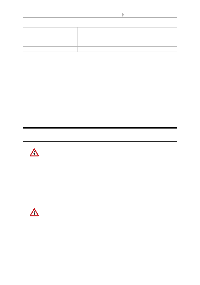
Fig. 1
Align the device in a southward direction.
North
South
Fig. 2
The sensor must be mounted onto a vertical
wall (or pole).
Wall
or
pole
Fig. 3
The sensor must be mounted horizontally in
the lateral direction.
horizontal
5 Installation and commissioning
KNX L brightness sensor • Date of issue: 05.11.2010 • Technical changes reserved. Errors reserved.
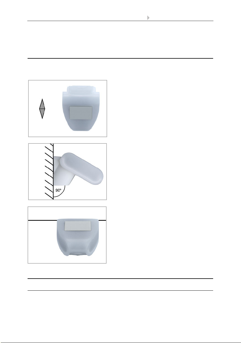
Fasten the mount vertically onto the wall or pole.
Fig. 1
When wall mounting: flat side on wall, crescent-
shaped collar upward.
Collar
Fig. 2
When pole mounting: curved side on pole, collar
downward.
Collar
Fig. 3
An additional, optional accessory available from
Elsner Elektronik is an articulated arm for flexib-
le wall, pole or beam mounting of the sensor.
Fig. 4
Example uses of the hinge arm mounting: With
the hinge arm mounting, the sensor peeps out
from beneath the roof overhang.
6 Installation and commissioning
KNX L brightness sensor • Date of issue: 05.11.2010 • Technical changes reserved. Errors reserved.
2.3.2. View of rear side and drill hole plan
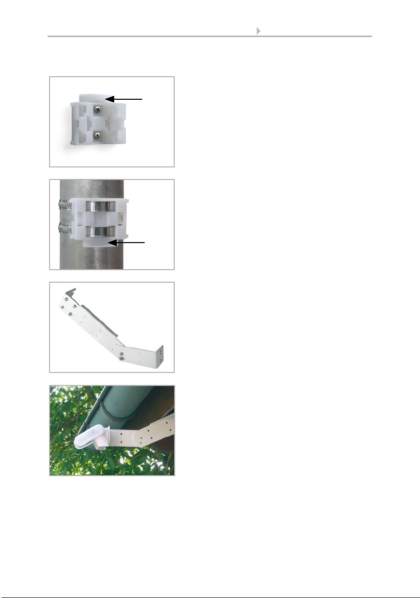
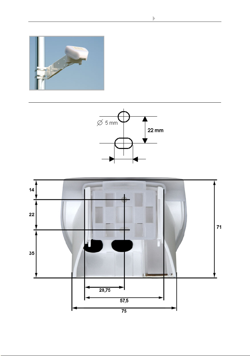
Fig. 5
Example uses of the hinge arm mounting: Fit-
ting to a pole with worm drive hose clips
Langloch 7,5 x 5 mm
Fig. 6 a+b
Drill hole plan
Dimensions of rear side of
housing with bracket. Sub-
ject to change for technical
enhancement.
7 Installation and commissioning
KNX L brightness sensor • Date of issue: 05.11.2010 • Technical changes reserved. Errors reserved.
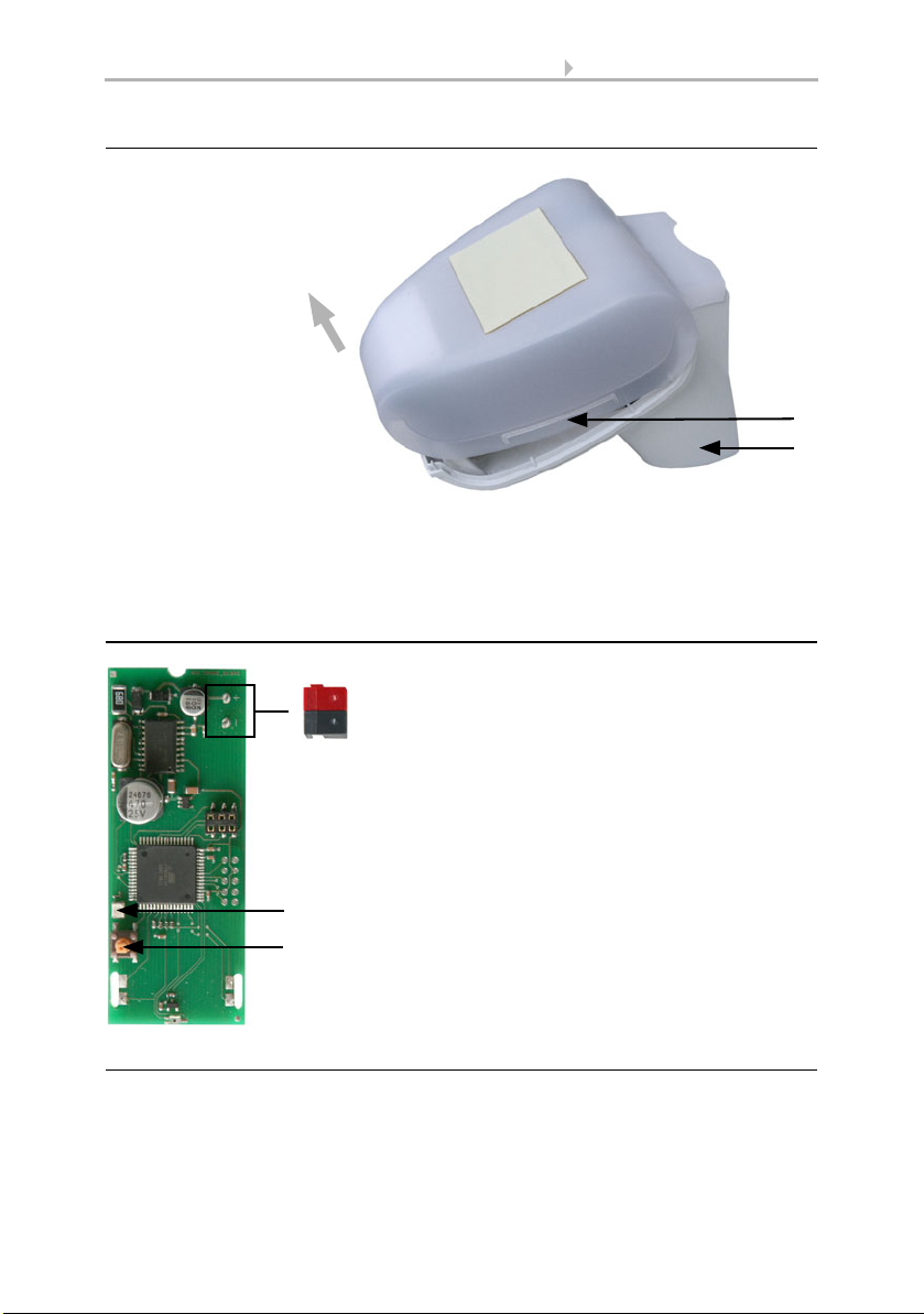
2.3.3. Preparing the sensor
The sensor cover snaps in on the left and right along the bottom edge (see Fig.). Re-
move the cover.
Push the bus connection cable through the rubber seal on the bottom of the sensor and
connect bus +/- to the provided clamps.
2.3.4. PCB layout
2.3.5. Mounting the sensor
Close the housing by putting the cover back over the bottom part. The cover must snap
in on the left and right with a definite “click”.
Fig. 7
1 Cover Snaps
2 Bottom part of housing
1
2
Unsnap cover and
remove upwards
Fig. 8
1SlotforKNXclamp+/-
2 Programming LED
3 Programming pushbutton for
the teach-in of the device
3
2
1

8 Maintenance
KNX L brightness sensor • Date of issue: 05.11.2010 • Technical changes reserved. Errors reserved.
To remove it, the sensor can be simply pulled upwards out of the mount, against the
resistance of the fastening.
2.4. Notes on mounting and commissioning
Do not open the device if water (rain) might ingress: even some drops might damage
the electronic system.
After the bus voltage has been applied, the device will enter an initialisation phase las-
ting 5 seconds. During this phase no information can be received via the bus.
3. Maintenance
The sensor must regularly be checked for dirt twice a year and cleaned if necessary. In
case of severe dirt, the sensor may not work properly anymore.
As a precaution, the device should always be separated from
bus current for maintenance works.
Fig. 9
Make sure the cover and bottom part are pro-
perly snapped together! This picture is loo-
king at the closed sensor from underneath.
Fastening
Fig. 10
Push the housing from above into the faste-
ned mount. The bumps on the mount must
snap into the rails in the housing.
Table of contents
Other Elsner Accessories manuals

Elsner
Elsner Cala KNX AQS/TH Guide

Elsner
Elsner KNX T-UP gl Guide

Elsner
Elsner Vari KNX 3L-TH-D Guide

Elsner
Elsner KNX RW Guide

Elsner
Elsner KNX AQS/TH-B-UP Series Guide

Elsner
Elsner Sewi KNX TH-L-Pr Guide

Elsner
Elsner KNX R Guide

Elsner
Elsner Leak User manual

Elsner
Elsner 71300 Guide

Elsner
Elsner KNX AQS/TH Guide


