Elsner KNX VOC-UP basic Guide
KNX VOC-UP basic
Mixed Gas Sensor
Item number 70244 (white)
EN
Installation and Adjustment


1 Contents
Elsner Elektronik GmbH • Sohlengrund 16 • 75395 Ostelsheim • Germany
Mixed gas sensor KNX VOC-UP basic • from software version 0.3.6, ETS programme version 1.1 • Version: 27.01.2020 •
Technical changes reserved. Errors reserved.
1. Description ........................................................................................... 3
1.0.1. Scope of delivery .......................................................................................... 3
1.1. Technical specifications ........................................................................................... 4
1.1.1. Accuracy of the measurement ..................................................................... 4
1.1.2. Measuring ranges of different gases (CO2 equivalents) ........................... 4
2. Installation and commissioning ........................................................... 5
2.1. Installation notes ...................................................................................................... 5
2.2. Installation position .................................................................................................. 6
2.3. Composition ............................................................................................................. 6
2.3.1. Housing .......................................................................................................... 6
2.3.2. Rear view of sensor board with connections ............................................. 7
2.4. Assembly of the sensor ........................................................................................... 7
2.5. Notes on mounting and commissioning ................................................................ 7
3. Addressing of the device at the bus .................................................... 7
4. Transfer protocol ................................................................................. 8
4.1. List of all communications objects ......................................................................... 8
5. Parameter setting .............................................................................. 13
5.1. Behaviour on power failure/ restoration of power .............................................. 13
5.2. General settings ..................................................................................................... 13
5.3. VOC measured value ............................................................................................. 14
5.4. VOC threshold values ............................................................................................ 14
5.4.1. VOC threshold value 1, 2, 3, 4 .................................................................... 14
5.5. VOC PI control ........................................................................................................ 17
5.6. Variable comparator .............................................................................................. 19
5.6.1. Control variable comparator 1/2 ................................................................ 19
5.7. Logic ........................................................................................................................ 20
5.7.1. AND and/or OR logic 1/2/3/4/5/6/7/8 .......................................................... 21
5.7.2. AND logic connection inputs ..................................................................... 22
5.7.3. Connection inputs of the OR logic ............................................................. 23

2 Clarification of signs
This manual is amended periodically and will be brought into line with new software
releases. The change status (software version and date) can be found in the contents footer.
If you have a device with a later software version, please check
www.elsner-elektronik.de in the menu area "Service" to find out whether a more up-to-
date version of the manual is available.
Clarification of signs used in this manual
Installation, inspection, commissioning and troubleshooting of the device
must only be carried out by a competent electrician.
Safety advice.
Safety advice for working on electrical connections, components,
etc.
DANGER! ... indicates an immediately hazardous situation which will lead to
death or severe injuries if it is not avoided.
WARNING! ... indicates a potentially hazardous situation which may lead to
death or severe injuries if it is not avoided.
CAUTION! ... indicates a potentially hazardous situation which may lead to
trivial or minor injuries if it is not avoided.
ATTENTION! ... indicates a situation which may lead to damage to property if it is
not avoided.
ETS In the ETS tables, the parameter default settings are marked by
underlining.

3 Description
Mixed Gas Sensor KNX VOC-UP basic • Version: 27.01.2020 • Technical changes reserved. Errors reserved.
1. Description
The Mixed Gas Sensor KNX VOC-UP basic recognizes volatile organic compounds
in the room air. The indoor sensor can receive an external VOC value via the bus and
process it with the own data to an overall value (mixed value, e. g. room average).
The KNX VOC-UP basic provides four switching outputs with adjustable threshold
values. The switching outputs and further communication objects can be linked by
AND and OR logic gates. Additionally, an integrated actuating variable comparator can
compare and output values that are received via communication objects.
An integrated PI controllers allows for control of ventilation depending on VOC
concentration.
The housing is completed with a frame of the switching series installed in the building
and thus merges with the interior.
Functions:
• Measurement of VOC (volatile organic compounds) in the air. In this process,
an air quality value in CO2equivalents is calculated via an algorithm from the
sum signal of all compounds included in the mixed gas.
•Mixed value from own measured value and external value (proportions can
be set in percentage)
•PI controller for ventilation depending on VOC concentration:
dehumidification/humidification (one step) or dehumidification (one or two
step)
•4 switching outputs with adjustable threshold values (Threshold values can
be set by parameter or via communication objects)
•8 AND and 8 OR logic gates with each 4 inputs. Every switching incident as
well as 8 logic inputs in the form of communication objects may be used as
inputs for the logic gates. The output of each gate may optionally be configured
as 1 bit or 2 x 8 bits
•2 actuating variable comparators for output of minimum, maximum or
average values. Each with 5 inputs (for values received via communication
objects)
Configuration is made using the KNX software ETS. The product file can be
downloaded from the Elsner Elektronik website on www.elsner-elektronik.de in the
“Service” menu.
1.0.1. Scope of delivery
• Housing with display, buttons and sensor board
• Base plate
You will need in addition (not supplied):
• Socket Ø 60 mm, 42 mm deep
• Frame (for element 55 x 55 mm), suitable for the switching programme used in
the building

4 Description
Mixed Gas Sensor KNX VOC-UP basic • Version: 27.01.2020 • Technical changes reserved. Errors reserved.
1.1. Technical specifications
The product conforms with the provisions of EU directives.
1.1.1. Accuracy of the measurement
Measurement variations from sources of interference (see chapter Installation
position) must be corrected in the ETS in order to ensure the specified accuracy of the
sensor (offset). To ensure a correct VOC measurement, the device must be installed in
a windproof socket.
The indicated accuracy of the VOC measurement will be achieved after a room air
exchange (without interruption of the bus voltage) if the sensor has been in contact
with fresh air at least once in this period. After this, the sensor will recalibrate itself at
regular intervals.
To guarantee the accuracy on a sustained basis, the sensor should be provided with
fresh air at least once in 48 hours. This occurs normally during room ventilation.
1.1.2. Measuring ranges of different gases (CO2 equivalents)
Corresponding VOC concentrations for specific representatives
Housing Plastic material (partly lacquered)
Colours • White glossy (similar to RAL 9016 Traffic White)
• Special colours on request
Mounting In-wall (in socket Ø60 mm, 42 mm deep)
Protection category IP 20
Dimensions Housing approx. 55 x 55 (W x H, mm),
mounting depth approx. 15 mm,
base plate approx. 71 x 71 (W x H, mm)
Total weight approx. 55 g
Ambient temperature Operation 0…+50°C, storage -20…+50°C
Ambient air humidity avoid bedewing
Operating voltage KNX bus voltage
Bus current max. 10 mA; max. 500 mW
Data output KNX +/- bus terminal plug
BCU type Own micro controller
PEI type 0
Group addresses max. 254
Allocations max. 254
Communication objects 133
Measurement range 450...2000 ppm
Resolution 1 ppm
5 Installation and commissioning
Mixed Gas Sensor KNX VOC-UP basic • Version: 27.01.2020 • Technical changes reserved. Errors reserved.
* corresponding concentration range based on lab measurements at gas mixing system with synthetic air at 50% r.h. and RT
2. Installation and commissioning
2.1. Installation notes
Installation, testing, operational start-up and troubleshooting should
only be performed by an electrician.
CAUTION!
Live voltage!
There are unprotected live components inside the device.
• National legal regulations are to be followed.
• Ensure that all lines to be assembled are free of voltage and take
precautions against accidental switching on.
• Do not use the device if it is damaged.
• Take the device or system out of service and secure it against
unintentional use, if it can be assumed, that risk-free operation is no
longer guaranteed.
The device is only to be used for its intended purpose. Any improper modification or
failure to follow the operating instructions voids any and all warranty and guarantee
claims.
After unpacking the device, check it immediately for possible mechanical damage. If it
has been damaged in transport, inform the supplier immediately.
Compound Formula Range*
(ppm)
Potential sources of pollutants
indoors
Carbon monoxide CO 0-10 Car exhaust, fuel-based heating, cook-
ing appliances, smoking
Methane CH40-200 Natural gas
Propane C3H80-20 Fuel-based heating, cooking appli-
ances, cleaners
Ethyl alcohol C2H6O 0-3 Cosmetics, cleaners, disinfectants,
detergents, paints, coatings, breath
Acetaldehyde C2H4O 0-20 Adhesives, coatings, plastics,
lubricants, ripening of fruits
Methylethylketone C4H8O 0-20 Adhesives, coatings, plastics,
lubricants
Toluene C7H80-5 Paints, coatings, cleaners, detergents,
smoking, polyurethane lacquers

6 Installation and commissioning
Mixed Gas Sensor KNX VOC-UP basic • Version: 27.01.2020 • Technical changes reserved. Errors reserved.
The device may only be used as a fixed-site installation; that means only when
assembled and after conclusion of all installation and operational start-up tasks and
only in the surroundings designated for it.
Elsner Elektronik is not liable for any changes in norms and standards which may occur
after publication of these operating instructions.
2.2. Installation position
The Mixed Gas Sensor KNX VOC-UP basic will be installed concealed within a
socket (Ø 60 mm, 42 mm deep).
May be installed and operated in dry interior rooms only.
Avoid condensation.
For monitoring of the VOC content of the room air choose an installation position in
height of head (standing or sitting, according to utilization of room).
When selecting an installation location, please ensure that the measurement results
are affected as little as possible by external influences. Possible sources of interference
include:
• Drafts from windows and doors
• Draft from ducts which lead from other rooms or from the outside to the
junction box in which the sensor is mounted
Measurement variations from such sources of interference must be corrected in the
ETS in order to ensure the specified accuracy of the sensor (offset).
To ensure a correct VOC measurement, the device must be installed in a windproof
socket.
2.3. Composition
2.3.1. Housing
Fig. 1
1Notches
2 Air circulation holes
3 Programming LED (recessed)
4 Programming button (recessed)
for teaching instrument
5 Air circulation holes (BOTTOM)
2
1
4
3
5
7 Addressing of the device at the bus
Mixed Gas Sensor KNX VOC-UP basic • Version: 27.01.2020 • Technical changes reserved. Errors reserved.
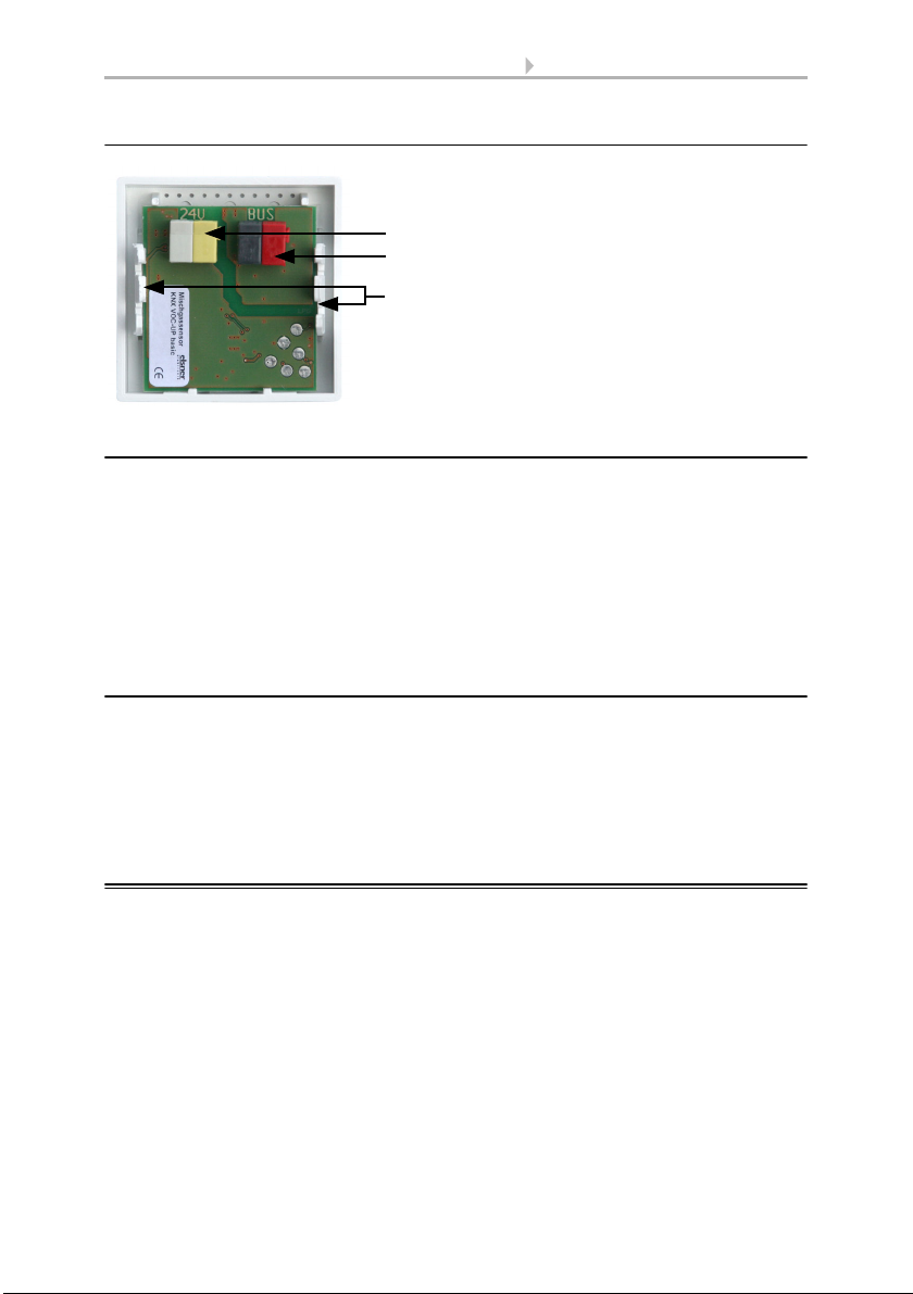
2.3.2. Rear view of sensor board with connections
2.4. Assembly of the sensor
First of all fit the windproof socket with connection. Also seal inlet pipes to avoid
infiltration.
Screw the base plate onto the socket and position the frame of the switching
programme. Connect the auxiliary voltage and the bus line +/- (black-red plug) to the
terminals provided on the board.
Pin the sensor with the notches on to the metal frame, so that sensor and frame are
fixed.
2.5. Notes on mounting and commissioning
Never expose the device to water (e.g. rain) or dust. This can damage the electronics.
You must not exceed a relative humidity of 95%. Avoid condensation.
After the auxiliary voltage has been applied, the device will enter an initialisation phase
lasting a few seconds. During this phase no information can be received or sent via the
bus.
3. Addressing of the device at the bus
The device is supplied with the bus address 15.15.255. You can program another
address into the ETS by overwriting the 15.15.255 address or by teaching via the
programming button.
Fig. 2
1 Terminal auxiliary voltage
12...24 V DC
2 KNX terminal BUS +/-
3Notches
3
1
2

8 Transfer protocol
Mixed gas sensor KNX VOC-UP basic • Version: 27.01.2020 • Technical changes reserved. Errors reserved..
4. Transfer protocol
Units:
VOC content in ppm
Variables in %
4.1. List of all communications objects
Abbreviation flags:
C Communication
R Read
WWrite
T Transfer
UUpdate
No. Text Function Flags DPT type Size
0 Software version readable R-CT 0 2 bytes
2 VOC sensor malfunction Output R-CT [1.1] DPT_Switch 1 bit
96 External VOC reading Input -WC- 0 2 bytes
97 Internal VOC reading Output R-CT 0 2 bytes
98 Total VOC reading Output R-CT 0 2 bytes
99 VOC maximum value request Input -WC- [1.1] DPT_Switch 1 bit
100 Maximum VOC reading Output R-CT 0 2 bytes
101 Reset VOC maximum value Input -WC- [1.1] DPT_Switch 1 bit
102 VOC threshold value 1: Abso-
lute value
Input/Out-
put
RWCT 0 2 bytes
103 VOC threshold value 1: (1:+ | 0:-) Input -WC- [1.1] DPT_Switch 1 bit
104 VOC threshold value 1: Swit-
ching delay from 0 to 1
Input -WC- [9.10] DPT_-
Value_Time1
2 bytes
105 VOC threshold value 1: Swit-
ching delay from 1 to 0
Input -WC- [9.10] DPT_-
Value_Time1
2 bytes
106 VOC threshold value 1: Swit-
ching output
Output R-CT [1.1] DPT_Switch 1 bit
107 VOC threshold value 1: Swit-
ching output block
Input -WC- [1.1] DPT_Switch 1 bit
108 VOC threshold value 2: Abso-
lute value
Input/Out-
put
RWCT 0 2 bytes
109 VOC threshold value 2: (1:+ | 0:-) Input -WC- [1.1] DPT_Switch 1 bit
110 VOC threshold value 2: Swit-
ching delay from 0 to 1
Input -WC- [9.10] DPT_-
Value_Time1
2 bytes

9 Transfer protocol
Mixed gas sensor KNX VOC-UP basic • Version: 27.01.2020 • Technical changes reserved. Errors reserved.
111 VOC threshold value 2: Swit-
ching delay from 1 to 0
Input -WC- [9.10] DPT_-
Value_Time1
2 bytes
112 VOC threshold value 2: Swit-
ching output
Output R-CT [1.1] DPT_Switch 1 bit
113 VOC threshold value 2: Swit-
ching output block
Input -WC- [1.1] DPT_Switch 1 bit
114 VOC threshold value 3: Abso-
lute value
Input/Out-
put
RWCT 0 2 bytes
115 VOC threshold value 3: (1:+ | 0:-) Input -WC- [1.1] DPT_Switch 1 bit
116 VOC threshold value 3: Swit-
ching delay from 0 to 1
Input -WC- [9.10] DPT_-
Value_Time1
2 bytes
117 VOC threshold value 3: Swit-
ching delay from 1 to 0
Input -WC- [9.10] DPT_-
Value_Time1
2 bytes
118 VOC threshold value 3: Swit-
ching output
Output R-CT [1.1] DPT_Switch 1 bit
119 VOC threshold value 3: Swit-
ching output block
Input -WC- [1.1] DPT_Switch 1 bit
120 VOC threshold value 4: Abso-
lute value
Input/Out-
put
RWCT 0 2 bytes
121 VOC threshold value 4: (1:+ | 0:-) Input -WC- [1.1] DPT_Switch 1 bit
122 VOC threshold value 4: Swit-
ching delay from 0 to 1
Input -WC- [9.10] DPT_-
Value_Time1
2 bytes
123 VOC threshold value 4: Swit-
ching delay from 1 to 0
Input -WC- [9.10] DPT_-
Value_Time1
2 bytes
124 VOC threshold value 4: Swit-
ching output
Output R-CT [1.1] DPT_Switch 1 bit
125 VOC threshold value 4: Swit-
ching output block
Input -WC- [1.1] DPT_Switch 1 bit
126 VOC controller: Blocking object Input -WC- [1.1] DPT_Switch 1 bit
127 VOC controller: Target value Input/Out-
put
RWCT 0 2 bytes
128 VOC controller: Target value
(1:+ | 0:-)
Input -WC- [1.1] DPT_Switch 1 bit
129 VOC controller: Control variable
ventilation (Level 1)
Output R-CT [5.1] DPT_Sca-
ling
1 byte
130 VOC controller: Control variable
ventilation (Level 2)
Output R-CT [5.1] DPT_Sca-
ling
1 byte
131 VOC controller: Ventilation sta-
tus (1=ON | 0=OFF)
Output R-CT [1.1] DPT_Switch 1 bit
132 VOC controller: Ventilation sta-
tus 2 (1=ON | 0=OFF)
Output R-CT [1.1] DPT_Switch 1 bit
133 Actuating variable comparator
1: Input 1
Input -WC- [5.1] DPT_Sca-
ling
1 byte
No. Text Function Flags DPT type Size

10 Transfer protocol
Mixed gas sensor KNX VOC-UP basic • Version: 27.01.2020 • Technical changes reserved. Errors reserved..
134 Actuating variable comparator
1: Input 2
Input -WC- [5.1] DPT_Sca-
ling
1 byte
135 Actuating variable comparator
1: Input 3
Input -WC- [5.1] DPT_Sca-
ling
1 byte
136 Actuating variable comparator
1: Input 4
Input -WC- [5.1] DPT_Sca-
ling
1 byte
137 Actuating variable comparator
1: Input 5
Input -WC- [5.1] DPT_Sca-
ling
1 byte
138 Actuating variable comparator
1: Output
Output R-CT [5.1] DPT_Sca-
ling
1 byte
139 Actuating variable comparator
1: Block
Input -WC- [1.1] DPT_Switch 1 bit
140 Actuating variable comparator
2: Input 1
Input -WC- [5.1] DPT_Sca-
ling
1 byte
141 Actuating variable comparator
2: Input 2
Input -WC- [5.1] DPT_Sca-
ling
1 byte
142 Actuating variable comparator
2: Input 3
Input -WC- [5.1] DPT_Sca-
ling
1 byte
143 Actuating variable comparator
2: Input 4
Input -WC- [5.1] DPT_Sca-
ling
1 byte
144 Actuating variable comparator
2: Input 5
Input -WC- [5.1] DPT_Sca-
ling
1 byte
145 Actuating variablecomparator 2:
Output
Output R-CT [5.1] DPT_Sca-
ling
1 byte
146 Actuating variablecomparator 2:
Block
Input -WC- [1.1] DPT_Switch 1 bit
147 AND logic 1: 1-bit switching out-
put
Output R-CT [1.1] DPT_Switch 1 bit
148 AND logic 1: 8-bit output A Output R-CT [5] 5.xxx 1 byte
149 AND logic 1: 8-bit output B Output R-CT [5] 5.xxx 1 byte
150 AND logic 1: Switching output
block
Input -WC- [1.1] DPT_Switch 1 bit
151 AND logic 2: 1-bit switching out-
put
Output R-CT [1.1] DPT_Switch 1 bit
152 AND logic 2: 8-bit output A Output R-CT [5] 5.xxx 1 byte
153 AND logic 2: 8-bit output B Output R-CT [5] 5.xxx 1 byte
154 AND logic 2: Switching output
block
Input -WC- [1.1] DPT_Switch 1 bit
155 AND logic 3: 1-bit switching out-
put
Output R-CT [1.1] DPT_Switch 1 bit
156 AND logic 3: 8-bit output A Output R-CT [5] 5.xxx 1 byte
157 AND logic 3: 8-bit output B Output R-CT [5] 5.xxx 1 byte
No. Text Function Flags DPT type Size

11 Transfer protocol
Mixed gas sensor KNX VOC-UP basic • Version: 27.01.2020 • Technical changes reserved. Errors reserved.
158 AND logic 3: Switching output
block
Input -WC- [1.1] DPT_Switch 1 bit
159 AND logic 4: 1-bit switching out-
put
Output R-CT [1.1] DPT_Switch 1 bit
160 AND logic 4: 8-bit output A Output R-CT [5] 5.xxx 1 byte
161 AND logic 4: 8-bit output B Output R-CT [5] 5.xxx 1 byte
162 AND logic 4: Switching output
block
Input -WC- [1.1] DPT_Switch 1 bit
163 AND logic 5: 1-bit switching out-
put
Output R-CT [1.1] DPT_Switch 1 bit
164 AND logic 5: 8-bit output A Output R-CT [5] 5.xxx 1 byte
165 AND logic 5: 8-bit output B Output R-CT [5] 5.xxx 1 byte
166 AND logic 5: Switching output
block
Input -WC- [1.1] DPT_Switch 1 bit
167 AND logic 6: 1-bit switching out-
put
Output R-CT [1.1] DPT_Switch 1 bit
168 AND logic 6: 8-bit output A Output R-CT [5] 5.xxx 1 byte
169 AND logic 6: 8-bit output B Output R-CT [5] 5.xxx 1 byte
170 AND logic 6: Switching output
block
Input -WC- [1.1] DPT_Switch 1 bit
171 AND logic 7: 1-bit switching out-
put
Output R-CT [1.1] DPT_Switch 1 bit
172 AND logic 7: 8-bit output A Output R-CT [5] 5.xxx 1 byte
173 AND logic 7: 8-bit output B Output R-CT [5] 5.xxx 1 byte
174 AND logic 7: Switching output
block
Input -WC- [1.1] DPT_Switch 1 bit
175 AND logic 8: 1-bit switching out-
put
Output R-CT [1.1] DPT_Switch 1 bit
176 AND logic 8: 8-bit output A Output R-CT [5] 5.xxx 1 byte
177 AND logic 8: 8-bit output B Output R-CT [5] 5.xxx 1 byte
178 AND logic 8: Switching output
block
Input -WC- [1.1] DPT_Switch 1 bit
179 OR logic 1: 1-bit switching out-
put
Output R-CT [1.1] DPT_Switch 1 bit
180 OR logic 1: 8-bit output A Output R-CT [5] 5.xxx 1 byte
181 OR logic 1: 8-bit output B Output R-CT [5] 5.xxx 1 byte
182 OR logic 1: Switching output
block
Input -WC- [1.1] DPT_Switch 1 bit
183 OR logic 2: 1-bit switching out-
put
Output R-CT [1.1] DPT_Switch 1 bit
184 OR logic 2: 8-bit output A Output R-CT [5] 5.xxx 1 byte
185 OR logic 2: 8-bit output B Output R-CT [5] 5.xxx 1 byte
No. Text Function Flags DPT type Size

12 Transfer protocol
Mixed gas sensor KNX VOC-UP basic • Version: 27.01.2020 • Technical changes reserved. Errors reserved..
186 OR logic 2: Switching output
block
Input -WC- [1.1] DPT_Switch 1 bit
187 OR logic 3: 1-bit switching out-
put
Output R-CT [1.1] DPT_Switch 1 bit
188 OR logic 3: 8-bit output A Output R-CT [5] 5.xxx 1 byte
189 OR logic 3: 8-bit output B Output R-CT [5] 5.xxx 1 byte
190 OR logic 3: Switching output
block
Input -WC- [1.1] DPT_Switch 1 bit
191 OR logic 4: 1-bit switching out-
put
Output R-CT [1.1] DPT_Switch 1 bit
192 OR logic 4: 8-bit output A Output R-CT [5] 5.xxx 1 byte
193 OR logic 4: 8-bit output B Output R-CT [5] 5.xxx 1 byte
194 OR logic 4: Switching output
block
Input -WC- [1.1] DPT_Switch 1 bit
195 OR logic 5: 1-bit switching out-
put
Output R-CT [1.1] DPT_Switch 1 bit
196 OR logic 5: 8-bit output A Output R-CT [5] 5.xxx 1 byte
197 OR logic 5: 8-bit output B Output R-CT [5] 5.xxx 1 byte
198 OR logic 5: Switching output
block
Input -WC- [1.1] DPT_Switch 1 bit
199 OR logic 6: 1-bit switching out-
put
Output R-CT [1.1] DPT_Switch 1 bit
200 OR logic 6: 8-bit output A Output R-CT [5] 5.xxx 1 byte
201 OR logic 6: 8-bit output B Output R-CT [5] 5.xxx 1 byte
202 OR logic 6: Switching output
block
Input -WC- [1.1] DPT_Switch 1 bit
203 OR logic 7: 1-bit switching out-
put
Output R-CT [1.1] DPT_Switch 1 bit
204 OR logic 7: 8-bit output A Output R-CT [5] 5.xxx 1 byte
205 OR logic 7: 8-bit output B Output R-CT [5] 5.xxx 1 byte
206 OR logic 7: Switching output
block
Input -WC- [1.1] DPT_Switch 1 bit
207 OR logic 8: 1-bit switching out-
put
Output R-CT [1.1] DPT_Switch 1 bit
208 OR logic 8: 8-bit output A Output R-CT [5] 5.xxx 1 byte
209 OR logic 8: 8-bit output B Output R-CT [5] 5.xxx 1 byte
210 OR logic 8: Switching output
block
Input -WC- [1.1] DPT_Switch 1 bit
211 Logic input 1 Input -WC- [1.1] DPT_Switch 1 bit
212 Logic input 2 Input -WC- [1.1] DPT_Switch 1 bit
213 Logic input 3 Input -WC- [1.1] DPT_Switch 1 bit
214 Logic input 4 Input -WC- [1.1] DPT_Switch 1 bit
No. Text Function Flags DPT type Size

13 Parameter setting
Mixed gas sensor KNX VOC-UP basic • Version: 27.01.2020 • Technical changes reserved. Errors reserved.
5. Parameter setting
5.1. Behaviour on power failure/ restoration of
power
Behaviour following a failure of the bus power supply:
The device sends nothing.
Behaviour on bus restoration of power and following programming or reset:
The device sends all outputs according to their send behaviour set in the parameters
with the delays established in the "General settings" parameter block.
5.2. General settings
Set the basic data transfer characteristics and select whether or not malfunction ob-
jects should be sent.
215 Logic input 5 Input -WC- [1.1] DPT_Switch 1 bit
216 Logic input 6 Input -WC- [1.1] DPT_Switch 1 bit
217 Logic input 7 Input -WC- [1.1] DPT_Switch 1 bit
218 Logic input 8 Input -WC- [1.1] DPT_Switch 1 bit
219 Logic input 9 Input -WC- [1.1] DPT_Switch 1 bit
220 Logic input 10 Input -WC- [1.1] DPT_Switch 1 bit
221 Logic input 11 Input -WC- [1.1] DPT_Switch 1 bit
222 Logic input 12 Input -WC- [1.1] DPT_Switch 1 bit
223 Logic input 13 Input -WC- [1.1] DPT_Switch 1 bit
224 Logic input 14 Input -WC- [1.1] DPT_Switch 1 bit
225 Logic input 15 Input -WC- [1.1] DPT_Switch 1 bit
226 Logic input 16 Input -WC- [1.1] DPT_Switch 1 bit
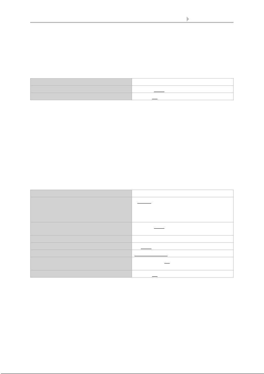
Send delay after power-up and programming for:
Measured values 5 s • ... • 2 h
Threshold values and switching outputs 5 s • ... • 2 h
Controller objects 5 s • 10 s • ... • 2 h
Logic outputs 5 s • 10 s • ... • 2 h
Maximum telegram quota • 1 message per second
• ...
• 5 messages per second
• ...
• 20 messages per second
Use VOC malfunction object Yes • No
No. Text Function Flags DPT type Size

14 Parameter setting
Mixed gas sensor KNX VOC-UP basic • Version: 27.01.2020 • Technical changes reserved. Errors reserved..
5.3. VOC measured value
Use Offsets to adjust the readings to be sent.
The unit can calculate a mixed value from its own reading and an external value. Set
the mixed value calculation if desired.
If an external portion is used, all of the following settings (threshold values, etc.) are
related to the overall reading!
The maximum readings can be saved and sent to the bus . Use the "Reset VOC max.
value" object to reset the value to the current reading.
The values are not retained after a reset.
5.4. VOC threshold values
Activate the threshold values that you want to use here. The Mixed gas sensor KNX
VOC-UP basic provides four threshold values for carbon dioxide.
Table of VOC values:
1000 ppm corresponds to 0.1% VOC content.
5.4.1. VOC threshold value 1, 2, 3, 4
The settings options for temperature, humidity and CO2 threshold values are the same.
Offset in ppm -100...100; 0
Use external reading Yes • No
Ext. Reading proportion of the total reading 5% • 10% • ... • 50% • ... • 100%
Send internal and total reading • never
• periodically
• On change
• on change and periodically
From change of
(if sent on change)
2% • 5% • 10% • 25% • 50% (relative to the
last reading)
Send cycle
(if sent periodically)
5s• ... • 2 h
Use maximum value Yes • No
Use threshold value 1/2/3/4 Yes • No
300 ... 500 ppm Fresh air
1500 ... 3000 ppm "Stale" air
5000 ppm Maximum allowable concentration
15 Parameter setting
Mixed gas sensor KNX VOC-UP basic • Version: 27.01.2020 • Technical changes reserved. Errors reserved.
Threshold value
Set the threshold values directly in the application program using parameters, or de-
fine them via the bus using a communications object.
Threshold value setpoint using parameter:
Set the threshold values and hysteresis directly.
Threshold value setpoint using a communications object:
Beforehand, enter how the threshold value will be received from the bus. Basically, a
new value can be received, or simply a command to increase or decrease.
During initial commissioning, a threshold value must be defined which will be valid un-
til the 1st communication of a new threshold value. For units which have already been
taken into service, the last communicated threshold value can be used. Basically, a
temperature range is given in which the threshold value can be changed (object value
limit).
A set threshold value will be retained until a new value or a change is transferred. The
current value is saved in EEPROM, so that this is retained in the event of a power sup-
ply failure and will be available once the power supply is restored.
Switching output
Set the behaviour of the switching output when a threshold value is exceeded/under-
cut. The output switching delay can be set using objects or directly as a parameter.
Threshold value setpoint using Parameter • Communications object
Threshold value in ppm 0...5000; 1200
Hysteresis of the threshold value in % 0 … 50; 20
Threshold value setpoint using Parameter • Communications object
The last communicated value should be
retained
• never
• after restoration of power
• after restoration of power and
programming
Start threshold value in ppm
valid till 1st communication
0...5000; 1200
Object value limit (min) in ppm 0...5000
Object value limit (max) in ppm 0...5000
Type of threshold change Absolute value • Increase/decrease
Step size
(upon increase/decrease change)
1 • 2 • 5 • 10 • 20 • 50 • 100 • 200
Hysteresis of the threshold value in % 0 … 50; 20

16 Parameter setting
Mixed gas sensor KNX VOC-UP basic • Version: 27.01.2020 • Technical changes reserved. Errors reserved..
Block
The switching output can be blocked using an object. Define specifications here for the
behaviour of the output when blocked.
The behaviour of the switching output on release is dependent on the value of the pa-
rameter "Switching output sends" (see "Switching output")
When the following conditions apply, the
output is
(LV = Threshold value)
• LV above = 1 |LV - hysteresis below = 0
• LV above = 0 |LV - hysteresis below = 1
• LV below = 1 |LV + hysteresis above = 0
• LV below = 0 |LV + hysteresis above = 1
Delays can be set via objects
(in seconds)
No • Yes
Switching delay from 0 to 1
(when delay is not set using objects)
None • 1 s • 2 s • 5 s • 10 s • … • 2 h
Switching delay from 1 to 0
(when delay is not set using objects)
None • 1 s • 2 s • 5 s • 10 s • … • 2 h
Switching output sends • on change
• on change to 1
• on change to 0
• on change and periodically
• on change to 1 and periodically
• on change to 0 and periodically
Send cycle
(is only sent if "periodically" is selected)
5s• 10 s • 30 s… • 2 h
Use switching output block No • Yes
Analysis of the blocking object • At value 1: block | At value 0: release
• At value 0: block | At value 1: release
Blocking object value before 1st communi-
cation
0• 1
Behaviour of the switching output
With blocking • Do not send message
• send 0
• send 1
On release
(with 2 seconds release delay)
[Dependent on the "Switching output
sends" setting]
Switching output sends on change • Do not send message
• Send switching output status
Switching output sends on change to 1 • Do not send message
• If switching output = 1 send 1
Switching output sends on change to 0 • Do not send message
• If switching output = 0 send 0
Switching output sends on change and
periodically
Send switching output status

17 Parameter setting
Mixed gas sensor KNX VOC-UP basic • Version: 27.01.2020 • Technical changes reserved. Errors reserved.
5.5. VOC PI control
If you activate the control, you can use the following settings to define control type, tar-
get values, and ventilation.
General control
The Mixed gas sensor KNX VOC-UP basic can be used to control one or two-stage
ventilation.
Configure a block for the ventilation control using the blocking object.
Determine when the current control settings are to be sent to the bus. Periodic trans-
mission is safer if a message does not reach a recipient. You may also set up periodic
monitoring using an actuator with this setting.
The status object shows the current status of the output variable (0 = OFF,
>0 = ON) and can for example be used for visualisation.
Switching output sends on change to 1 and
periodically
If switching output = 1 send 1
Switching output sends on change to 0 and
periodically
If switching output = 0 send 0
Use control Yes • No
Type of control • One-stage ventilation
• Two-stage ventilation
Behaviour of the blocking object with
value
• 1 = Block | 0 = release
• 0 = block | 1 = release
Blocking object value
before 1st communication
0 • 1
Actuating variable comparator • on change
• on change and periodically
Send cycle
(is only sent if "periodically" is selected)
5 s • ... • 5 min • … • 2 h
Send status object(s) • on change
• on change to 1
• on change to 0
• on change and periodically
• on change to 1 and periodically
• on change to 0 and periodically
Send cycle
(is only sent if "periodically" is selected)
5 s • ... • 5 min • … • 2 h

18 Parameter setting
Mixed gas sensor KNX VOC-UP basic • Version: 27.01.2020 • Technical changes reserved. Errors reserved..
Controller target value
The target values can be set directly in the application program using parameters, or
be defined via the bus using a communications object.
Target value setting using parameter:
Set the target value directly.
Setting a target value via communications object:
Enter how the target value will be received from the bus in advance. Basically, a new
value can be received, or simply a command to increase or decrease.
During initial commissioning, a target value must be provided which will be valid until
the 1st communication of a new target value. For units which have already been taken
into service, the last communicated target value can be used. Basically, an air humidity
range is given in which the target value can be changed (object value limit).
A set target value will be retained until a new value or a change is transferred. The cur-
rent value is saved in EEPROM, so that this is retained in the event of a power supply
failure and will be available once the power supply is restored.
Ventilation control
Depending on the control mode, one and/or two setting sections for the ventilation
stages are displayed.
Target value setpoint using Parameter • Communications object
Target value in ppm 400…5000; 800
Threshold value setpoint using Parameter • Communications object
The last communicated value should be
retained
• never
• after restoration of power
• after restoration of power and
Programming
Start target value in ppm
valid till 1st communication
(not upon saving the target value after pro-
gramming)
400… 5000; 800
Object value limit (min) in ppm 400…5000; 400
Object value limit (max) in ppm 400…5000; 1500
Type of threshold change Absolute value • Increase/decrease
Step size in ppm
(upon increase/decrease change)
1 • 2 • 5 • ... • 20 • ... • 100 • 200
Table of contents
Other Elsner Accessories manuals

Elsner
Elsner KNX LW Series User manual

Elsner
Elsner KNX L User manual

Elsner
Elsner 71300 Guide

Elsner
Elsner KNX T-UP gl Guide

Elsner
Elsner KNX AQS/TH-B-UP Series Guide

Elsner
Elsner Sewi KNX TH-L-Pr Guide

Elsner
Elsner KNX RW Guide

Elsner
Elsner Leak User manual

Elsner
Elsner KNX R Guide

Elsner
Elsner Vari KNX 3L Guide


Popular Accessories manuals by other brands


IFM Electronic
IFM Electronic Efector200 OG installation instructions

SICK
SICK GRTE18 Operating instruction

Avery Weigh-Tronix
Avery Weigh-Tronix WI-127 Service manual

TP-Link
TP-Link TL-PB15600 quick start guide

Hubbell
Hubbell Gear Drive Electric Cable Reels MMD21 Installation and maintenance instructions

Nittan
Nittan evolution instruction manual


