Elsner KNX LW Series User manual

KNX LW
Brightness and Wind Sensor
Technical specifications and installation instructions
EN
Elsner Elektronik GmbH Control and Automation Engineering
Sohlengrund 16
Germany Fax +49 (0) 70 33 / 30 945-20 www.elsner-elektronik.de
KNX LW 12...40 V DC / 12...28 V AC
KNX LW 230 V
No. 70128
No. 70129


1 Contents
Elsner Elektronik GmbH • Sohlengrund 16 • 75395 Ostelsheim • Germany
Brightness and Wind Sensor KNX LW • from software version 1.02, ETS programme version 1.1
Status: 19.07.2019. Technical changes and errors excepted.
1. Description ........................................................................................... 3
1.1. Deliverables .............................................................................................................. 3
1.2. Technical specifications ........................................................................................... 3
2. Installation and commissioning ........................................................... 4
2.1. Installation notes ...................................................................................................... 4
2.2. Location ..................................................................................................................... 5
2.3. Mounting of the sensor ........................................................................................... 6
2.3.1. Attaching the mount ..................................................................................... 6
2.3.2. View of rear side and drill hole plan ........................................................... 7
2.3.3. Preparing the sensor .................................................................................... 8
2.3.4. PCB layout ..................................................................................................... 9
2.3.5. Mounting the weather station ................................................................... 10
2.4. Notes on mounting and commissioning .............................................................. 11
3. Addressing of the device at the bus .................................................. 12
4. Maintenance ....................................................................................... 12
5. Transmission protocol ....................................................................... 13
5.1. List of all communication objects ......................................................................... 13
6. Setting of parameters ........................................................................ 17
6.1. General settings ..................................................................................................... 17
6.2. Threshold values .................................................................................................... 17
6.2.1. Wind threshold value 1 / 2 / 3 .................................................................... 18
6.2.2. Brightness threshold value 1 / 2 / 3 ........................................................... 19
6.2.3. Twilight threshold value 1 / 2 / 3 ................................................................ 21
6.2.4. Logic ............................................................................................................ 22
6.2.5. AND Logic 1 / 2 / 3 / 4 / 5 / 6 / 7 / 8 .............................................................. 22
6.2.6. Linkage inputs of AND logic ...................................................................... 23
6.2.7. OR Logic 1 / 2 / 3 / 4 / 5 / 6 / 7 / 8 ................................................................ 24
6.2.8. Linkage inputs of OR logic ......................................................................... 24
2 Clarification of signs
This manual is amended periodically and will be brought into line with new software
releases. The change status (software version and date) can be found in the contents footer.
If you have a device with a later software version, please check
www.elsner-elektronik.de in the menu area "Service" to find out whether a more up-to-
date version of the manual is available.
Clarification of signs used in this manual
Installation, inspection, commissioning and troubleshooting of the device
must only be carried out by a competent electrician.
Safety advice.
Safety advice for working on electrical connections, components,
etc.
DANGER! ... indicates an immediately hazardous situation which will lead to
death or severe injuries if it is not avoided.
WARNING! ... indicates a potentially hazardous situation which may lead to
death or severe injuries if it is not avoided.
CAUTION! ... indicates a potentially hazardous situation which may lead to
trivial or minor injuries if it is not avoided.
ATTENTION! ... indicates a situation which may lead to damage to property if it is
not avoided.
ETS In the ETS tables, the parameter default settings are marked by
underlining.

3 Description
Brightness and Wind Sensor KNX LW • Status: 19.07.2019 • Technical changes reserved. Errors reserved.
1. Description
The Brightness and Wind Sensor KNX LW measures the intensity of illumination
and wind speed and transfers the values to the KNX system. Nine switching outputs
with adjustable threshold values as well as additional AND and OR logic gates are
available. The sensor system, the evaluation electronics and the electronics of the bus
connection are mounted in a compact housing.
Functions:
•Brightness measurement: The current light intensity is measured by a
sensor
•Wind measurement: The wind strength measurement takes place
electronically and thus noiselessly and reliably, even during hail, snow and
sub-zero temperatures. Even turbulent air and anabatic winds in the vicinity of
the weather station are recorded
•9 threshold values can be adjusted per parameter or via communication
objects
•8 AND and 8 OR logic gates with each 4 inputs. Every switching incident as
well as 8 logic inputs (in the form of communication objects) may be used as
inputs for the logic gates. The output of each gate may optionally be configured
as 1 bit or 2 x 8 bits
Configuration is made using the KNX software ETS. The product file can be down-
loaded from the Elsner Elektronik website on www.elsner-elektronik.de in the “Ser-
vice” menu.
1.1. Deliverables
• Sensor with combined wall/pole mounting
• 2x stainless steel installation band for pole installation
1.2. Technical specifications
Housing Plastic material
Colour White/translucent
Mounting On-wall
Protection category IP 44
Dimensions approx. 96 × 77 × 118 (W × H × D, mm)
Weight 230 V AC version approx. 240 g,
12...40 V DC / 12...28 V AC version approx. 170 g
Ambient temperature Operation -30…+50°C, storage -30…+70°C
Operating voltage Available for 230 V AC or for 12...40 V DC (12...28 V AC)
An appropriate power supply unit can be obtained from
Elsner Elektronik.
Cable cross-section Massive conductors of up to 1.5 mm² or conductors
with fine wires

4 Installation and commissioning
Brightness and Wind Sensor KNX LW • Status: 19.07.2019 • Technical changes reserved. Errors reserved.
The product conforms with the provisions of EU directives.
2. Installation and commissioning
2.1. Installation notes
Installation, testing, operational start-up and troubleshooting should
only be performed by an electrician.
DANGER!
Risk to life from live voltage (mains voltage)!
There are unprotected live components within the device.
• VDE regulations and national regulations are to be followed.
• Ensure that all lines to be assembled are free of voltage and take
precautions against accidental switching on.
Current 230 V AC version max. 20 mA,
12...40 V DC / 12...28 V AC version:
at 12 V DC max. 30 mA. max. 0,4 W.
residual ripple 10%
Data output KNX +/- bus terminal plug
BCU type Own micro controller
PEI type 0
Group addresses max. 254
Allocations max. 255
Communication objects 117
Measurement range Wind 0...35 m/s
Resolution (wind) 0,1 m/s
Accuracy (wind) at ambient temperature -20…+50°C:
±22% of the measurement value when incident flow is
from 45…315°
±15% of the measurement value when incident flow is
from 90…270°
(Frontal incident flow corresponds to 180°)
Measurement range
brightness
0 lux … 150,000 lux
Resolution (brightness) 1 lux up to 300 lux
2 lux up to 1,000 lux
25 lux up to 150,000 lux
Accuracy (brightness) ±15% of the measurement value at 30 lux … 30,000 lux

5 Installation and commissioning
Brightness and Wind Sensor KNX LW • Status: 19.07.2019 • Technical changes reserved. Errors reserved.
• Do not use the device if it is damaged.
• Take the device or system out of service and secure it against
unintentional use, if it can be assumed, that risk-free operation is no
longer guaranteed.
The device is only to be used for its intended purpose. Any improper modification or
failure to follow the operating instructions voids any and all warranty and guarantee
claims.
After unpacking the device, check it immediately for possible mechanical damage. If it
has been damaged in transport, inform the supplier immediately.
The device may only be used as a fixed-site installation; that means only when assem-
bled and after conclusion of all installation and operational start-up tasks and only in
the surroundings designated for it.
Elsner Elektronik is not liable for any changes in norms and standards which may occur
after publication of these operating instructions.
2.2. Location
Select an assembly location at the building where sun and wind may be collected by
the sensors unobstructedly. The sensor may not be shaded by the building or for ex-
ample by trees.
At least 60 cm of clearance must be left all round the device. This facilitates correct
wind speed measurement without eddies. The distance concurrently prevents spray
(raindrops hitting the device) or snow (snow penetration) from impairing the measure-
ment. It also does not allow birds to bite it.
Fig. 1
There must be at least 60 cm of space below,
to the sides and in front of the sensor left
from other elements (structures, construction
parts, etc.).
60 cm
6 Installation and commissioning
Brightness and Wind Sensor KNX LW • Status: 19.07.2019 • Technical changes reserved. Errors reserved.
2.3. Mounting of the sensor
2.3.1. Attaching the mount
The sensor comes with a combination wall/pole mount. The mount comes adhered by
adhesive strips to the rear side of the housing. Fasten the mount vertically onto the wall
or pole.
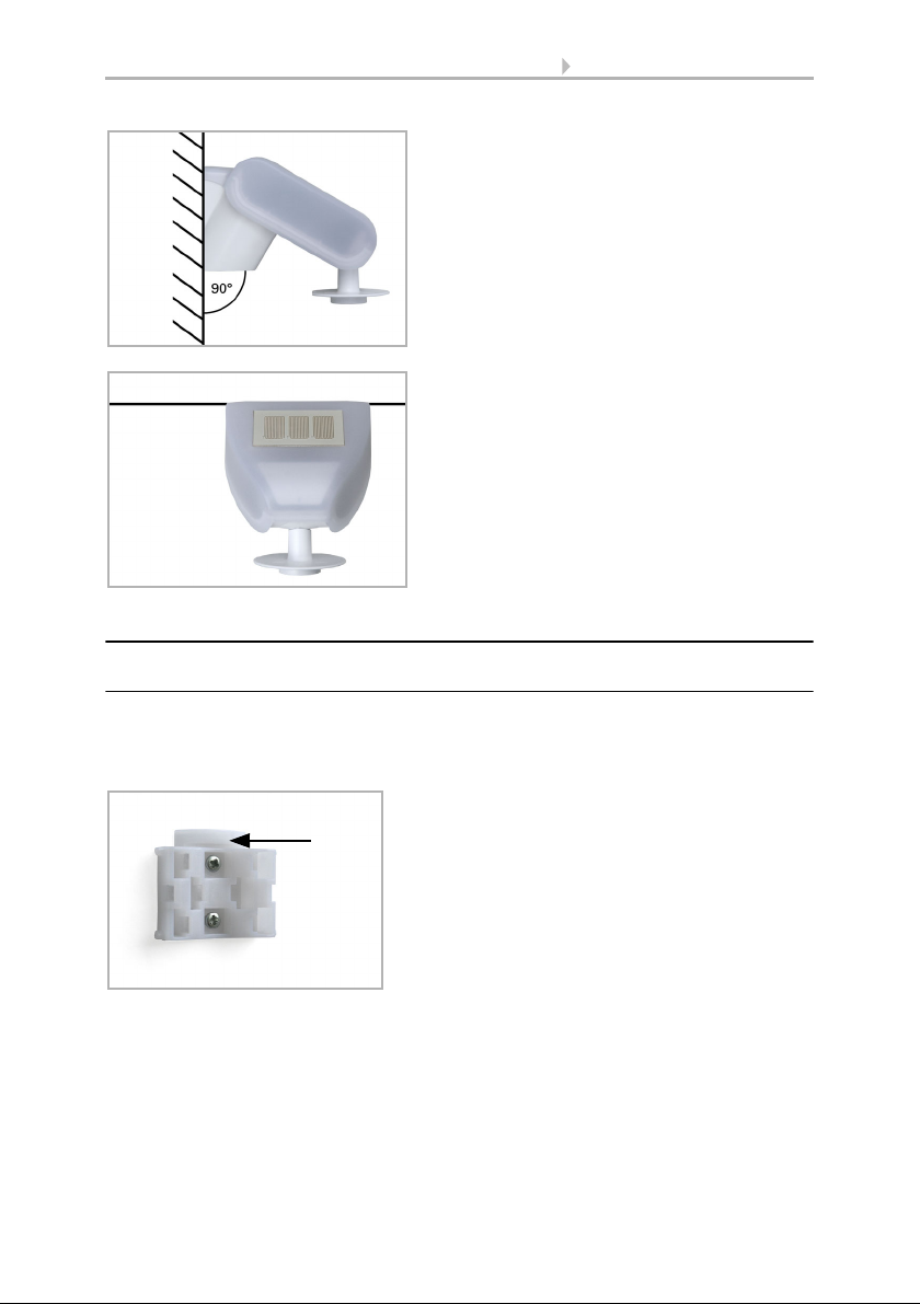
Fig. 2
The brightness/wind sensor must be mount-
ed on a vertical wall (or a pole).
Wall
or
pole
Fig. 3
The brightness/wind sensor must be mount-
ed in the horizontal transverse direction (hori-
zontally).
Horizontal
Fig. 4
When wall mounting: flat side on wall, crescent-
shaped collar upward.
Collar

7 Installation and commissioning
Brightness and Wind Sensor KNX LW • Status: 19.07.2019 • Technical changes reserved. Errors reserved.
2.3.2. View of rear side and drill hole plan
Fig. 5
When pole mounting: curved side on pole, collar
downward.
Collar
Fig. 6
Different mounting arms are available from Els-
ner Elektronik as additional, optional accessories
for flexible installation of the weather station on
a wall, pole or beam.
Example of the use of a mounting arm:
Due to flexible ball joints, the sensor can be
brought into ideal position.
Fig. 7
Example use of the hinge arm mounting:
Fitting to a pole with worm drive hose clips
Slot hole 7,5 x 5 mm
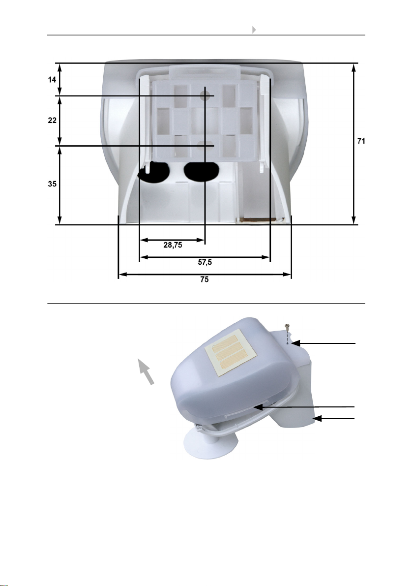
Fig. 8 a+b
Drill hole plan
Dimensions of rear side of
housing with bracket. Sub-
ject to change for technical
enhancement.
8 Installation and commissioning
Brightness and Wind Sensor KNX LW • Status: 19.07.2019 • Technical changes reserved. Errors reserved.
2.3.3. Preparing the sensor
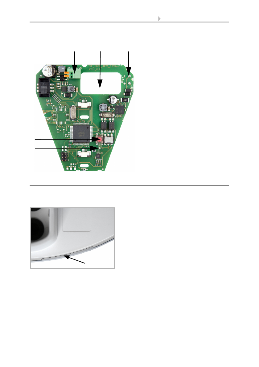
The sensor cover snaps in on the left and right along the bottom edge (see Fig.). The
cover of the 230V model is also screwed on top. Remove the cover. Proceed carefully,
so as not to pull off the wire connecting the PCB in the bottom part with the cover (sol-
dered cable connection in case of 230 V AC version, cable with plug in case of 12...40 V
DC / 12...28 V AC version).
Fig. 9
1 Screw-on cover (230V de-
vice)
2 Cover snaps
3 Bottom part of housing
2
3
Unsnap cover
and remove upwards
1
9 Installation and commissioning
Brightness and Wind Sensor KNX LW • Status: 19.07.2019 • Technical changes reserved. Errors reserved.
Lead the cable for the voltage supply and bus connection through the rubber seals on
the bottom of the device and connect Voltage L/N and Bus +/- to the terminals provid-
ed.
2.3.4. PCB layout
230 V AC version
Fig. 10
Remove the cable shielding under the circuit
board and only feed the connector cables up-
wards through the openings in the circuit
board.
Fig. 11
1 Opening for the cable for the
voltage supply
2 Tension clamp for voltage
supply (230 V AC),
suitable for massive conduc-
tors of up to 1.5 mm² or con-
ductors with fine wires
3 Opening for bus cable
4SlotforKNXclamp+/-
5 Programming pushbutton for
the teach-in of the device
6 Programming LED
1
2
5
6
3 4
10 Installation and commissioning
Brightness and Wind Sensor KNX LW • Status: 19.07.2019 • Technical changes reserved. Errors reserved.
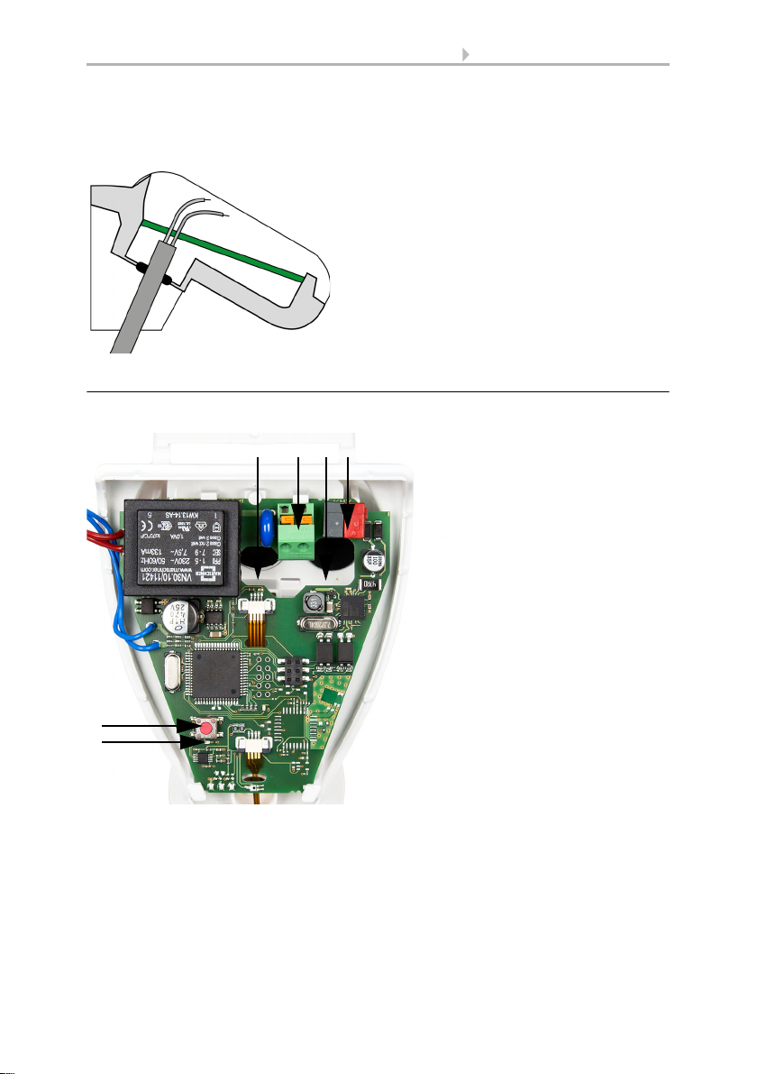
12...40 V DC / 12...28 V AC version
2.3.5. Mounting the weather station
Close the housing by putting the cover back over the bottom part. The cover must snap
in on the left and right with a definite “click”.
Fig. 12
1 Tension clamp for voltage
supply (12...40 V DC, 12...28 V
AC).
Massive conductors of up to
1.5 mm² or conductors with
fine wires. Terminal configu-
ration independent from po-
larity (+/- or -/+).
2 Opening for the cable for the
voltage supply and for bus ca-
ble
3SlotforKNXclamp+/-
4 Programming pushbutton for
the teach-in of the device
5 Programming LED
12
4
5
3
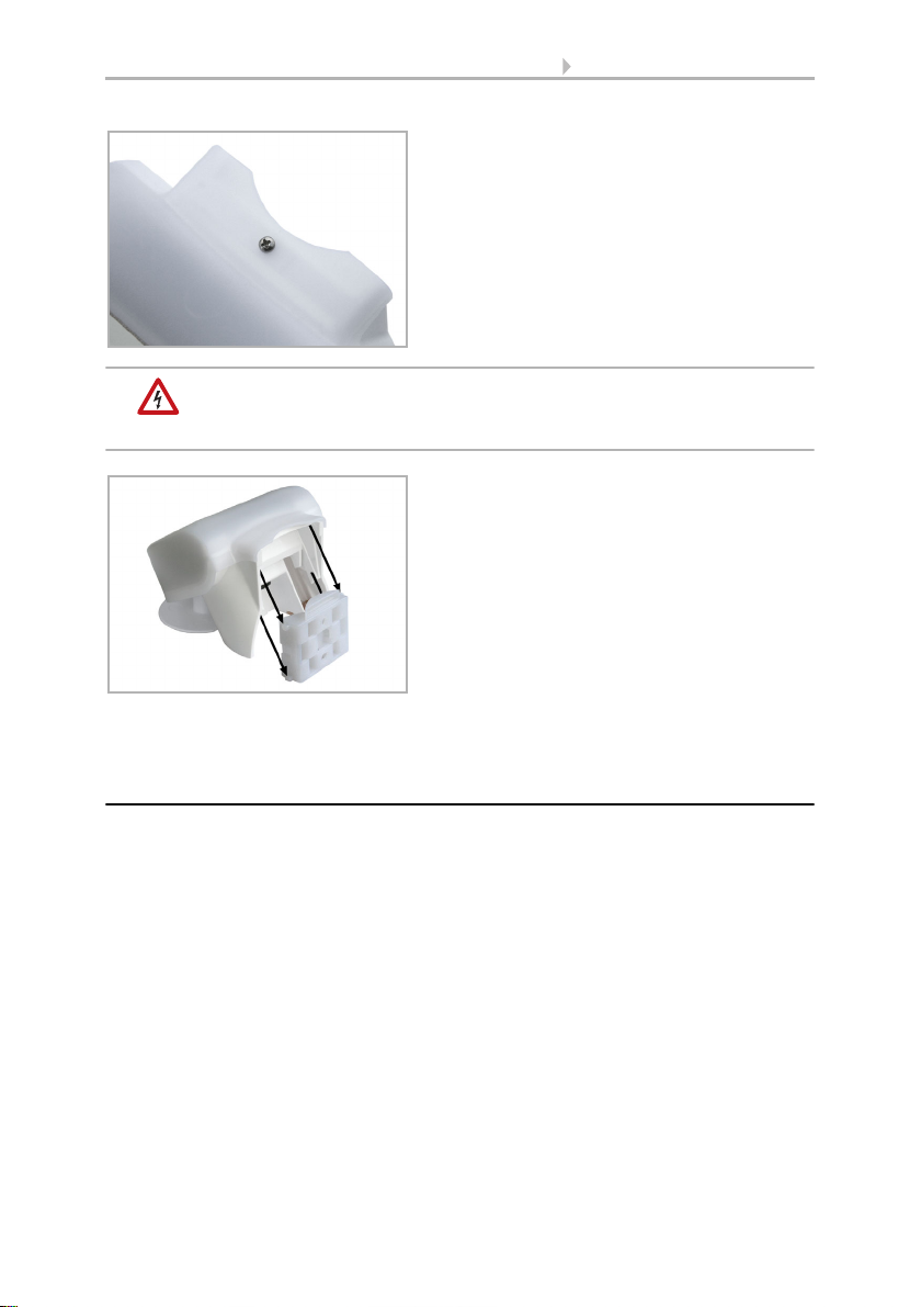
Fig. 13
Make sure the cover and bottom part are
properly snapped together! This picture is
looking at the closed sensor from under-
neath.
Fastening
11 Installation and commissioning
Brightness and Wind Sensor KNX LW • Status: 19.07.2019 • Technical changes reserved. Errors reserved.
DANGER!
There is a risk to life from the live voltage on a 230 V device!
• The cover must be screwed on in operation.
To remove it, the weather station can be simply pulled upwards out of the mount,
against the resistance of the fastening.
2.4. Notes on mounting and commissioning
Do not open the device if water (rain) might ingress: even some drops might damage
the electronic system.
Observe the correct connections. Incorrect connections may destroy the sensor or con-
nected electronic devices.
The measured wind value and thus all other wind switching outputs may only be sup-
plied 60 seconds after the supply voltage has been connected.
After the auxiliary voltage has been applied, the device will enter an initialisation phase
lasting a few seconds. During this phase no information can be received or sent via the
bus.
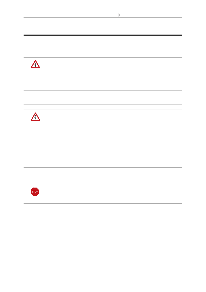
Fig. 14
With the 230V model, screw the cover on to
the underpart, to prevent unauthorised or ac-
cidental opening.
Fig. 15
Push the housing from above into the fas-
tened mount. The bumps on the mount must
snap into the rails in the housing.
12 Addressing of the device at the bus
Brightness and Wind Sensor KNX LW • Status: 19.07.2019 • Technical changes reserved. Errors reserved.
3. Addressing of the device at the bus
The device is supplied with the bus address 15.15.250. You can program another ad-
dress into the ETS by overwriting the 15.15.250 address or by teaching via the pro-
gramming key on the circuit board inside the housing.
DANGER!
Risk to life from live voltage (mains voltage)!
• With the 230V model, bus addressing via the programming key
should only be done by an accredited electrician.
• Do not touch any components on the circuit board while pressing
the key.
4. Maintenance
DANGER!
There is a risk to life from the live voltage (mains voltage)!
If you come into contact with live components in the device,
(e.g. caused also by a jet of water) there is the risk of an electric
shock with 230 V devices.
Risk of injury caused by components moved automatically!
The automatic control can start system components and place people
in danger (e.g. moving windows/awnings if a rain/wind alarm has
been triggered while cleaning).
• Always isolate the device from the mains for servicing and cleaning
(e. g. switch off or remove the fuse).
The device must regularly be checked for dirt twice a year and cleaned if necessary. In
case of severe dirt, the sensor may not work properly anymore.
ATTENTION
The device can be damaged if water penetrates the housing.
• Do not clean with high pressure cleaners or steam jets.

13 Transmission protocol
Brightness/Wind Sensor KNX LW • Status: 19.07.2019 • Technical changes reserved. Errors reserved.
5. Transmission protocol
Units of measurement:
Wind in Metre per second
Brightness in Lux
5.1. List of all communication objects
Abbreviations EIS types:
1 Switching 1/0
5 Floating point value
6 8 bit value
Abbreviations flags:
C Communication
R Read
WWrite
T Transmit
Nr. Name Function EIS
type
Flags
0 Wind force measured value Output 5 C R T
1 Request max. wind force Input 1 C R W
2 Max. wind force measured value Output 5 C R T
3 Reset max. wind force Input 1 C R W
4 Wind sensor malfunction Output 1 C R T
5 Wind threshold value 1 16 bit value 5 C R W T
6 Wind threshold value 1 1 = Increment|
0 = Decrement
1CRW
7 Wind threshold value 1 Increment 1 C R W
8 Wind threshold value 1 Decrement 1 C R W
9 Wind threshold value 1 Switching output 1 C R T
10 Wind threshold value 1 Switching output
block
1CRW
11 Wind threshold value 2 16 bit value 5 C R W T
12 Wind threshold value 2 1 = Increment |
0 = Decrement
1CRW
13 Wind threshold value 2 Increment 1 C R W
14 Wind threshold value 2 Decrement 1 C R W
15 Wind threshold value 2 Switching output 1 C R T
16 Wind threshold value 2 Switching output
Sperre
1CRW
17 Wind threshold value 3 16 bit value 5 C R W T

14 Transmission protocol
Brightness/Wind Sensor KNX LW • Status: 19.07.2019 • Technical changes reserved. Errors reserved.
18 Wind threshold value 3 1 = Increment |
0 = Decrement
1CRW
19 Wind threshold value 3 Increment 1 C R W
20 Wind threshold value 3 Decrement 1 C R W
21 Wind threshold value 3 Switching output 1 C R T
22 Wind threshold value 3 Switching output
block
1CRW
23 AND Logic 1 Switching output 1 C R T
24 AND Logic 1 8 bit output A 6 C R T
25 AND Logic1 8 bit output B 6 C R T
26 AND Logic 2 Switching output 1 C R T
27 AND Logic 2 8 bit output A 6 C R T
28 AND Logic 2 8 bit output B 6 C R T
29 AND Logic 3 Switching output 1 C R T
30 AND Logic 3 8 bit output A 6 C R T
31 AND Logic 3 8 bit output B 6 C R T
32 AND Logic 4 Switching output 1 C R T
33 AND Logic 4 8 bit output A 6 C R T
34 AND Logic 4 8 bit output B 6 C R T
35 AND Logic 5 Switching output 1 C R T
36 AND Logic 5 8 bit output A 6 C R T
37 AND Logic 5 8 bit output B 6 C R T
38 AND Logic 6 Switching output 1 C R T
39 AND Logic 6 8 bit output A 6 C R T
40 AND Logic 6 8 bit output B 6 C R T
41 AND Logic7 Switching output 1 C R T
42 UND Logik 7 8 bit output A 6 C R T
43 AND Logic 7 8 bit output B 6 C R T
44 AND Logic8 Switching output 1 C R T
45 AND Logic 8 8 bit output A 6 C R T
46 AND Logic 8 8 bit output B 6 C R T
47 OR Logic 1 Switching output 1 C R T
48 OR Logic 1 8 bit output A 6 C R T
49 OR Logic 1 8 bit output B 6 C R T
50 OR Logic 2 Switching output 1 C R T
51 OR Logic 2 8 bit output A 6 C R T
52 OR Logic 2 8 bit output B 6 C R T
53 OR Logic 3 Switching output 1 C R T
54 OR Logic 3 8 bit output A 6 C R T
Nr. Name Function EIS
type
Flags

15 Transmission protocol
Brightness/Wind Sensor KNX LW • Status: 19.07.2019 • Technical changes reserved. Errors reserved.
55 OR Logic 3 8 bit output B 6 C R T
56 OR Logic4 Switching output 1 C R T
57 OR Logic 4 8 bit output A 6 C R T
58 OR Logic4 8 bit output B 6 C R T
59 OR Logic 5 Switching output 1 C R T
60 OR Logic 5 8 bit output A 6 C R T
61 OR Logic 5 8 bit output B 6 C R T
62 OR Logic 6 Switching output 1 C R T
63 OR Logic 6 8 bit output A 6 C R T
64 OR Logic 6 8 bit output B 6 C R T
65 OR Logic 7 Switching output 1 C R T
66 OR Logic 7 8 bit output A 6 C R T
67 OR Logic 7 8 bit output B 6 C R T
68 OR Logic 8 Switching output 1 C R T
69 OR Logic 8 8 bit output A 6 C R T
70 OR Logic 8 8 bit output B 6 C R T
71 Logic input 1 Input 1 C R W
72 Logic input 2 Input 1 C R W
73 Logic input 3 Input 1 C R W
74 Logic input 4 Input 1 C R W
75 Logic input 5 Input 1 C R W
76 Logic input 6 Input 1 C R W
77 Logic input 7 Input 1 C R W
78 Logic input 8 Input 1 C R W
79 Brightness measured value Output 5 C R T
80 Brightness threshold value 1 16 bit value 5 C R W T
81 Brightness threshold value 1 1 = Increment |
0 = Decrement
1CRW
82 Brightness threshold value 1 Increment 1 C R W
83 Brightness threshold value 1 Decrement 1 C R W
84 Brightness threshold value 1 Switching output 1 C R T
85 Brightness threshold value 1 Switching output
block
1CRW
86 Brightness threshold value 2 16 bit value 5 C R W T
87 Brightness threshold value 2 1 = Increment |
0 = Decrement
1CRW
88 Brightness threshold value 2 Increment 1 C R W
89 Brightness threshold value 2 Decrement 1 C R W
Nr. Name Function EIS
type
Flags

16 Transmission protocol
Brightness/Wind Sensor KNX LW • Status: 19.07.2019 • Technical changes reserved. Errors reserved.
90 Brightness threshold value 2 Switching output 1 C R T
91 Brightness threshold value 2 Switching output
block
1CRW
92 Brightness threshold value 3 16 bit value 5 C R W T
93 Brightness threshold value 3 1 = Increment |
0 = Decrement
1CRW
94 Brightness threshold value 3 Increment 1 C R W
95 Brightness threshold value 3 Decrement 1 C R W
96 Brightness threshold value 3 Switching output 1 C R T
97 Brightness threshold value 3 Switching output
block
1CRW
98 Twilight threshold value 1 16 bit value 5 C R W T
99 Twilight threshold value 1 1 = Increment |
0 = Decrement
1CRW
100 Twilight threshold value 1 Increment 1 C R W
101 Twilight threshold value 1 Decrement 1 C R W
102 Twilight threshold value 1 Switching output 1 C R T
103 Twilight threshold value 1 Switching output
block
1CRW
104 Twilight threshold value 2 16 bit value 5 C R W T
105 Twilight threshold value 2 1 = Increment |
0 = Decrement
1CRW
106 Twilight threshold value 2 Increment 1 C R W
107 Twilight threshold value 2 Decrement 1 C R W
108 Twilight threshold value 2 Switching output 1 C R T
109 Twilight threshold value 2 Switching output
block
1CRW
110 Twilight threshold value3 16 bit value 5 C R W T
111 Twilight threshold value3 1 = Increment |
0 = Decrement
1CRW
112 Twilight threshold value 3 Increment 1 C R W
113 Twilight threshold value 3 Decrement 1 C R W
114 Twilight threshold value 3 Switching output 1 C R T
115 Twilight threshold value 3 Switching output
block
1CRW
116 Software Version readable 6 CR
Nr. Name Function EIS
type
Flags
17 Setting of parameters
Brightness/Wind Sensor KNX LW • Status: 19.07.2019 • Technical changes reserved. Errors reserved.
6. Setting of parameters
6.1. General settings
Wind force
Brightness
6.2. Threshold values
Wind force
Brightness
Maximum telegram quota 1 • 2 • 3 • 5 • 10 • 20 telegrams per second
Measured value • do not send
• send cyclically
• send on change
• send on change and cyclically
send cyclically every
(only if sending “cyclically“)
5 sec … 2 h
From change in %
(only if sending “on change“)
1 … 50; 20
Send and reset of the maximum wind load
value on request
not release • release
Use malfunction object No • Yes
Measured value • do not send
• send cyclically
• send on change
• send on change and cyclically
send cyclically every
(only if sending “cyclically“)
5 sec … 2 h
From change in %
(only if sending “on change“)
1 … 50; 20
Use threshold value 1 / 2 / 3 No • Yes
Transmission delay of the switching out-
puts after power up and programming
5 sec … 2 h
Transmission delay of the switching out-
puts after power up and programming
5 sec … 2 h
Use threshold value 1 / 2 / 3 No • Yes
Transmission delay of the switching out-
puts after power up and programming
5 sec … 2 h
Transmission delay of the switching out-
puts after power up and programming
5 sec … 2 h

18 Setting of parameters
Brightness/Wind Sensor KNX LW • Status: 19.07.2019 • Technical changes reserved. Errors reserved.
Twilight
6.2.1. Wind threshold value 1 / 2 / 3
Threshold value
If the threshold value is set per Parameter:
If the threshold value is set per Communication object:
Switching output
Use threshold value 1 / 2 / 3 No • Yes
Transmission delay of the switching out-
puts after power up and programming
5 sec … 2 h
Transmission delay of the switching out-
puts after power up and programming
5 sec … 2 h
Threshold value setpoint per Parameter • Communication object
Threshold value in 0,1 m/s 0 … 350; 40
Hysteresis of the threshold value in % 0 … 250; 20
The value communicated last shall be
maintained
• not
• after restoration of voltage
(the changes threshold value may be
saved at least 100,000 times)
• after restoration of voltage and
programming (Attention: Do not use
for first commissioning)
Start threshold value in 0,1 m/s
valid until 1. communication
(only if the value communicated last is
„not“ maintained or „after restoration of
voltage“)
0 … 350; 40
Type of threshold change • Absolute value with a 16 bit
communication object
• Increment / decrement with one
communication object
• Increment / decrement with two
communication objects
Step size
(only if sending „Increment/decrement“)
0,1 m/s … 5 m/s; 1 m/s
Hysteresis of the threshold value in % 0 … 250; 20
Output is at
(TV = Threshold Value)
• TV above = 1 | TV - Hyst. below = 0
• TV above = 0 | TV - Hyst. below= 1
• TV below = 1 | TV + Hyst. above = 0
• TV below = 0 | TV + Hyst. above = 1
Switching delay from 0 to 1 none • 1 sec … 2 h
Switching delay from 1 to 0 none • 1 sec … 2 h
This manual suits for next models
2
Table of contents
Other Elsner Accessories manuals

Elsner
Elsner KNX T-UP gl Guide

Elsner
Elsner KNX L User manual

Elsner
Elsner Vari KNX 3L Guide

Elsner
Elsner 71300 Guide

Elsner
Elsner KNX AQS/TH-B-UP Series Guide

Elsner
Elsner Cala KNX AQS/TH Guide

Elsner
Elsner KNX VOC-UP basic Guide

Elsner
Elsner KNX AQS/TH Guide

Elsner
Elsner Sewi KNX TH-L-Pr Guide

Elsner
Elsner KNX R Guide


