Elsner Vari KNX 3L Guide
Vari KNX 3L, Vari KNX 3L-T,
Vari KNX 3L-TH, Vari KNX 3L-TH-D,
Vari KNX 3L-TH-D GPS
Combined brightness sensors
Item numbers
70382 Vari KNX 3L
70383 Vari KNX 3L-T
70384 Vari KNX 3L-TH
70389 Vari KNX 3L-TH-D
70390 Vari KNX 3L-TH-D GPS
EN
Installation and Adjustment


1 Contents
Elsner Elektronik GmbH • Sohlengrund 16 • 75395 Ostelsheim • Germany
Sensors Vari KNX 3L • from ETS programme version 1.0
Status: 18.06.2019 • Errors excepted. Subject to technical changes.
1. Description ........................................................................................... 5
1.0.1. Scope of delivery .......................................................................................... 6
1.1. Technical specification ............................................................................................. 6
2. Installation and start-up ....................................................................... 9
2.1. Installation notes ...................................................................................................... 9
2.2. Installation location .................................................................................................. 9
2.3. Device design ......................................................................................................... 11
2.4. Installing the device ............................................................................................... 12
2.4.1. Preparation for installation ........................................................................ 12
2.4.2. Fitting the lower part of the housing with mounting ............................... 12
2.4.3. Connection .................................................................................................. 14
2.4.4. Completing the installation ........................................................................ 15
3. Addressing the device ........................................................................ 15
4. Maintenance ....................................................................................... 16
5. Transfer protocol ............................................................................... 17
5.1. List of all communication objects ......................................................................... 17
6. Parameter setting .............................................................................. 43
6.1. Behaviour on power failure/ restoration of power .............................................. 43
6.1.1. Storage of threshold values ....................................................................... 43
6.1.2. Malfunction objects .................................................................................... 43
6.1.3. General settings .......................................................................................... 43
6.2. GPS .......................................................................................................................... 44
6.3. Location ................................................................................................................... 45
6.4. Temperature Measurement ................................................................................... 47
6.5. Temperature threshold values .............................................................................. 48
6.5.1. Threshold values 1-4 .................................................................................. 48
6.6. Brightness measurement value ............................................................................ 51
6.7. Brightness threshold values sensor 1-3 and total brightness threshold values 51
6.7.1. Threshold values 1-4 .................................................................................. 52
6.8. Twilight brightness threshold values ................................................................... 54
6.8.1. Threshold values 1-4 .................................................................................. 54
6.9. Night ........................................................................................................................ 56
6.10.Sun position ........................................................................................................... 57
6.11.Humidity Measurement ......................................................................................... 57
6.12.Humidity threshold values .................................................................................... 58
6.12.1. Threshold values 1-4 .................................................................................. 58
6.13.Dewpoint measurement ........................................................................................ 61
6.13.1. Cooling medium temperature monitoring ............................................... 61
6.14.Absolute humidity ................................................................................................. 63
6.15.Comfort field .......................................................................................................... 64
6.16.Air pressure measurement ................................................................................... 65
6.17.Wind threshold values ........................................................................................... 66

2 Contents
Elsner Elektronik GmbH • Sohlengrund 16 • 75395 Ostelsheim • Germany
Sensors Vari KNX 3L • from ETS programme version 1.0
Status: 18.06.2019 • Errors excepted. Subject to technical changes.
6.17.1. Wind threshold values 1-4 ......................................................................... 66
6.18.Temperature PI control .......................................................................................... 68
6.18.1. Heating control level 1/2 ............................................................................. 74
6.18.2. Cooling control level 1/2 ............................................................................. 76
6.19.Summer Compensation ........................................................................................ 78
6.20.Humidity PI control ................................................................................................ 79
6.21.Variable comparator .............................................................................................. 82
6.21.1. Control variable comparator 1/2/3/4 .......................................................... 82
6.22.Computer ................................................................................................................ 83
6.22.1. Computers 1-8 ............................................................................................. 83
6.23.Weekly timer .......................................................................................................... 87
6.23.1. Weekly timer period 1-24 ........................................................................... 87
6.24.Calendar timer ........................................................................................................ 88
6.24.1. Calendar clock Period 1-4 ........................................................................... 89
6.25.Logic ........................................................................................................................ 90
6.25.1. AND logic 1-8 and OR logic outputs 1-8 ................................................... 90
6.25.2. AND logic connection inputs ..................................................................... 92
6.25.3. Connection inputs of the OR logic ............................................................. 97
3 Clarification of signs
This manual is amended periodically and will be brought into line with new software
releases. The change status (software version and date) can be found in the contents footer.
If you have a device with a later software version, please check
www.elsner-elektronik.de in the menu area "Service" to find out whether a more up-to-
date version of the manual is available.
Clarification of signs used in this manual
Installation, inspection, commissioning and troubleshooting of the device
must only be carried out by a competent electrician.
Safety advice.
Safety advice for working on electrical connections, components,
etc.
DANGER! ... indicates an immediately hazardous situation which will lead to
death or severe injuries if it is not avoided.
WARNING! ... indicates a potentially hazardous situation which may lead to
death or severe injuries if it is not avoided.
CAUTION! ... indicates a potentially hazardous situation which may lead to
trivial or minor injuries if it is not avoided.
ATTENTION! ... indicates a situation which may lead to damage to property if it is
not avoided.
ETS In the ETS tables, the parameter default settings are marked by
underlining.

4 Clarification of signs

5 Description
Sensors Vari KNX 3L • Version: 18.06.2019 • Technical changes and errors excepted.
1. Description
The Sensors Vari KNX 3L for the KNX building bus system record brightness (sun)
and additionally temperature, air humidity and air pressure outside, depending on the
model. The model Vari KNX 3L-TH-D GPS also receives the GPS signal for time and lo-
cation and uses it to compute the position of the sun (azimuth and elevation).
The measurement values can be used for the control of limit-dependent switching out-
puts. States can be linked via AND logic gates and OR logic gates. Multi-function mod-
ules change input data as required by means of calculations, querying a condition, or
converting the data point type.
Models with a temperature sensor have an integrated PI controller for heating/cooling.
Models with humidity sensor have a PI controller for ventilation.
The compact housing of the Vari KNX 3L accommodates the sensors, evaluation cir-
cuits and bus-coupling electronics.
Functions 70382 Vari KNX 3L:
•Brightness measurement: The current light intensity is measured by three
sensors. Of the three measurement values, the maximum value or a calculated
mixed value can be output optionally.
•Switching outputs for all measured and computed values. Threshold values
can be adjusted per parameter or via communication objects
•8 AND and 8 OR logic gates, each with 4 inputs. All switching events as well
as 16 logic inputs (in the form of communications objects) can be used as
inputs for the logic gates. The output of each gate can be configured optionally
as 1-bit or 2 x 8-bit
•8 multi-function modules (computers) for changing the input data by
calculations, by querying a condition or by converting the data point type
Additional functions of the models with temperature sensor:
(70383 Vari KNX 3L-T, 70384 Vari KNX 3L-TH,
70389 Vari KNX 3L-TH-D, 70390 Vari KNX 3L-TH-D GPS)
•Temperature measurement with mixed value calculation. The share of
internal measurement value and external value can be set as a percentage
•PI-controller for heating (one or two-stage) and cooling (one or two-stage)
according to temperature. Regulation according to separate setpoints or basic
setpoint temperature
•Summer compensation for cooling systems. A characteristic curve matches
the target temperature in the room to the external temperature and sets the
minimum and maximum target temperature values
Additional functions of the models with humidity sensor:
(70384 Vari KNX 3L-TH, 70389 Vari KNX 3L-TH-D, 70390 Vari KNX 3L-TH-D GPS)
•Humidity measurement (relative, absolute), with Mixed value calculation.
The share of internal measurement value and external value can be set as a
percentage.

6 Description
Sensors Vari KNX 3L • Version: 18.06.2019 • Technical changes and errors excepted.
In addition the bus output will indicate whether the values are inside the
comfort field (DIN 1946). The dewpoint will be calculated
•PI controller for humidity according to humidity: Ventilate/Air (one-stage) or
Ventilate (one or two-stage)
•4 control variable comparators to output minimum, maximum or average
values. 5 inputs each for values received via communication objects
Additional functions of the models with air pressure sensor:
(70389 Vari KNX 3L-TH-D, 70390 Vari KNX 3L-TH-D GPS)
• Air pressure measurement: Output of the value as normal pressure and
optionally as barometric pressure
Additional functions 70390 Vari KNX 3L-TH-D GPS:
•GPS receiver, outputting the current time and location coordinates. The
Sensor Vari KNX 3L-TH-D GPS also computes the position of the sun
(azimuth and elevation)
Configuration is made using the KNX software ETS. The product file can be down-
loaded from the Elsner Elektronik website on www.elsner-elektronik.de in the “Ser-
vice” menu.
1.0.1. Scope of delivery
•Sensor
• Stainless steel installation band for pole installation
• 4×50 mm stainless steel Roundhead screws and 6×30 mm dowels for wall
mounting. Use fixing materials that are suitable for the base!
1.1. Technical specification
Housing Plastic
Colour White / Translucent
Assembly Surface mount
Protection category IP 44
Dimensions approx. 65 × 80 × 30 (W × H × D, mm)
Weight approx. 60 g
Operating voltage KNX bus voltage
Bus current max. 20 mA
Data output KNX +/- bus connector terminal
BCU type Integrated micro controller
PEI type 0
Group addresses max. 2000
Assignments max. 2000
Brightness sensor:
Measurement range 0 lux … 150,000 lux

7 Description
Sensors Vari KNX 3L • Version: 18.06.2019 • Technical changes and errors excepted.
Vari KNX 3L-TH-D GPS:
Vari KNX 3L-TH-D:
Resolution 1 lux up to 300 lux
2 lux up to 1,000 lux
25 lux up to 150,000 lux
Accuracy ±15% of the measurement value at 30 lux … 30,000 lux
Ambient temperature Operation -25…+80°C, Storage -40…+85°C,
avoid condensation
Communication objects: 603
Temperature sensor:
Measurement range -25°C … +80°C
Resolution 0.1°C
Accuracy ±0,8°C at -25...-10°C
±0,5°C at -10...+65°C
±0,6°C at +65...+80°C
Humidity sensor:
Measurement range 0% RH … 100% RH
Resolution 0.1% RH
Accuracy ±7,5% RH at 0...10% RH
±4,5% RH at 10...90% RH
±7,5% RH at 90...100% RH
Pressure sensor:
Measurement range 300 mbar … 1100 mbar
Resolution 0.1 mbar
Accuracy ±4 mbar
Ambient temperature Operation -25…+80°C, Storage -40…+85°C,
avoid condensation
Communication objects: 455
Temperature sensor:
Measurement range -25°C … +80°C
Resolution 0.1°C
Accuracy ±0,8°C at -25...-10°C
±0,5°C at -10...+65°C
±0,6°C at +65...+80°C
Humidity sensor:
Measurement range 0% RH … 100% RH
Resolution 0.1% RH
Accuracy ±7,5% RH at 0...10% RH
±4,5% RH at 10...90% RH
±7,5% RH at 90...100% RH
Pressure sensor:

8 Description
Sensors Vari KNX 3L • Version: 18.06.2019 • Technical changes and errors excepted.
Vari KNX 3L-TH:
Vari KNX 3L-T:
Vari KNX 3L:
The product conforms with the provisions of EU directives.
Measurement range 300 mbar … 1100 mbar
Resolution 0.1 mbar
Accuracy ±4 mbar
Ambient temperature Operation -25…+80°C, Storage -40…+85°C,
avoid condensation
Communication objects: 421
Temperature sensor:
Measurement range -25°C … +80°C
Resolution 0.1°C
Accuracy ±0,8°C at -25...-10°C
±0,5°C at -10...+65°C
±0,6°C at +65...+80°C
Humidity sensor:
Measurement range 0% RH … 100% RH
Resolution 0.1% RH
Accuracy ±7,5% RH at 0...10% RH
±4,5% RH at 10...90% RH
±7,5% RH at 90...100% RH
Ambient temperature Operation -30…+50°C, Storage -30…+70°C
Communication objects: 339
Temperature sensor:
Measurement range -30°C … +50°C
Resolution 0.1°C
Accuracy ±0,5°C at -30...+25°C
±1,5°C at -30...+45°C
Ambient temperature Operation -30…+50°C, Storage -30…+70°C
Communication objects: 274

9 Installation and start-up
Sensors Vari KNX 3L • Version: 18.06.2019 • Technical changes and errors excepted.
2. Installation and start-up
2.1. Installation notes
Installation, testing, operational start-up and troubleshooting should
only be performed by an electrician.
CAUTION!
Live voltage!
There are unprotected live components inside the device.
• National legal regulations are to be followed.
• Ensure that all lines to be assembled are free of voltage and take
precautions against accidental switching on.
• Do not use the device if it is damaged.
• Take the device or system out of service and secure it against
unintentional use, if it can be assumed, that risk-free operation is no
longer guaranteed.
The device is only to be used for its intended purpose. Any improper modification or
failure to follow the operating instructions voids any and all warranty and guarantee
claims.
After unpacking the device, check it immediately for possible mechanical damage. If it
has been damaged in transport, inform the supplier immediately.
The device may only be used as a fixed-site installation; that means only when assem-
bled and after conclusion of all installation and operational start-up tasks and only in
the surroundings designated for it.
Elsner Elektronik is not liable for any changes in norms and standards which may occur
after publication of these operating instructions.
2.2. Installation location
Due to the GPS receiver, the Sensor Vari KNX 3L-TH-D GPS must be installed out-
side. The other models can be mounted outside or inside.
The Vari KNX 3L-TH-D GPS, Vari KNX 3L-TH-D and Vari KNX 3L-TH should be
protected from condensation. For critical applications in which the formation of con-
densation is expected, please consult Elsner Elektronik about special solutions.
10 Installation and start-up
Sensors Vari KNX 3L • Version: 18.06.2019 • Technical changes and errors excepted.
Select an installation position on the building where the sensors can measure sunshine
without any obstructions. The weather station should not be shaded by structures or,
for example, trees. Ensure no shadow is thrown on the device by an extended awning.
Note for devices with temperature sensor:
Temperature measurements can also be distorted by external influences such as
warming or cooling of the building structure on which the sensor is mounted (sunlight,
heating or cold water pipes). Temperature variations from such sources of interference
must be corrected in the ETS in order to ensure the specified accuracy of the sensor
(temperature offset).
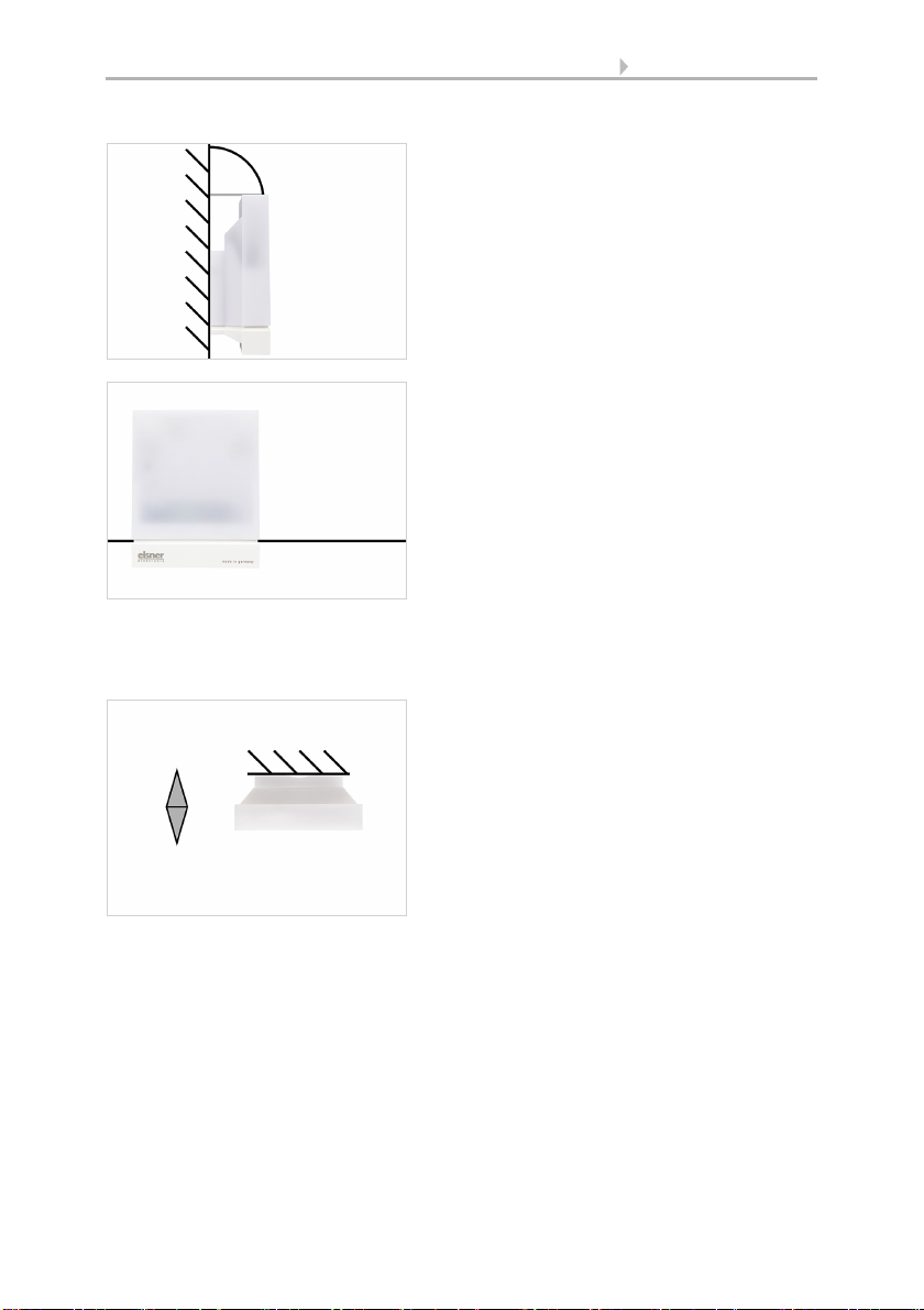
Fig. 1
The device must be attached to a vertical wall
(or a pole).
wall
or
pole
90°
Fig. 2
The device must be mounted in the horizontal
(transverse) direction.
Horizontal
Fig. 3
For installation in the northern hemisphere,
the device must be aligned to face south.
For installation in the southern hemisphere,
the device must be aligned to face north.
North
South
Wall/Pole
11 Installation and start-up
Sensors Vari KNX 3L • Version: 18.06.2019 • Technical changes and errors excepted.
Note for devices with GPS receiver:
Magnetic fields, transmitters and interference fields from electrical consumers (e.g. flu-
orescent lamps, neon signs, switch mode power supplies etc.) can block or interfere
with the reception of the GPS signal.
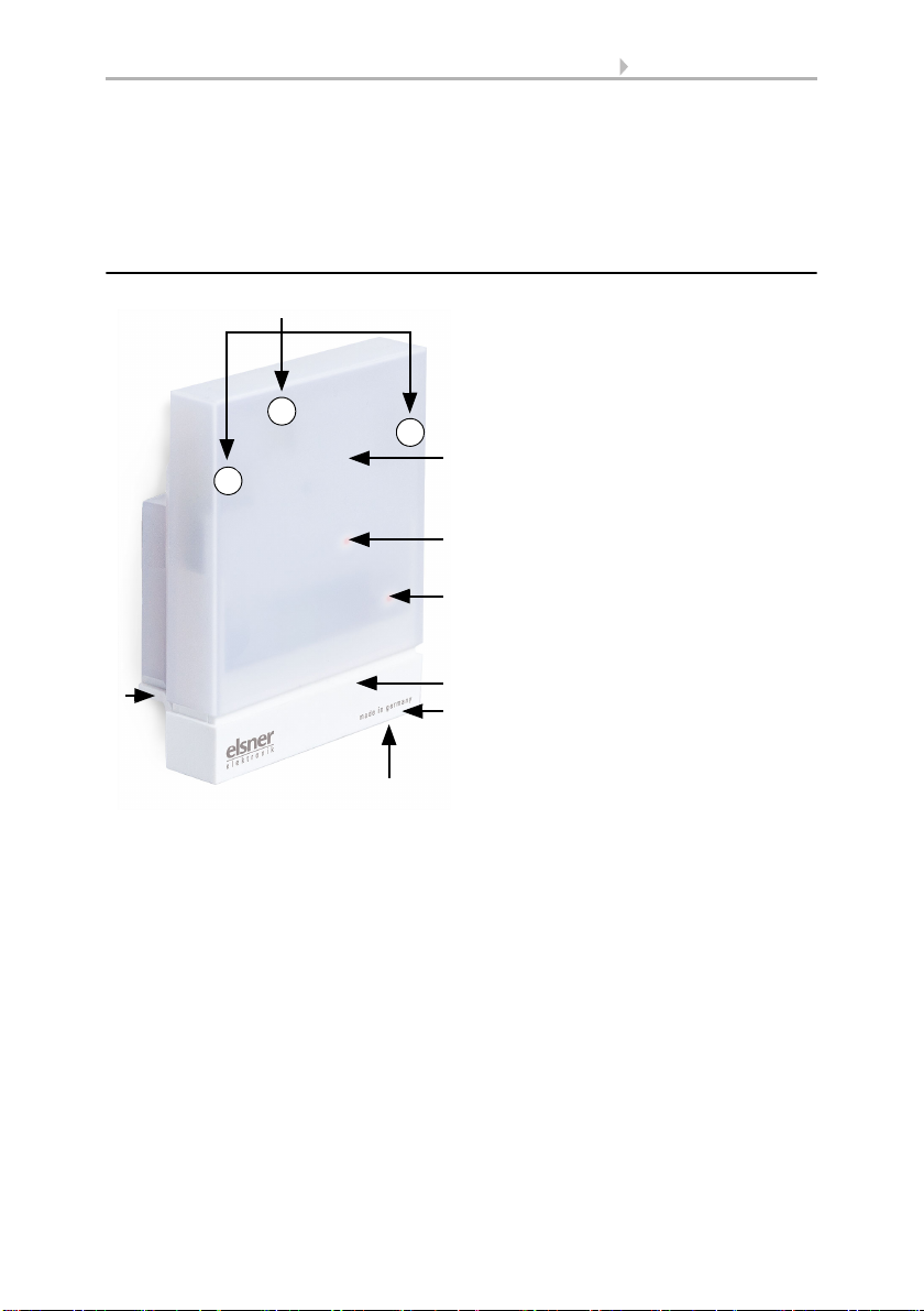
2.3. Device design
3
Fig. 4
1 Position of the brightness sen-
sors 1-3. With alignment of the
device to the south
Sensor 1 = West
Sensor 2 = South
Sensor 3 = East
2 Semi-transparent cover
Vari KNX TH-D GPS: GPS receiv-
er and pressure sensor below.
Vari KNX TH-D: pressure sensor
below.
3 Position of the Signal LED (un-
der the cover). LED is freely con-
trolled via two objects
4
8
7
1
5
2
6
1
3
2
4 Position of the programming LED (under the cover)
5 Lower part of housing
6 Temperature and humidity sensor for Vari KNX 3L-TH-D GPS, Vari KNX 3L-TH-D,
Vari KNX 3L-TH.
Temperature sensor for Vari KNX 3L-T.
7 Programming key on the bottom of the housing (recessed), see Addressing the de-
vice
8 Wall/Pole holder

12 Installation and start-up
Sensors Vari KNX 3L • Version: 18.06.2019 • Technical changes and errors excepted.
2.4. Installing the device
ATTENTION!
Even a few drops of water can damage the device electronics.
• Do not open the device if water (e.g. rain) can get into it.
2.4.1. Preparation for installation
2.4.2. Fitting the lower part of the housing with mounting
Now, first of all, assemble the lower part of the housing with the integrated mounting
for wall or pole installation.
Wall installation
Use fixing materials (dowels, screws) that are suitable for the base.
Fig. 5
The cover and lower part of the housing are
connected together. Pull both parts apart in a
straight line.
Fig. 6
The device is installed with two screws. Break
off the two longitudinal holes in the housing.
Longitudinal holes
Fig. 7 a+b
a) If the power lead is to be hidden when in-
stalled, it must emerge from the wall in
the vicinity of the rear of the housing
(marked area).
13 Installation and start-up
Sensors Vari KNX 3L • Version: 18.06.2019 • Technical changes and errors excepted.
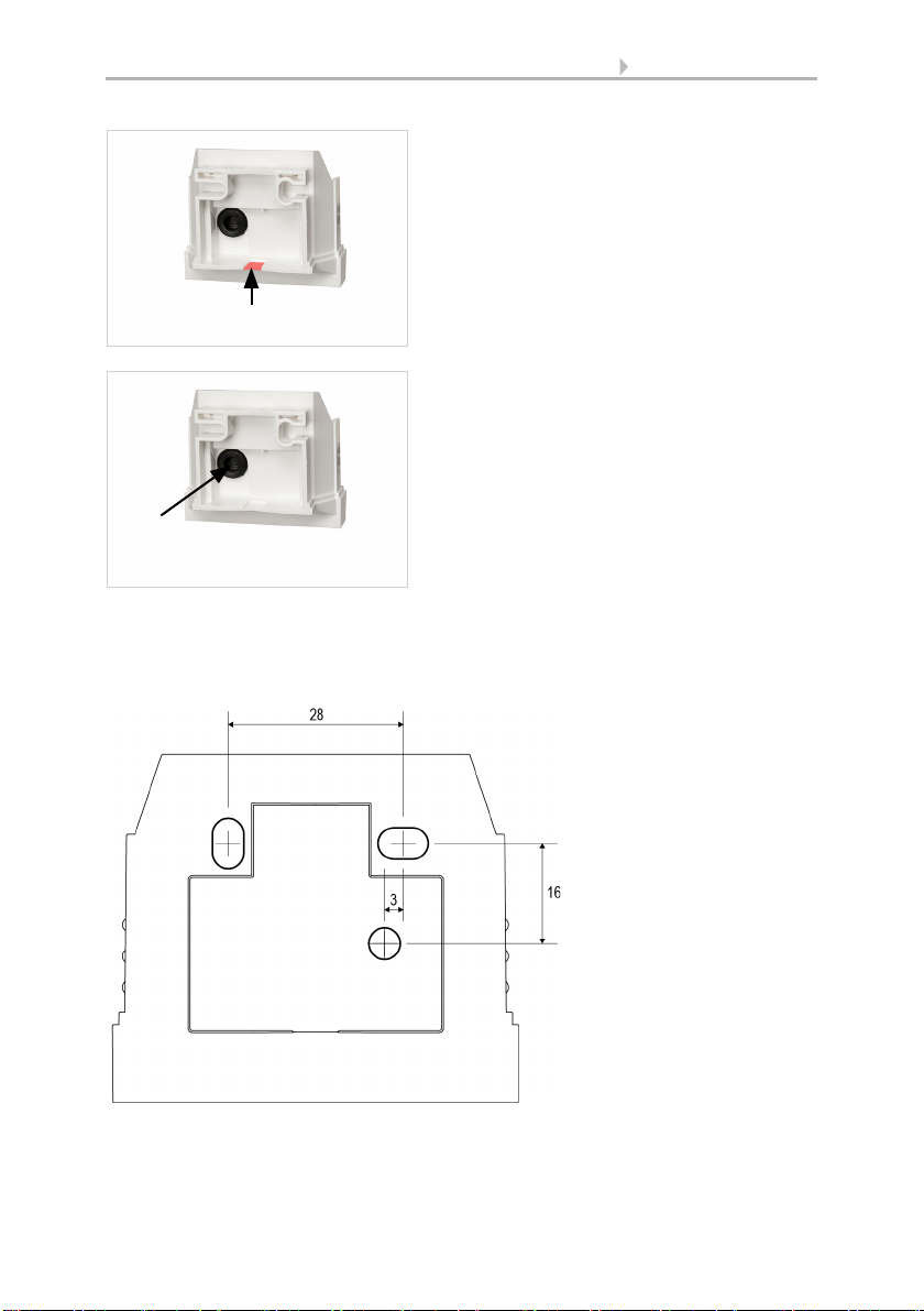
Drilling plan
ATTENTION! The print out of the data sheet doesn‘t have original size!
A separate, dimensionally correct drilling plan is included ex works and this can be
used as a template.
b) If the power lead is to be surface-mount-
ed, the cable guide is broken off. The lead
is then fed into the device from the bot-
tom of the housing.
Cable guide
Fig. 8
Feed the power lead through the rubber gas-
ket.
Rubber
gasket
Fig. 9
Dimensions in mm. Varia-
tions are possible for tech-
nical reasons
A/B2× longitudinal holes
8 mm × 5 mm
C Position of the cable
outlet (rubber gasket)
in the housing
AB
C

14 Installation and start-up
Sensors Vari KNX 3L • Version: 18.06.2019 • Technical changes and errors excepted.
Pole installation
The device is installed on the pole with the enclosed stainless steel mounting band.
2.4.3. Connection
The connector is in the lower part of the housing.
Fig. 10
Feed the mounting band through the eyelets
in the lower part of the housing.
Fig. 11
Break the cable guide off.
Feed the power lead through the rubber gas-
ket.
Rubber
gasket Cable guide
Fig. 12
Connect the device to the KNX bus via
the pluggable terminal (+|-).
-
+
-
+
KNX
15 Addressing the device
Sensors Vari KNX 3L • Version: 18.06.2019 • Technical changes and errors excepted.
2.4.4. Completing the installation
3. Addressing the device
The device is delivered ex works with the bus address 15.15.255. You can program a
different address in the ETS by overwriting the address 15.15.255 or by teaching the
device via the programming button.
The programming button can be reached through the opening on the underside of the
housing; it is recessed by approx. 8 mm. Use a thin object to reach the button, e.g. a
1.5 mm² wire.
Fig. 13
Put the cover on the lower part. This also
makes the plug-in connection between the
board in the cover and the socket in the lower
part.
Fig. 14 a+b
1 Programming LED (under the semi-
transparent cover)
2 Programming button for teaching
the device
12
2Housing from below
16 Maintenance
Sensors Vari KNX 3L • Version: 18.06.2019 • Technical changes and errors excepted.
4. Maintenance
WARNING!
Risk of injury due to automatically moved components!
The automatic control may cause parts of the system to start up and
pose a danger to humans.
• Always disconnect the system from the mains power before
maintenance or cleaning.
The device should be regularly checked twice a year for soiling and cleaned if required.
If there is major soiling, the function of the sensor may be compromised.
ATTENTION
The device may be damaged if water penetrates the housing.
• Do not clean with high pressure cleaners or steam jets.

17 Transfer protocol
Sensors Vari KNX 3L • Version: 18.06.2019 • Technical changes and errors excepted.
5. Transfer protocol
Units:
Temperatures in degrees Celsius
Brightness in Lux
Air pressure in Pascal
Azimuth and elevation in degrees
Air humidity in %
Absolute air humidity in g/kg and/or g/m3
Variables in %
5.1. List of all communication objects
Abbreviation flags:
C Communication
R Read
WWrite
T Transfer
UUpdate
No. Text Func-
tion
Flags DPT type Size
1 Software version Output R-CT [217.1] DPT_Ver-
sion
2 bytes
Models with GPS receiver only (70390)
21 Signal LED object 1s cycle Input -WC- [1.1] DPT_Switch 1 bit
22 Signal LED object 4s cycle Input -WC- [1.1] DPT_Switch 1 bit
24 GPS malfunction (0 : OK | 1: NOK) Output R-CT [1.2] DPT_Bool 1 bit
25 Date / time Output RWCT [19.1] DPT_Date-
Time
8 bytes
26 Date Output RWCT [11.1] DPT_Date 3 bytes
27 Time Output RWCT [10.1] DPT_-
TimeOfDay
3 bytes
28 Date and time query Input -WC- [1.017] DPT_Trig-
ger
1 bit
30 Location: Northern latitude [°] Output R-CT [14.7] DPT_Val-
ue_AngleDeg
4 bytes
31 Location: Eastern longitude [°] Output R-CT [14.7] DPT_Val-
ue_AngleDeg
4 bytes
Models with temperature sensor only (70383, 70384, 70389, 70390)
41 Temperature sensor: Malfunction Output R-CT [1.1] DPT_Switch 1 bit
42 Temperature sensor: External
measurement
Input -WCT [9.1] DPT_Val-
ue_Temp
2 bytes
43 Temperature sensor: Measured value Output R-CT [9.1] DPT_Val-
ue_Temp
2 bytes

18 Transfer protocol
Sensors Vari KNX 3L • Version: 18.06.2019 • Technical changes and errors excepted.
44 Temperature sensor: Total
measurement
Output R-CT [9.1] DPT_Val-
ue_Temp
2 bytes
45 Temperature sensor: Min./Max.
measurement query
Input -WC- [1.017] DPT_Trig-
ger
1 bit
46 Temperature sensor: Minimum
measurement
Output R-CT [9.1] DPT_Val-
ue_Temp
2 bytes
47 Temperature sensor: Maximum
measurement
Output R-CT [9.1] DPT_Val-
ue_Temp
2 bytes
48 Temperature sensor: Min./Max.
measurement reset
Input -WC- [1.017] DPT_Trig-
ger
1 bit
51 Temp. threshold value 1: Absolute
value
Input/
Output
RWCT [9.1] DPT_Val-
ue_Temp
2 bytes
52 Temp. threshold value 1: (1:+ | 0:-) Input -WC- [1.1] DPT_Switch 1 bit
53 Temp. threshold value 1: Switching
delay from 0 to 1
Input -WC- [7.5] DPT_Time-
PeriodSec
2 bytes
54 Temp. threshold value 1: Switching
delay from 1 to 0
Input -WC- [7.5] DPT_Time-
PeriodSec
2 bytes
55 Temp. threshold value 1: Switching
output
Output R-CT [1.1] DPT_Switch 1 bit
56 Temp. threshold value 1: Switching
output block
Input -WC- [1.1] DPT_Switch 1 bit
58 Temp. threshold value 2: Absolute
value
Input/
Output
RWCT [9.1] DPT_Val-
ue_Temp
2 bytes
59 Temp. threshold value 2: (1:+ | 0:-) Input -WC- [1.1] DPT_Switch 1 bit
60 Temp. threshold value 2: Switching
delay from 0 to 1
Input -WC- [7.5] DPT_Time-
PeriodSec
2 bytes
61 Temp. threshold value 2: Switching
delay from 1 to 0
Input -WC- [7.5] DPT_Time-
PeriodSec
2 bytes
62 Temp. threshold value 2: Switching
output
Output R-CT [1.1] DPT_Switch 1 bit
63 Temp. threshold value 2: Switching
output block
Input -WC- [1.1] DPT_Switch 1 bit
65 Temp. threshold value 3: Absolute
value
Input/
Output
RWCT [9.1] DPT_Val-
ue_Temp
2 bytes
66 Temp. threshold value 3: (1:+ | 0:-) Input -WC- [1.1] DPT_Switch 1 bit
67 Temp. threshold value 3: Switching
delay from 0 to 1
Input -WC- [7.5] DPT_Time-
PeriodSec
2 bytes
68 Temp. threshold value 3: Switching
delay from 1 to 0
Input -WC- [7.5] DPT_Time-
PeriodSec
2 bytes
69 Temp. threshold value 3: Switching
output
Output R-CT [1.1] DPT_Switch 1 bit
70 Temp. threshold value 3: Switching
output block
Input -WC- [1.1] DPT_Switch 1 bit
No. Text Func-
tion
Flags DPT type Size
This manual suits for next models
4
Table of contents
Other Elsner Accessories manuals

Elsner
Elsner KNX VOC-UP basic Guide

Elsner
Elsner KNX L User manual

Elsner
Elsner KNX AQS/TH Guide

Elsner
Elsner KNX T-UP gl Guide

Elsner
Elsner KNX RW Guide

Elsner
Elsner Vari KNX 3L-TH-D Guide

Elsner
Elsner Cala KNX AQS/TH Guide

Elsner
Elsner KNX R Guide

Elsner
Elsner Sewi KNX TH-L-Pr Guide

Elsner
Elsner KNX LW Series User manual


