Elsner KNX RW Guide

EN
KNX RW
Rain/Wind Sensor
Installation and Adjustment
Item numbers 70126 (230 V AC), 70127 (20...32 V DC)


1 Contents
Elsner Elektronik GmbH • Sohlengrund 16 • D-75395 Ostelsheim • Germany
Rain/Wind sensor KNX RW • from software version 1.00, ETS programme version 1.1
Status: 10.06.2021. Errors excepted. Subject to technical changes.
1. Description ........................................................................................... 3
1.1. Deliverables .............................................................................................................. 3
1.2. Technical specifications ........................................................................................... 3
2. Installation and commissioning ........................................................... 4
2.1. Location ..................................................................................................................... 4
2.2. Mounting the sensor ................................................................................................ 5
2.2.1. Attaching the mount ..................................................................................... 5
2.2.2. View of rear side and drill hole plan ........................................................... 7
2.2.3. Preparing the sensor .................................................................................... 8
2.2.4. PCB Layout .................................................................................................... 9
2.2.5. Mounting the sensor .................................................................................. 10
2.3. Notes on mounting and commissioning .............................................................. 11
3. Addressing of the device at the bus .................................................. 12
4. Maintenance ....................................................................................... 12
5. Disposal ............................................................................................. 12
6. Transmission protocol ....................................................................... 14
6.1. List of all communication objects ......................................................................... 14
7. Setting of parameters ........................................................................ 17
7.1. General settings ..................................................................................................... 17
7.2. Threshold values .................................................................................................... 18
7.2.1. Wind threshold value 1 / 2 / 3 .................................................................... 18
7.3. Logic ........................................................................................................................ 20
7.3.1. AND Logic 1 / 2 / 3 / 4 / 5 / 6 / 7 / 8 .............................................................. 20
7.3.2. Linkage inputs of AND logic ...................................................................... 21
7.3.3. OR Logic 1 / 2 / 3 / 4 / 5 / 6 / 7 / 8 ................................................................ 22
7.3.4. Linkage inputs of OR logic ......................................................................... 22

2 Clarification of signs
This manual is amended periodically and will be brought into line with new software
releases. The change status (software version and date) can be found in the contents footer.
If you have a device with a later software version, please check
www.elsner-elektronik.de in the menu area "Service" to find out whether a more up-to-
date version of the manual is available.
Clarification of signs used in this manual
Safety advice.
Safety advice for working on electrical connections, components,
etc.
DANGER! ... indicates an immediately hazardous situation which will lead to
death or severe injuries if it is not avoided.
WARNING! ... indicates a potentially hazardous situation which may lead to
death or severe injuries if it is not avoided.
CAUTION! ... indicates a potentially hazardous situation which may lead to
trivial or minor injuries if it is not avoided.
ATTENTION! ... indicates a situation which may lead to damage to property if it is
not avoided.
ETS In the ETS tables, the parameter default settings are marked by
underlining.
3 Description
Rain/Wind Sensor KNX RW • Status: 10.06.2021 • Technical changes reserved. Errors reserved.
1. Description
The Rain/Wind Sensor KNX RW measures precipitation and wind speed and trans-
fers the values to the KNX system. Four switching outputs with three adjustable thresh-
old values as well as additional AND and OR logic gates are available. The sensor sys-
tem, the evaluation electronics and the electronics of the bus connection are mounted
in a compact housing.
Functions:
•Precipitation perception: The surface of the sensor is heated so that only
drops and flakes are recognised as precipitation but not fog or dew. If it stops
raining or snowing, the sensor dries quickly and the precipitation message
ends
•Wind measurement: The wind strength measurement takes place
electronically and thus noiselessly and reliably, even during hail, snow and
sub-zero temperatures. Even turbulent air and anabatic winds in the vicinity of
the weather station are recorded
•4 switching outputs (communication objects), 3 with adjustable
threshold values (Threshold values can be set by parameter or via
communication objects)
•8 AND and 8 OR logic gates with each 4 inputs. Every switching incident as
well as 8 logic inputs (in the form of communication objects) may be used as
inputs for the logic gates. The output of each gate may optionally be configured
as 1 bit or 2 x 8 bits
Configuration is made using the KNX software ETS. The product file can be down-
loaded from the Elsner Elektronik website on www.elsner-elektronik.de in the “Ser-
vice” menu.
1.1. Deliverables
• Sensor with combined wall/pole mounting
• 2x stainless steel installation band for pole installation
1.2. Technical specifications
Housing Plastic material
Colour White/ translucent
Mounting On-wall
Degree of protection IP 44
Dimensions approx. 96 × 77 × 118 (W × H × D, mm)
Weight 230 V AC version: approx. 240 g,
20...32 V DC version: approx. 170 g
Ambient temperature Operation -30…+50°C, storage -30…+70°C
Operating voltage Available for 230 V AC or 20...32 V DC.
An appropriate power supply unit can be obtained from
Elsner Elektronik.

4 Installation and commissioning
Rain/Wind Sensor KNX RW • Status: 10.06.2021 • Technical changes reserved. Errors reserved.
The product conforms with the provisions of EU directives.
2. Installation and commissioning
Installation, testing, operational start-up and troubleshooting should
only be performed by an authorised electrician.
DANGER!
Risk to life from live voltage (mains voltage)!
There are unprotected live components inside the device.
• Inspect the device for damage before installation. Only put undamaged devic-
es into operation.
• Comply with the locally applicable directives, regulations and provisions for
electrical installation.
• Immediately take the device or system out of service and secure it against un-
intentional switch-on if risk-free operation is no longer guaranteed.
Use the device exclusively for building automation and observe the operating instruc-
tions. Improper use, modifications to the device or failure to observe the operating in-
structions will invalidate any warranty or guarantee claims.
Operate the device only as a fixed-site installation, i.e. only in assembled condition and
after conclusion of all installation and operational start-up tasks, and only in the sur-
roundings designated for it.
Elsner Elektronik is not liable for any changes in norms and standards which may occur
after publication of these operating instructions.
2.1. Location
Select an assembly location at the building where precipitation and wind may be col-
lected by the sensors unobstructedly. Do not assemble any construction components
Cable cross-section Massive conductors of up to 1.5 mm² or conductors
with fine wires
Current 230 V AC version: max. 20 mA, 20...32 V DC version
max. 100 mA, residual ripple 10%
Data output KNX +/- bus terminal plug
Group addresses max. 254
Allocations max. 255
Commmunication objects 81
Heating rain sensor approx. 1,2 W (230 V and 20...32 V DC)
Measurement range wind 0...70 m/s
Resolution (wind) <10% of the measured value
Accuracy (wind) ±25% at 0...15m/s, at an angle of attack of 45°,
pole mounting

5 Installation and commissioning
Rain/Wind Sensor KNX RW • Status: 10.06.2021 • Technical changes reserved. Errors reserved.
above the sensor from where water may drop on to the rain and wind sensor after it
has stopped raining or snowing.
At least 60 cm of clearance must be left all round the device. This facilitates correct
wind speed measurement without eddies. The distance concurrently prevents spray
(raindrops hitting the device) or snow (snow penetration) from impairing the measure-
ment. It also does not allow birds to bite it.
2.2. Mounting the sensor
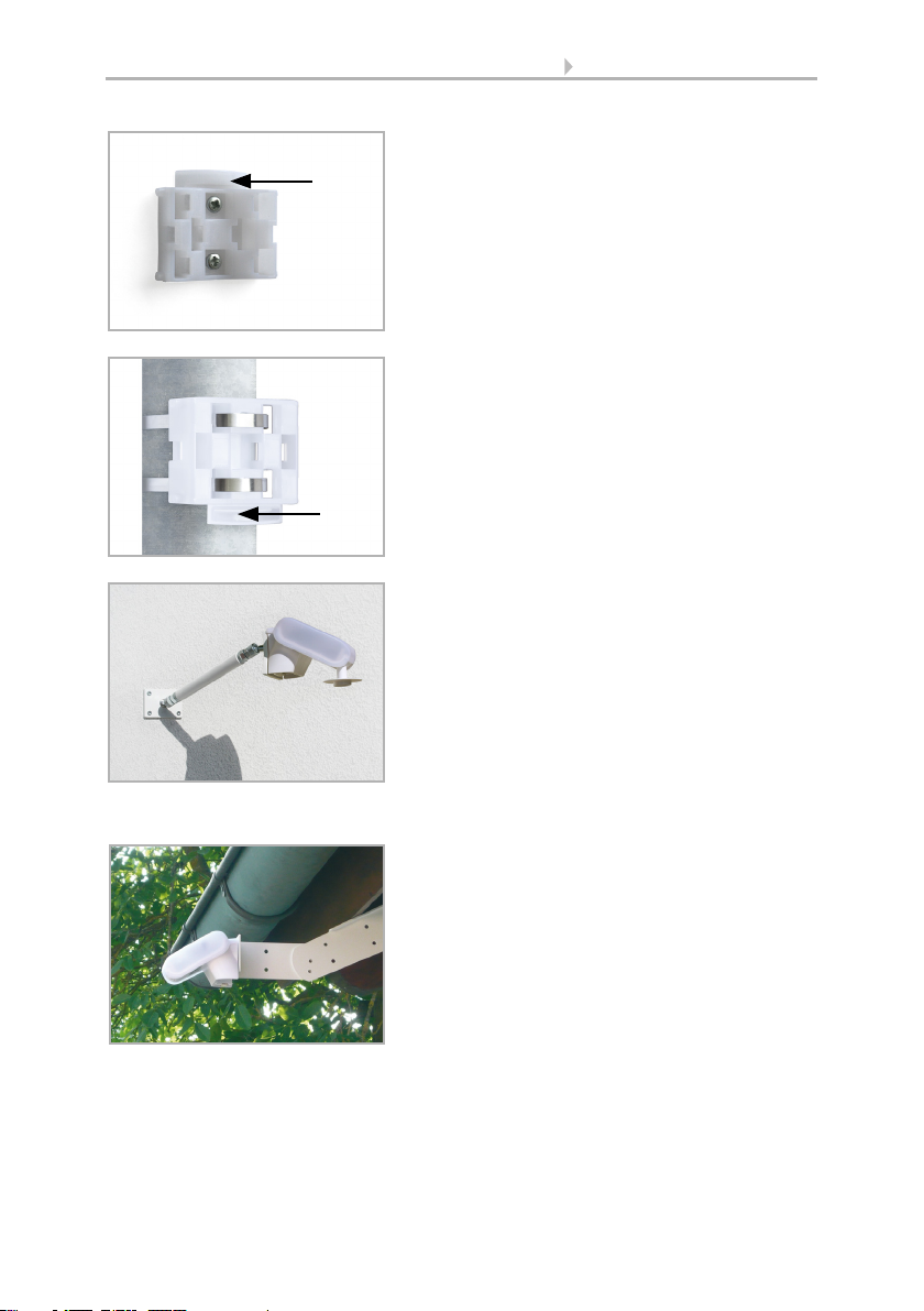
2.2.1. Attaching the mount
The sensor comes with a combination wall/pole mount. The mount comes adhered by
adhesive strips to the rear side of the housing. Fasten the mount vertically onto the wall
or pole.
Fig. 1
There must be at least 60 cm of space below,
to the sides and in front of the sensor left
from other elements (structures, construction
parts, etc.).
60 cm
Fig. 2
The rain/wind sensor must be mounted on a
vertical wall (or a pole).
Wall
or
pole
Fig. 3
The rain/wind sensor must be mounted in the
horizontal transverse direction (horizontally).
Horizontal
6 Installation and commissioning
Rain/Wind Sensor KNX RW • Status: 10.06.2021 • Technical changes reserved. Errors reserved.
Fig. 4
When wall mounting: flat side on wall, crescent-
shaped collar upward.
Collar
Fig. 5
When pole mounting: curved side on pole, collar
downward.
Collar
Fig. 6
Different mounting arms are available from Els-
ner Elektronik as additional, optional accessories
for flexible installation of the weather station on
a wall, pole or beam (pictures of sensors exem-
plary).
Example of the use of a mounting arm: Due to
flexible ball joints, the sensor can be brought
into ideal position.
Fig. 7
Example use of the hinge arm mounting:
With the hinge arm mounting, the weather sta-
tion projects from beneath the roof overhang.
Sun, wind and precipitation can act upon the
sensors without hindrance.

7 Installation and commissioning
Rain/Wind Sensor KNX RW • Status: 10.06.2021 • Technical changes reserved. Errors reserved.
2.2.2. View of rear side and drill hole plan
Fig. 8
Example use of the hinge arm mounting:
Fitting to a pole with worm drive hose clips
Langloch 7,5 x 5 mm
Fig. 9 a+b
Drill hole plan
Dimensions of rear side of housing with bracket.
Subject to change for technical enhancement.

8 Installation and commissioning
Rain/Wind Sensor KNX RW • Status: 10.06.2021 • Technical changes reserved. Errors reserved.
2.2.3. Preparing the sensor
The sensor cover snaps in on the left and right along the bottom edge (see Fig.). The
cover of the 230V model is also screwed on top. Remove the cover. Proceed carefully,
so as not to pull off the wire connecting the PCB in the bottom part with the rain sensor
in the cover (soldered cable connection in case of 230 V AC version, cable with plug in
case of 20...32 V DC version).
Lead the cable for the voltage supply and bus connection through the rubber seals on
the bottom of the device and connect Voltage L/N and Bus +/- to the terminals provid-
ed.
For 20...32 V DC devices the connection cable must be plugged in between the cover
and circuit board.
Fig. 10
1 Screw-on cover (230V
device)
2 Cover with rain sensor
3) Cover Snaps
4 Bottom part of housing
3
4
Unsnap cover and
remove upwards
2
1
Fig. 11
Remove the cable shielding under the circuit
board and only feed the connector cables up-
wards through the openings in the circuit
board.

9 Installation and commissioning
Rain/Wind Sensor KNX RW • Status: 10.06.2021 • Technical changes reserved. Errors reserved.
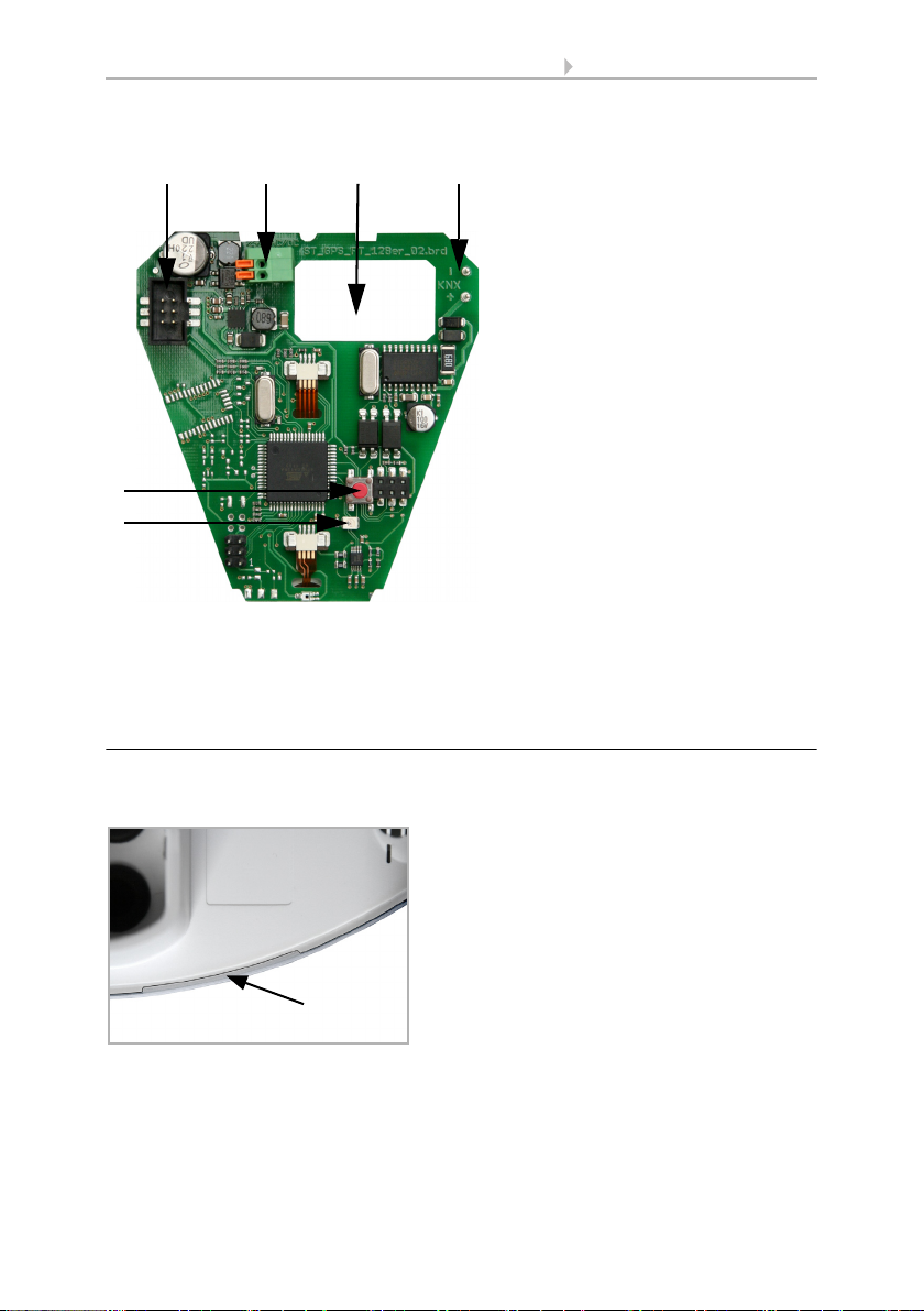
2.2.4. PCB Layout
230 V AC version
Fig. 12
1) Cable connection to the rain
sensor in the housing cover
2) Opening for the cable for the
voltage supply
3) Tension clamp for voltage
supply (230 V AC), suitable for
massive conductors of up to
1.5 mm² or conductors with
fine wires
4) Slot for KNX clamp +/-
5 Opening for the bus cable
6) Programming pushbutton for
the teach-in of the device
7) Programming LED
23
4
6
7
5
1
10 Installation and commissioning
Rain/Wind Sensor KNX RW • Status: 10.06.2021 • Technical changes reserved. Errors reserved.
20...32 V DC version
2.2.5. Mounting the sensor
Close the housing by putting the cover back over the bottom part. The cover must snap
in on the left and right with a definite “click”.
Fig. 13
1 Slot for cable connection to
the rain sensor in the housing
cover
2 Tension clamp for voltage
supply (20...32 V DC).
Massive conductors of up to
1.5 mm² or conductors with
fine wires. Terminal configu-
ration independent from po-
larity (+/- or -/+).
3 Opening for the cable for the
voltage supply and for bus ca-
ble
4SlotforKNXclamp+/-
5 Programming pushbutton for
the teach-in of the device
6 Programming LED
231
5
6
4
Fig. 14
Make sure the cover and bottom part are
properly snapped together! This picture is
looking at the closed sensor from under-
neath.
Fastening
11 Installation and commissioning
Rain/Wind Sensor KNX RW • Status: 10.06.2021 • Technical changes reserved. Errors reserved.
DANGER!
There is a risk to life from the live voltage on a 230 V device!
• The cover must be screwed on in operation.
To remove it, the sensor can be simply pulled upwards out of the mount, against the
resistance of the fastening.
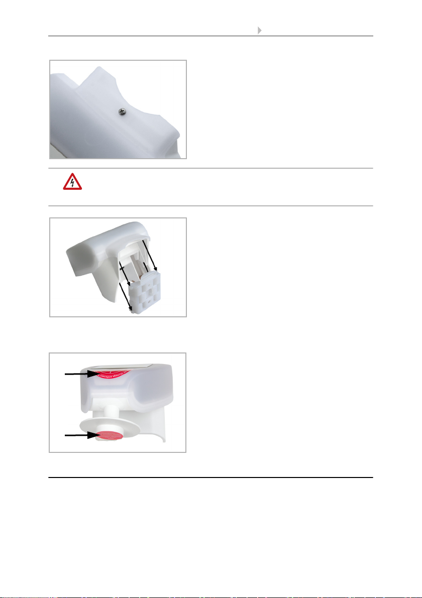
2.3. Notes on mounting and commissioning
Do not open the device if water (rain) might ingress: even some drops might damage
the electronic system.
Observe the correct connections. Incorrect connections may destroy the sensor or con-
nected electronic devices.
Fig. 15
With the 230V model, screw the cover on to
the underpart, to prevent unauthorised or ac-
cidental opening.
Fig. 16
Push the housing from above into the fas-
tened mount. The bumps on the mount must
snap into the rails in the housing.
Fig. 17
After installation, remove the protective sti-
cker on the wind sensor and the "distance"
sticker on the top of the cover.

12 Addressing of the device at the bus
Rain/Wind Sensor KNX RW • Status: 10.06.2021 • Technical changes reserved. Errors reserved.
The measured wind value and thus all other wind switching outputs may only be sup-
plied 60 seconds after the supply voltage has been connected.
After the auxiliary voltage has been applied, the device will enter an initialisation phase
lasting a few seconds. During this phase no information can be received or sent via the
bus.
3. Addressing of the device at the bus
The device is supplied with the bus address 15.15.255. You can program another ad-
dress into the ETS by overwriting the 15.15.255 address or by teaching via the pro-
gramming key on the circuit board inside the housing.
DANGER!
Risk to life from live voltage (mains voltage)!
• With the 230V model, bus addressing via the programming key
should only be done by an accredited electrician.
• Do not touch any components on the circuit board while pressing
the key.
4. Maintenance
DANGER!
There is a risk to life from the live voltage (mains voltage)!
If you come into contact with live components in the device,
(e.g. caused also by a jet of water) there is the risk of an electric
shock with 230 V devices.
Risk of injury caused by components moved automatically!
The automatic control can start system components and place people
in danger (e.g. moving windows/awnings if a rain/wind alarm has
been triggered while cleaning).
• Always isolate the device from the mains for servicing and cleaning
(e. g. switch off or remove the fuse).
The device must regularly be checked for dirt twice a year and cleaned if necessary. In
case of severe dirt, the sensor may not work properly anymore.
ATTENTION
The device can be damaged if water penetrates the housing.
• Do not clean with high pressure cleaners or steam jets.
5. Disposal
After use, the device must be disposed of or recycled in accordance with the legal reg-
ulations. Do not dispose of it with the household waste!

13 Disposal
Rain/Wind Sensor KNX RW • Status: 10.06.2021 • Technical changes reserved. Errors reserved.

14 Transmission protocol
Rain/Wind sensor KNX RW • Status: 10.06.2021 • Technical changes reserved. Errors reserved.
6. Transmission protocol
Units of measurement:
Wind in metre per second
6.1. List of all communication objects
Abbreviations EIS types:
1 Switching1/0
5 Floating point value
6 8 bit value
Abbreviations flags:
C Communication
R Read
WWrite
T Transmit
No Name Function EIS
type
flags
0 Wind force measured value Output 5 C R T
1 Request max. wind force Input 1 C R W
2 Max. wind force measured value Output 5 C R T
3 Reset max. wind force Input 1 C R W
4 Wind threshold value 1 16 bit value 5 C R W T
5 Wind threshold value 1 1 = Increment |
0 = Decrement
1CRW
6 Wind threshold value 1 Increment 1 C R W
7 Wind threshold value 1 Decrement 1 C R W
8 Wind threshold value 1 Switching output 1 C R T
9 Wind threshold value 1 Switching output
block
1CRW
10 Wind threshold value 2 16 bit value 5 C R W T
11 Wind threshold value 2 1 = Increment |
0 = Decrement
1CRW
12 Wind threshold value2 Increment 1 C R W
13 Wind threshold value 2 Decrement 1 C R W
14 Wind threshold value 2 Switching output 1 C R T
15 Wind threshold value 2 Switching output
block
1CRW
16 Wind threshold value 3 16 bit value 5 C R W T
17 Wind threshold value 3 1 = Increment |
0 = Decrement
1CRW
18 Wind threshold value3 Increment 1 C R W

15 Transmission protocol
Rain/Wind sensor KNX RW • Status: 10.06.2021 • Technical changes reserved. Errors reserved.
19 Wind threshold value 3 Decrement 1 C R W
20 Wind threshold value 3 Switching output 1 C R T
21 Wind threshold value 3 Switching output
block
1CRW
22 Wind sensor Disruption Output 1 C R T
23 AND Logic 1 Switching output 1 C R T
24 AND Logic 1 8 bit output A 6 C R T
25 AND Logic 1 8 bit output B 6 C R T
26 AND Logic 2 Switching output 1 C R T
27 AND Logic 2 8 bit output A 6 C R T
28 AND Logic 2 8 bit output B 6 C R T
29 AND Logic 3 Switching output 1 C R T
30 AND Logic 3 8 bit output A 6 C R T
31 AND Logic 3 8 bit output B 6 C R T
32 AND Logic 4 Switching output 1 C R T
33 AND Logic 4 8 bit output A 6 C R T
34 AND Logic 4 8 bit output B 6 C R T
35 AND Logic 5 Switching output 1 C R T
36 AND Logic 5 8 bit output A 6 C R T
37 AND Logic 5 8 bit output B 6 C R T
38 AND Logic 6 Switching output 1 C R T
39 AND Logic 6 8 bit output A 6 C R T
40 AND Logic 6 8 bit output B 6 C R T
41 AND Logic 7 Switching output 1 C R T
42 AND Logic 7 8 bit output A 6 C R T
43 AND Logic 7 8 bit output B 6 C R T
44 AND Logic 8 Switching output 1 C R T
45 AND Logic 8 8 bit output A 6 C R T
46 AND Logic 8 8 bit output B 6 C R T
47 OR Logic 1 Switching output 1 C R T
48 OR Logic 1 8 bit output A 6 C R T
49 OR Logic 1 8 bit output B 6 C R T
50 OR Logic 2 Switching output 1 C R T
51 OR Logic 2 8 bit output A 6 C R T
52 OR Logic 2 8 bit output B 6 C R T
53 OR Logic 3 Switching output 1 C R T
54 OR Logic 3 8 bit output A 6 C R T
55 OR Logic 3 8 bit output B 6 C R T
56 OR Logic 4 Switching output 1 C R T
No Name Function EIS
type
flags

16 Transmission protocol
Rain/Wind sensor KNX RW • Status: 10.06.2021 • Technical changes reserved. Errors reserved.
57 OR Logic 4 8 bit output A 6 C R T
58 OR Logic 4 8 bit output B 6 C R T
59 OR Logic 5 Switching output 1 C R T
60 OR Logic 5 8 bit output A 6 C R T
61 OR Logic 5 8 bit output B 6 C R T
62 OR Logic 6 Switching output 1 C R T
63 OR Logic 6 8 bit output A 6 C R T
64 OR Logic 6 8 bit output B 6 C R T
65 OR Logic 7 Switching output 1 C R T
66 OR Logic 7 8 bit output A 6 C R T
67 OR Logic 7 8 bit output B 6 C R T
68 OR Logic 8 Switching output 1 C R T
69 OR Logic 8 8 bit output A 6 C R T
70 OR Logic 8 8 bit output B 6 C R T
71 Logic input 1 Input 1 C R W
72 Logic input 2 Input 1 C R W
73 Logic input 3 Input 1 C R W
74 Logic input 4 Input 1 C R W
75 Logic input 5 Input 1 C R W
76 Logic input 6 Input 1 C R W
77 Logic input 7 Input 1 C R W
78 Logic input 8 Input 1 C R W
79 Switching output rain Output 1 C R T
80 Software Version readable 6 CR
No Name Function EIS
type
flags

17 Setting of parameters
Rain/Wind sensor KNX RW • Status: 10.06.2021 • Technical changes reserved. Errors reserved.
7. Setting of parameters
7.1. General settings
Wind force
Measured value • do not send
• send cyclically
• send on change
• send on change and cyclically
send cyclically every
(only if sending “cyclically”)
5 sec … 2 h
From change in %
(only if sending “on change“)
1 … 50; 20
Send and reset of the maximum wind load
value on request
do not release • release
Use malfunction object No • Yes
18 Setting of parameters
Rain/Wind sensor KNX RW • Status: 10.06.2021 • Technical changes reserved. Errors reserved.
Rain
7.2. Threshold values
Wind force
7.2.1. Wind threshold value 1 / 2 / 3
Threshold value
If the threshold value is set per Parameter:
If the threshold value is set per Communication object:
From the 1st communication onwards, the threshold value corresponds to the value of
the communication object and is not multiplied by the factor 0.1.
Switching output is with rain 0 • 1
Switching output sends • not
• on change
• on change to 1
• on change to 0
• on change and cyclically
• on change to 1 and cyclically
•on change to 0 and cyclically
send cyclically every
(only if sending “cyclically”)
5 sec … 2 h
Maximum telegram quota 1 • 2 • 3 • 5 • 10 • 20 telegrams per second
Use threshold value 1 / 2 / 3 No • Yes
Transmission delay of the switching
outputs after power up and programming
5 sec … 2 h
Transmission delay of the switching
outputs after power up and programming
5 sec … 2 h
Threshold value setpoint per Parameter • Communication object
Threshold value in 0.1 m/s 0 … 350; 40
Hysteresis of the threshold value in % 0 … 250; 20
The value communicated last shall be
maintained
• not
• after restoration of voltage
(the changes threshold value may be
saved at least 100,000 times)
• after restoration of voltage and
programming (Attention: Do not use
for first commissioning)
This manual suits for next models
2
Table of contents
Other Elsner Accessories manuals

Elsner
Elsner Leak User manual

Elsner
Elsner KNX AQS/TH Guide

Elsner
Elsner KNX VOC-UP basic Guide

Elsner
Elsner KNX T-UP gl Guide

Elsner
Elsner KNX R Guide

Elsner
Elsner KNX L User manual

Elsner
Elsner KNX LW Series User manual

Elsner
Elsner Sewi KNX TH-L-Pr Guide

Elsner
Elsner Vari KNX 3L-TH-D Guide

Elsner
Elsner KNX AQS/TH-B-UP Series Guide


Popular Accessories manuals by other brands


M2M
M2M MCF-LW12VOC manual

IDW
IDW GS-1 instruction manual

ATC Electrical & Mechanical
ATC Electrical & Mechanical atc.ie HANDSU Installation and operation manual

Britax
Britax BOB Gear Deluxe HANDLEBAR CONSOLE WITH PUMP instructions

TREND
TREND T/TFR-4 installation instructions

nedis
nedis KAPC030SS quick start guide