Elsner 71300 Guide

EN
Installation and Adjustment
KNX eTR gl
Temperature Sensor with integra-
ted PI Control
Item numbers 71300 (white), 71302 (black)


1 Contents
Elsner Elektronik GmbH • Sohlengrund 16 • 75395 Ostelsheim • Germany
Temperature Sensor KNX eTR gl • from application 1.0
Version: 07.04.2021 • Technical changes and errors excepted.
1. Safety and operating instructions ....................................................... 3
1.1. Installation notes ...................................................................................................... 3
2. Description ........................................................................................... 3
2.1. Scope of delivery ...................................................................................................... 4
2.2. Technical data ........................................................................................................... 4
2.2.1. Accuracy of the measurement ..................................................................... 5
2.2.2. Device structure ............................................................................................ 5
3. Installation ........................................................................................... 6
3.1. Installation location and preparation ...................................................................... 6
3.2. Mounting ................................................................................................................... 6
4. Notes on mounting and commissioning .............................................. 8
4.1. Addressing of the device at the bus ....................................................................... 8
5. Maintenance and care .......................................................................... 8
6. Disposal ............................................................................................... 8
7. Transmission protocol ......................................................................... 9
7.1. List of all communication objects ........................................................................... 9
8. Setting the parameters ...................................................................... 11
8.1. Behaviour on power failure/ restoration of power .............................................. 11
8.2. General settings ..................................................................................................... 11
8.3. Temperature measured value ............................................................................... 11
8.4. Temperature PI controller ...................................................................................... 12
8.4.1. Heating control stage 1/2 ........................................................................... 17
8.4.2. Cooling control stage 1/2 ........................................................................... 19

2 Clarification of signs
This manual is amended periodically and will be brought into line with new software
releases. The change status (software version and date) can be found in the contents footer.
If you have a device with a later software version, please check
www.elsner-elektronik.de in the menu area "Service" to find out whether a more up-to-
date version of the manual is available.
Clarification of signs used in this manual
Installation, inspection, commissioning and troubleshooting of the device
must only be carried out by a competent electrician.
Safety advice.
Safety advice for working on electrical connections, components,
etc.
DANGER! ... indicates an immediately hazardous situation which will lead to
death or severe injuries if it is not avoided.
WARNING! ... indicates a potentially hazardous situation which may lead to
death or severe injuries if it is not avoided.
CAUTION! ... indicates a potentially hazardous situation which may lead to
trivial or minor injuries if it is not avoided.
ATTENTION! ... indicates a situation which may lead to damage to property if it is
not avoided.
ETS In the ETS tables, the parameter default settings are marked by
underlining.

3 Safety and operating instructions
Temperature Sensor KNX eTR gl • Version: 07.04.2021 • Technical changes and errors excepted.
1. Safety and operating instructions
1.1. Installation notes
Installation, testing, operational start-up and troubleshooting should
only be performed by an authorised electrician.
CAUTION!
Live voltage!
There are unprotected live components inside the device.
• Comply with the locally applicable directives, regulations and provisions
for electrical installation.
• De-energise all cables to be mounted and take safety precautions
against unintentional switch-on.
• Inspect the device for damage before installation. Only put undamaged
devices into operation.
• Immediately take the device or system out of service and secure it
against unintentional switch-on if risk-free operation is no longer guaranteed.
Use the device exclusively for building automation and observe the operating
instructions. Improper use, modifications to the device or failure to observe the
operating instructions will invalidate any warranty or guarantee claims.
Operate the device only as a fixed-site installation, i.e. only in assembled condition and
after conclusion of all installation and operational start-up tasks, and only in the
surroundings designated for it.
Elsner Elektronik is not liable for any changes in norms and standards which may occur
after publication of these operating instructions.
2. Description
The Temperature Sensor KNX eTR gl measures the room temperature. The indoor
sensor can receive an external measured value via the bus and process it with own
data to an overall temperature value (mixed value).
The KNX eTR gl has a integrated PI controller for a heating/cooling system.
Functions:
•Measurement of temperature
•Mixed values from own measured value and external values (proportions can
be set in percentage)
•PI controller for heating (one or two step) and cooling (one or two step)
depending on temperature. Control according to separate target values or
basic target temperature

4 Description
Temperature Sensor KNX eTR gl • Version: 07.04.2021 • Technical changes and errors excepted.
2.1. Scope of delivery
• Temperature Sensor with mounting
• 4 screw anchors 4 × 20 mm, 4 flat head screws 3 × 25 mm
2.2. Technical data
The product conforms with the provisions of EU guidelines.
General:
Casing Genuine glass, plastic
Colours • similar to RAL 9003 signal white
• similar to RAL 9005 deep black
Installation on the wall or on device socket according to DIN 49073
Dimensions housing approx. 81.5 mm x 81.5 mm (W x H),
mounting depth approx. 12 mm
Total weight approx. 70 g
Ambient temperature 0…+55 °C
Ambient humidity 5...95 % RH, non-condensing
Storage temperature -30…+85 °C
Overvoltage category III
Degree of contamination 2
KNX bus:
Medium TP1-256
Configuration mode S-Mode
Group addresses max. 254
Assignments max. 254
Communication objects 41
Nominal voltage 30 V SELV
Power consumption maximum 10 mA
Connection
Conductor diameter
Stripping length
KNX plug terminals
0.6…0.8 mm² s
5mm
Connection
Conductor diameter
Stripping length
Spring-loaded terminals
• rigid and flexible conductors 0.2...0.75 mm²
• flexible conductors with ferrules 0.25...0.34 mm²
7...9 mm
Duration after bus voltage
restoration until data is
received
approx. 5 seconds
Sensor:
Temperature measurement
range
0…+55 °C
Temperature resolution 0.1 °C

5 Description
Temperature Sensor KNX eTR gl • Version: 07.04.2021 • Technical changes and errors excepted.
2.2.1. Accuracy of the measurement
When measuring temperature, the self-heating of the device is considered by the
electronics. The heating is compensated for in the device.
2.2.2. Device structure
2
3Fig. 1
Back view with mounting
2/3 Screw holes for different sockets. Fastening
with 2 screws is sufficient. For wall mounting,
use a fixing material suitable for the ground!
2
22
33
3
Fig. 2
Back view without mounting
4 KNX bus terminal +/- for connection when
mounted on a socket
5 Spring-loaded terminals KNX bus for moun-
ting directly on the wall
6 Programming LED
7 Programming button (recessed) for teaching
device
8 Temperature sensor
PRG key is accessible from below/outside when
the device is mounted (see chapter Addressing
the device).
4 576 8

6 Installation
Temperature Sensor KNX eTR gl • Version: 07.04.2021 • Technical changes and errors excepted.
3. Installation
3.1. Installation location and preparation
The Temperature Sensor KNX eTR gl is made for wall mounting. The device can be
mounted directly on plaster or on device socket according to DIN 49073 and other
sockets, e.g. Swiss device socket.
May be installed and operated in dry interior rooms only.
When selecting an installation location, ensure that the measurement results are
affected as little as possible by external influences. Possible sources of interference
include:
• Direct sunlight
• Drafts from windows and doors
• Draft from ducts which lead from other rooms or from the outside to the
junction box in which the sensor is mounted
• Warming or cooling of the building structure on which the sensor is mounted,
e.g. due to sunlight, heating or cold water pipes
• Connection lines and ducts which lead from warmer or colder areas to the
sensor
Measurement variations from permanent sources of interference can be corrected in
the ETS in order to ensure the specified accuracy of the sensor (offset).
3.2. Mounting
DANGER!
Danger due to electrical voltage
(mains voltage)!
• The socket, in which the device is installed, must not contain cabling
with 230 V.
• Observe the regulations and standards applicable to SELV circuits
during installation and wiring of the KNX connection and inputs.
Prepare the device
Remove the front panel from the mounting. Release the lock by moving the front panel
a few millimetres upwards. The two parts can then be easily separated (Fig. 3).

7 Installation
Temperature Sensor KNX eTR gl • Version: 07.04.2021 • Technical changes and errors excepted.
Screw the mounting onto the wall or socket. The connecting wires (bus line +/-) are led
through the opening in the mounting.
Installation directly on the wall
The wires are pushed into the connection openings.
Installation on a socket
To avoid falsifying the temperature value, use a wind-proof socket and also seal the in-
let pipes against draughts.
Fig. 3 Locking of front panel and mounting
Remove the red-black KNX bus terminal, it is not
required.
Connect the bus +/- connecting wires to the spring-
loaded terminals on the front panel.
Fig. 4 Spring-loaded terminals
To pull it out, press the spring down, e.g. with a
screwdriver.
If there is a cavity behind the device, e.g. when
using a socket, you can use the red/black KNX bus
terminal for connection.

8 Notes on mounting and commissioning
Temperature Sensor KNX eTR gl • Version: 07.04.2021 • Technical changes and errors excepted.
Finish mounting
Snap the front panel into place on the mounting (see Fig. 3): Place it slightly above the
centre position, hook it in and slide it downwards.
The mounting must be installed so that the large opening faces downwards (see Fig.
4). This is necessary for a correct temperature measurement.
4. Notes on mounting and commissioning
Configuration is made using the KNX software as of ETS 5. The product file can be
downloaded from the ETS online catalogue and the Elsner Elektronik website on
www.elsner-elektronik.de in the “Service” menu. There you will also find the
product manual.
After the bus voltage has been applied, the unit will enter an initialisation phase lasting
approx. 5 seconds. During this period, no information can be received or transmitted
via the bus.
4.1. Addressing of the device at the bus
The individual address is assigned via the ETS. A button and a control LED are located
on the unit for this purpose (Fig. 2, No. 6+7).
The programming button is located at the bottom outer side of the front panel of the
device and is recessed. Use a thin object to reach the button, e. g. a 1.5 mm² wire.
The equipment is delivered with the bus address 15.15.255. Another address can be
programmed using the ETS.
5. Maintenance and care
Fingerprints on the glass panel are best removed with a cloth moistened with water or
a microfiber cloth. Do not use an abrasive cleaning agent or aggressive cleansing
agents.
6. Disposal
After use, the device must be disposed of or recycled in accordance with the legal reg-
ulations. Do not dispose of it with the household waste!
PRG
Fig. 5
View from bottom
Temperature sensor

9 Transmission protocol
Temperature Sensor KNX eTR gl • Version: 07.04.2021 • Technical changes and errors excepted
7. Transmission protocol
Units:
Temperatures in degrees Celsius
7.1. List of all communication objects
Abbreviations Flags:
C Communication
R Read
WWrite
T Transmit
UUpdate
No Text Function Flags DPT type Size
0 Software version Output R-CT [217.1] DPT_Ver-
sion
2 Bytes
5 LED brightness in % Input -WC- [5.1] DPT_Scal-
ing
1 Byte
6 Switch LED Input -WC- [1.1] DPT_Switch 1 Bit
7 Temperature sensor: malfunction Output R-CT [1.1] DPT_Switch 1 Bit
8 Temperature sensor: measured
value external
Input -WCT [9.1] DPT_Val-
ue_Temp
2 Bytes
9 Temperature sensor: measured
value
Output R-CT [9.1] DPT_Val-
ue_Temp
2 Bytes
10 Temperature sensor: measured
value total
Output R-CT [9.1] DPT_Val-
ue_Temp
2 Bytes
11 Temperature sensor: measured
value min./max. query
Input -WC- [1.17] DPT_Trig-
ger
1 Bit
12 Temperature sensor: measured
value minimum
Output R-CT [9.1] DPT_Val-
ue_Temp
2 Bytes
13 Temperature sensor: measured
value maximum
Output R-CT [9.1] DPT_Val-
ue_Temp
2 Bytes
14 Temperature sensor: measured
value min./max. reset
Input -WC- [1.17] DPT_Trig-
ger
1 Bit
15 Temp.control: HVAC mode (prior-
ity 1)
Input /
Output
-WC- [20.102] DPT_H-
VACMode
1 Byte
16 Temp.control: HVAC mode (prior-
ity 2)
Input RWCT [20.102] DPT_H-
VACMode
1 Byte
17 Temp.control: Mode frost/heat
protection activt.
Input RWCT [1.1] DPT_Switch 1 Bit
18 Temp.control: Block (1 = Blocking) Input -WC- [1.1] DPT_Switch 1 Bit
19 Temp.control: Current setpoint Output R-CT [9.1] DPT_Val-
ue_Temp
2 Bytes

10 Transmission protocol
Temperature Sensor KNX eTR gl • Version: 07.04.2021 • Technical changes and errors excepted
20 Temp.control: Switch. (0: Heating |
1: Cooling)
Input -WC- [1.1] DPT_Switch 1 Bit
21 Temp.control: Setpoint Comfort
heating
Input /
Output
RWCT [9.1] DPT_Val-
ue_Temp
2 Bytes
22 Temp.control: Setpoint Comfort
heat.(1:+ | 0:-)
Input -WC- [1.1] DPT_Switch 1 Bit
23 Temp.control: Setpoint Comfort
cooling
Input /
Output
RWCT [9.1] DPT_Val-
ue_Temp
2 Bytes
24 Temp.control: Setpoint Comfort
cool.(1:+ | 0:-)
Input -WC- [1.1] DPT_Switch 1 Bit
25 Temp.control: Basic 16-bit setpoint
shift
Input /
Output
RWCT [9.2] DPT_Val-
ue_Tempd
2 Bytes
26 Temp.control: Setpoint Standby
heating
Input /
Output
RWCT [9.1] DPT_Val-
ue_Temp
2 Bytes
27 Temp.control: Setpoint Standby
heat.(1:+ | 0:-)
Input -WC- [1.1] DPT_Switch 1 Bit
28 Temp.control: Setpoint Standby
cooling
Input /
Output
RWCT [9.1] DPT_Val-
ue_Temp
2 Bytes
29 Temp.control: Setpoint Standby
cool. (1:+ | 0:-)
Input /
Output
-WC- [1.1] DPT_Switch 1 Bit
30 Temp.control: Setpoint Eco heat-
ing
Input /
Output
RWCT [9.1] DPT_Val-
ue_Temp
2 Bytes
31 Temp.control: Setpoint Eco heat-
ing (1:+ | 0:-)
Input -WC- [1.1] DPT_Switch 1 Bit
32 Temp.control: Setpoint Eco cool-
ing
Input /
Output
RWCT [9.1] DPT_Val-
ue_Temp
2 Bytes
33 Temp.control: Setpoint Eco cool-
ing (1:+ | 0:-)
Input -WC- [1.1] DPT_Switch 1 Bit
34 Temp.control: Control variable
heating (level 1)
Output R-CT [5.1] DPT_Scal-
ing
1 Byte
35 Temp.control: Control variable
heating (level 2)
Output R-CT [5.1] DPT_Scal-
ing
1 Byte
36 Temp.control: Control variable
cooling (level 1)
Output R-CT [5.1] DPT_Scal-
ing
1 Byte
37 Temp.control: Control variable
cooling (level 2)
Output R-CT [5.1] DPT_Scal-
ing
1 Byte
38 Temperature control: Variable for
4/6-way valve
Output R-CT [5.1] DPT_Scal-
ing
1 Byte
39 Temp.control: Status Heat. level 1
(1=ON|0=OFF)
Output R-CT [1.1] DPT_Switch 1 Bit
40 Temp.control: Status Heat. level 2
(1=ON|0=OFF)
Output R-CT [1.1] DPT_Switch 1 Bit
41 Temp.control: Status Cool. level 1
(1=ON|0=OFF)
Output R-CT [1.1] DPT_Switch 1 Bit
No Text Function Flags DPT type Size

11 Setting the parameters
Temperature Sensor KNX eTR gl • Version: 07.04.2021 • Technical changes and errors excepted
8. Setting the parameters
8.1. Behaviour on power failure/ restoration of
power
Behaviour following a failure of the bus power supply:
The device sends nothing.
Behaviour on bus restoration of power and following programming or reset:
The device sends all outputs according to their send behaviour set in the parameters
with the delays established in the "General settings" parameter block.
8.2. General settings
Set the basic properties of the data transmission.
8.3. Temperature measured value
Select, whether a malfunction object is to be sent if the sensor is faulty.
Use Offsets to adjust the readings to be sent.
42 Temp.control: Status Cool. level 2
(1=ON|0=OFF)
Output R-CT [1.1] DPT_Switch 1 Bit
43 Temp.control: Comfort extension
status
Input /
Output
RWCT [1.1] DPT_Switch 1 Bit
44 Temp.control: Comfort Extension
time
Input RWCT [7.5] DPT_Time-
PeriodSec
2 Bytes
Transmission delay after reset/bus restora-
tion
5s• ... • 7200 s
Maximum message rate • 1 message per second
• ...
• 10 messages per second
• ...
• 50 messages per second
Use malfunction object No • Yes
Offset in 0.1°C -50…50; 0
No Text Function Flags DPT type Size

12 Setting the parameters
Temperature Sensor KNX eTR gl • Version: 07.04.2021 • Technical changes and errors excepted
The unit can calculate a mixed value from its own reading and an external value. Set
the mixed value calculation if desired. If an external portion is used, all of the following
settings (threshold values, etc.) are related to the overall reading.
The minimum and maximum readings can be saved and sent to the bus. Use the
"Reset temperature min/max. value" objects to reset the values to the current readings.
The values are not retained after a reset.
8.4. Temperature PI controller
Activate the controller if you want to use it.
General rules
Decide in which cases nominal values and delay times received per object are to be
kept. The parameter is only taken into consideration if the setting by object is activated
further down. Please note that the setting "After power restoration and programming"
should not be used for the initial start-up, as the factory settings are always used until
the first call (setting via objects is ignored).
For an adequate regulation of the indoor temperature, comfort, standby, eco and build-
ing protection modes may be used.
Comfort when present,
Standby when absent,
Eco as a night-time mode and
Frost / heat protection (building protection) e.g. when the window is open.
The settings for the temperature control include the setpoint temperatures for the in-
dividual modes. Objects are used to determine which mode is to be selected. A change
of mode may be triggered manually or automatically (e.g. by a timer, window contact).
The mode may be switched with two 8 bit objects of different priority. Objects
„... HVAC mode (Prio 2)“ for switching in everyday operation and
„... HVAC mode (Prio 1)“ for central switching with higher priority.
The objects are coded as follows:
0 = Auto
Use external measured value No • Yes
Ext. Reading proportion of the total reading 5% • 10% • ... • 50% • ... • 100%
Sending pattern for internal and total
measured value
• never
• periodically
• on change
• on change and periodically
At and above change of
(if sent on change)
0.1°C • 0.2°C • 0.5°C • ... • 5.0°C
Send cycle
(if sent periodically)
5 s • 10 s • ... • 2 h
Use minimum and maximum value No • Yes
Use controller No • Yes

13 Setting the parameters
Temperature Sensor KNX eTR gl • Version: 07.04.2021 • Technical changes and errors excepted
1 = Comfort
2 = Standby
3 = Eco
4 = Building protection
Alternatively, you can use three objects, with one object switching between eco and
standby mode and the two others are used to activate comfort mode or frost/heat pro-
tection mode. The comfort object then blocks the eco/standby object, and frost/heat
protection objects have the highest priority. Objects
„... Mode (1: Eco, 0: Standby)“,
„... comfort activation mode" and
„... frost/heat protection activation mode"
Select the mode to be activated after reset (e.g. power failure, reset of the line via
the bus). (Default).
Then configure a temperature control block using the blocking object.
Specify when the current control variables are to be sent to the bus. Periodic trans-
mission is safer if a message does not reach a recipient. You may also set up periodical
monitoring by the actuator with this setting.
The status object reports the current status of the output (0 = OFF, 0 = ON) and may
for example be used for visualisation, or to switch off the heating pump as soon as the
heating is switched off.
Switch mode via • two 8-bit objects (HVAC modes)
• three 1-bit objects
Mode after reset • Comfort
• Standby
• Eco
• Building protection
Behaviour of the blocking object with value • 1 = Block | 0 = release
• 0 = block | 1 = release
Value of the blocking object after reset 0 • 1
Send control variable • on change
• on change and periodically
from change of (in % absolute) 1...10; 2
Cycle
(if sent periodically)
5 s • ... • 5 min • … • 2 h
Send status objects • on change
• on change to 1
• on change to 0
• on change and periodically
• on change to 1 and periodically
• on change to 0 and periodically
Cycle
(if sent periodically)
5 s • ... • 5 min • … • 2 h

14 Setting the parameters
Temperature Sensor KNX eTR gl • Version: 07.04.2021 • Technical changes and errors excepted
Then define the type of setting. Heating and/or cooling may be controlled in two
stages.
General setpoint values
You may enter separate setpoint values for each mode or use the comfort setpoint as
a basic value.
If you are using the controls for both heating and cooling, you may also select the set-
ting "separately with switching object". Systems used for cooling in the summer and
for heating in the winter can thus be switched from one to the other.
If you are using the basic value, only the deviation from the comfort setpoint value is
listed for the other modes (e. g., 2°C less for standby mode).
The grades for the setpoint changes is predefined. Whether the change remains active
only temporarily (do not store) or remains stored even after restoration of power (and
programming) is determined in the first section of "General controller". This also ap-
plies to a comfort extension.
The controller can be switched from eco mode, i.e. night mode, to comfort mode via
the comfort extension. This means that the comfort setpoint can be maintained for
longer, for example when having guests. The duration of this comfort extension period
Type of control • Single stage heating
• Dual-stage heating
• Single-stage cooling
• Single-stage heating + single-stage cool-
ing
• Dual-stage heating + single-stage cooling
• Dual-stage heating + dual-stage cooling
Keep modified setpoints after mode
change
No • Yes
Setting the nominal values • separate with switching object
• separate without switching object
• with comfort setpoint as a basis with
switching object
• with comfort setpoint as a basis without
switching object
Analysis of the status object /
Behaviour of the switching object at value
• 0 = Heating | 1 = Cooling
• 1 = Heating | 0 = Cooling
Switching object value
before first Communication
(only if switching object is used)
0• 1
Grading for setpoint changes
(in 0.1 °C)
1… 50; 10
Storage of setpoint(s) • not be retained
• after power restoration
• after restoration of power and program-
ming

15 Setting the parameters
Temperature Sensor KNX eTR gl • Version: 07.04.2021 • Technical changes and errors excepted
is set. After the comfort extension period is terminated, the system returns to eco
mode.
Setpoint Comfort
Comfort mode is usually used for daytime mode when people are present. A starting
value is defined for the comfort setpoint as well as a temperature range in which the
nominal value may be modified.
If setpoint values are entered separately:
If the comfort setpoint value is used as a basis:
If the comfort setpoint is used as the basis, the increase/decrease of this value is indi-
cated.
If the comfort setpoint is used as the basis, a dead zone is determined for the control
mode "heating and cooling" to avoid direct switching from heating to cooling.
Setpoint for standby
Standby mode is usually used for daytime mode when people are absent.
If setpoint values are entered separately:
A starting setpoint value is defined as well as a temperature range in which the setpoint
value may be changed.
Comfort extension time in seconds
(can only be activated from eco mode)
1…36000; 3600
Initial heating/cooling setpoint (in 0.1 °C)
valid until first Communication
(not upon saving the target value after pro-
gramming)
-300…800; 210
Min. object value heating/cooling (in 0.1 °C) -300…800; 160
Max. object value heating/cooling (in 0.1
°C)
-300…800; 280
Minimum base setpoint (in 0.1°C) -300…800; 160
Maximum base setpoint (in 0.1°C) -300…800; 280
Reduction by up to (in 0.1°C) 1…100; 50
Increase by up to (in 0.1°C) 1…100; 50
Dead zone between heating and cooling
(only if both heating AND cooling are used)
1…100; 50
Heating initial setpoint (in 0.1 °C)
valid until first Communication
-300…800; 180
Cooling initial setpoint (in 0.1 °C)
valid until first Communication
-300…800; 240
Min. object value heating/cooling (in 0.1
°C)
-300…800; 160

16 Setting the parameters
Temperature Sensor KNX eTR gl • Version: 07.04.2021 • Technical changes and errors excepted
If the comfort setpoint value is used as a basis:
If the comfort setpoint is used as the basis, the increase/decrease of this value is indi-
cated.
Eco setpoint
Eco mode is usually used for night mode.
If setpoint values are entered separately:
A starting setpoint value is defined as well as a temperature range in which the setpoint
value may be changed.
If the comfort setpoint value is used as a basis:
If the comfort setpoint is used as the basis, the increase/decrease of this value is indi-
cated.
Setpoint values for frost/heat protection (building protection)
The building protection mode is used, for example, as long as windows are open for
ventilation. Setpoints for frost protection (heating) and heat protection (cooling) are
determined which may not be modified from outside (no access via operating devices
etc.). The building protection mode may be activated with delay, which allows you to
leave the building before the controls switch to frost/heat protection mode.
Max. object value heating/cooling (in 0.1
°C)
-300…800; 280
Reduce heating setpoint (in 0.1°C)
(for heating)
0…200; 30
Increase cooling setpoint (in 0.1°C)
(for cooling)
0…200; 30
Heating initial setpoint (in 0.1 °C)
valid until first Communication
-300…800; 160
Cooling initial setpoint (in 0.1 °C)
valid until first Communication
-300…800; 280
Min. object value heating/cooling (in 0.1
°C)
-300…800; 160
Max. object value heating/cooling (in 0.1
°C)
-300…800; 280
Reduce heating setpoint (in 0.1°C)
(for heating)
0…200; 50
Increase cooling setpoint (in 0.1°C)
(for cooling)
0…200; 60
Nominal value frost protection\r\n(in 0,1°C) -300…800; 70
Activation delay no • 5 s • ... • 5 min • … • 2 h
Nominal value heat protection (in 0,1°C) -300…800; 350
Activation delay no • 5 s • ... • 5 min • … • 2 h

17 Setting the parameters
Temperature Sensor KNX eTR gl • Version: 07.04.2021 • Technical changes and errors excepted
General variables
This setting appears for the control types "Heating and Cooling" only. This is where you
can decide whether to use a common variable for heating and cooling. If the 2nd stage
has a common variable, this is also where you determine the control mode of the 2nd
stage.
When using the variable for a 4/6 way valve:
0%...100% Heating = 66%...100% variable
OFF = 50% variable
0%...100% Cooling = 33%...0% variable
8.4.1. Heating control stage 1/2
If a heating control mode is configured, one or two setting sections for the heating
stages are displayed.
In the first stage, heating is controlled by a PI controller which allows to either enter
control parameters or select predetermined applications.
In the second stage (therefore only in case of 2-stage heating), heating is controlled via
a PI or a 2-point-control.
In stage 2, the setpoint deviation between the two stages must also be specified, i.e.
beyond which setpoint undershoot the second stage is then added.
PI controller with control parameters:
This setting allows individual input of the parameters for PI control.
For heating and cooling • separate variables are used
• common variables are used for
Stage 1
• common variables are used for
Stage 2
• common variables are used for
Stage 1+2
Use variable for 4/6-way valve
(only with common variable at stage1)
No • Yes
Control type
(for stage 2 only)
• 2-point-control
• PI control
Regulating variable of the 2nd Stage is on
(only for stage 2 with 2-point control)
• 1-bit object
• 8-bit object
Setpoint difference between stages 1 and 2
stages (in 0.1°C)
(At stage 2)
0...100; 40
Control type
(at stage 2, no common variables)
• 2-point-control
• PI control
Control variable is on
(for stage 2 with 2-point control, no com-
mon variables)
• 1-bit object
• 8-bit object

18 Setting the parameters
Temperature Sensor KNX eTR gl • Version: 07.04.2021 • Technical changes and errors excepted
Specify the deviation from the setpoint value at which the maximum control variable
value is reached, i.e. the point at which maximum heating power is activated.
The reset time shows how quickly the controller responds to deviations from the set-
point. In case of a short reset time, the control responds with a fast increase of the con-
trol variable. In case of a long reset time, the control responds somewhat less urgently
and needs longer until the necessary control variable for the setpoint deviation is
reached.
You should set the time appropriate to the heating system at this point (observe man-
ufacturer's instructions).
Now specify what should be sent when the control is blocked. Set a value greater 0
(=OFF) to receive a basic heating stage, e.g. for floor heating.
On release, the control variable follows the rule again.
In case of a common control variable for heating and cooling, 0 is always transmitted
as a fixed value.
PI control with predetermined application:
This setting provides fixed parameters for frequent applications.
Control type • PI control
Setting of the controller by • Controller parameter
• specified applications
Maximum control variable is reached
at setpoint/actual difference of (in °C)
1...5
Reset time (in min.) 1...255; 30
When blocked, the control variable should • not be sent
• send a specific value
Value (in %)
(only if a value is sent)
0...100
Control type • PI control
Setting of the controller by • Controller parameter
• specified applications
Application • Warm water heating
• Floor heating
• Convection unit
• Electric heating
Maximum control variable is reached
at setpoint/actual difference of (in °C)
Warm water heating: 5
Floor heating: 5
Convection unit: 4
Electric heating: 4
Reset time (in min.) Warm water heating: 150
Floor heating: 240
Convection unit: 90
Electric heating: 100
This manual suits for next models
1
Table of contents
Other Elsner Accessories manuals

Elsner
Elsner Cala KNX AQS/TH Guide
Elsner
Elsner KNX RW Guide
Elsner
Elsner Vari KNX 3L-TH-D Guide
Elsner
Elsner Vari KNX 3L Guide
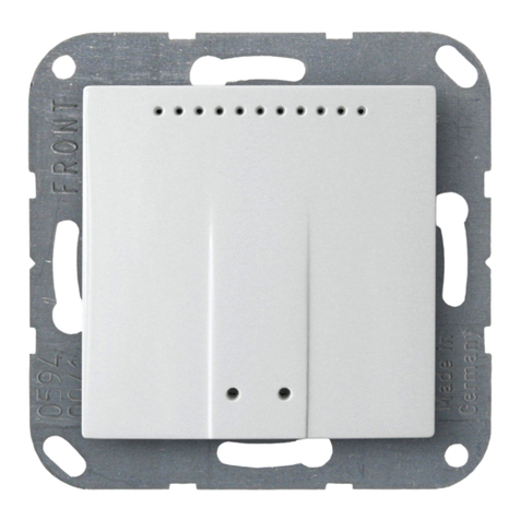
Elsner
Elsner KNX VOC-UP basic Guide
Elsner
Elsner Leak User manual
Elsner
Elsner KNX LW Series User manual
Elsner
Elsner KNX L User manual
Elsner
Elsner KNX R Guide

Elsner
Elsner KNX AQS/TH Guide

