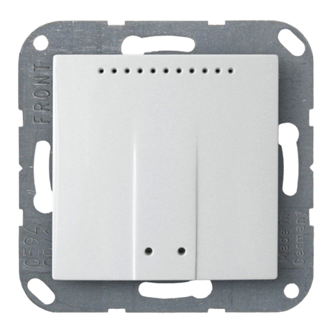
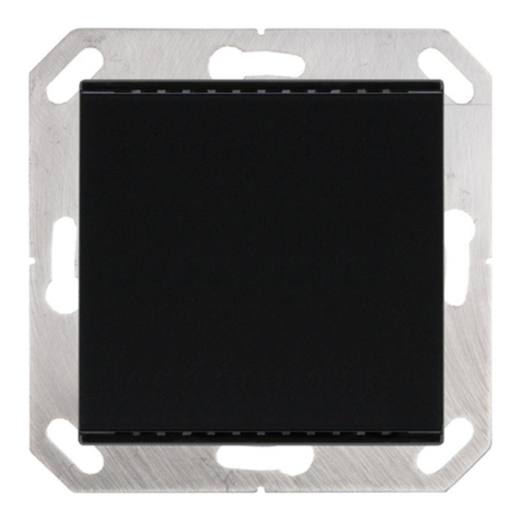
Elsner KNX AQS/TH-B-UP Series Guide

Installation and Adjustment
KNX AQS/TH-B-UP
Combined Indoor Sensor
Elsner Elektronik GmbH Control and AutomationTechnology
Herdweg 7
D – 75391 Gechingen Phone +49 (0) 70 56 / 93 97-0 info@elsner-elektronik.de
Germany Fax +49 (0) 70 56 / 93 97-20 www.elsner-elektronik.de
Item numbers 40239 (white), 40240 (aluminium-coloured), 40241 (anthracite), 40242 (stainless steel coloured)
EN

1 Contents
Elsner Elektronik GmbH • Herdweg 7 • D-75391 Gechingen • Germany
Sensor KNX AQS/TH-B-UP • from software version 0.3.3, ETS programme version 3.1
Status: 24.09.2014 • Subject to technical changes. Errors excepted.
1. Description ........................................................................................... 5
1.0.1. Scope of delivery .......................................................................................... 6
1.1. Technical specifications ........................................................................................... 6
1.1.1. Accuracy of the measurement ..................................................................... 7
2. Installation and commissioning ........................................................... 8
2.1. Installation notes ...................................................................................................... 8
2.2. Installation position .................................................................................................. 8
2.3. Composition ............................................................................................................. 9
2.3.1. Housing .......................................................................................................... 9
2.3.2. Rear view of sensor board with connections ........................................... 10
2.4. Assembly of the sensor ......................................................................................... 10
2.5. Notes on mounting and commissioning .............................................................. 10
3. Display and operation at the device .................................................. 11
3.1. Mode display and manual temperature controller .............................................. 11
3.2. Change ambient temperature with the buttons .................................................. 12
4. Transfer protocol ............................................................................... 14
4.1. List of all communications objects ....................................................................... 14
5. Parameter setting .............................................................................. 23
5.1. Behaviour on power failure/ restoration of power .............................................. 23
5.2. General settings ..................................................................................................... 23
5.3. Measured values: Temperature, humidity, CO2 .................................................. 23
5.4. Threshold values: Temperature, humidity, CO2 .................................................. 24
5.4.1. Threshold value 1, 2, 3, 4: Temperature, humidity, CO2 ......................... 24
Threshold value ........................................................................................... 24
Switching output .......................................................................................... 26
Block .............................................................................................................. 26
5.5. Temperature PI control .......................................................................................... 27
5.5.1. General set point values ............................................................................. 29
Set point Comfort ........................................................................................ 29
Set point for standby ................................................................................... 30
Eco set point ................................................................................................. 30
Set point values for frost/heat protection (building protection) .............. 31
General variables ......................................................................................... 31
5.5.2. Heating control level 1/2 ............................................................................. 31
5.5.3. Cooling control level 1/2 ............................................................................. 34
5.6. Humidity PI control ................................................................................................ 36
General control ............................................................................................ 36
Controller target value ................................................................................. 36
Dehumidification and/or humidification .................................................... 37
5.7. Dewpoint temperature ........................................................................................... 38
5.7.1. Coolant temperature monitoring ............................................................... 39
Minimum coolant temperature threshold value ....................................... 39
Switching output .......................................................................................... 39
Block .............................................................................................................. 40

2 Contents
Elsner Elektronik GmbH • Herdweg 7 • D-75391 Gechingen • Germany
Sensor KNX AQS/TH-B-UP • from software version 0.3.3, ETS programme version 3.1
Status: 24.09.2014 • Subject to technical changes. Errors excepted.
5.8. Absolute humidity .................................................................................................. 40
5.9. Comfort field ........................................................................................................... 41
5.10.CO2 PI control ........................................................................................................ 41
General control ............................................................................................ 42
Controller target value ................................................................................. 42
Ventilation control ....................................................................................... 43
5.11.Variable comparator .............................................................................................. 44
5.11.1. Control variable comparator 1/2 ................................................................ 44
5.12.Logic ........................................................................................................................ 45
AND logic ...................................................................................................... 45
OR logic ........................................................................................................ 45
5.12.1. AND and/or OR logic 1/2/3/4/5/6/7/8 .......................................................... 45
Block .............................................................................................................. 46
5.12.2. AND logic connection inputs ..................................................................... 47
5.12.3. Connection inputs of the OR logic ............................................................. 48
5.13.Display settings ...................................................................................................... 49
5.14.Pushbutton ............................................................................................................. 51
5.14.1. Pushbutton interface 1/2 ............................................................................ 52
5.14.2. Control modes for drive control ................................................................ 54

3 Clarification of signs
This manual is amended periodically and will be brought into line with new software
releases. The change status (software version and date) can be found in the contents footer.
If you have a device with a later software version, please check
www.elsner-elektronik.de in the menu area "Service" to find out whether a more up-to-
date version of the manual is available.
Clarification of signs used in this manual
Installation, inspection, commissioning and troubleshooting of the device
must only be carried out by a competent electrician.
Safety advice.
Safety advice for working on electrical connections, components,
etc.
DANGER! ... indicates an immediately hazardous situation which will lead to
death or severe injuries if it is not avoided.
WARNING! ... indicates a potentially hazardous situation which may lead to
death or severe injuries if it is not avoided.
CAUTION! ... indicates a potentially hazardous situation which may lead to
trivial or minor injuries if it is not avoided.
ATTENTION! ... indicates a situation which may lead to damage to property if it is
not avoided.
ETS In the ETS tables, the parameter default settings are marked by
underlining.

4 Clarification of signs

5 Description
Sensor KNX AQS/TH-B-UP • as of software 3.1 • Status: 24.09.2014 • Technical changes reserved. Errors reserved.
1. Description
The Sensor KNX AQS/TH-B-UP measures CO2concentration, temperature and
humidity and calculates the dew point. The sensor can receive external measured
values via the bus and process them with the own data to overall vealues (mixed
values, e. g. room average). The KNX AQS/TH-B-UP offers two push buttons that may
be used for changing the ambient temperature (target value), for switching between
operating modes or as free programmable bus push buttons.
The KNX AQS/TH-B-UP provides switching outputs with adjustable threshold values.
The switching outputs and further communication objects can be linked by AND and
OR logic gates. Additionally, an integrated actuating variable comparator can compare
and output values that are received via communication objects.
Integrated PI controllers allows for control of a ventilation (depending on CO2
concentration and air humidity) and a heating/cooling system (depending on
temperature). The KNX AQS/TH-B-UP can can emit a warning to the bus as soon as
the area of optimum comfort (according to DIN 1946) is left.
The integrated display shows the own values and data received from the bus (e. g.
date, time). The housing is completed with a frame of the switching series installed in
the building and thus merges with the interior.
Functions:
• Measurement of CO2concentration of the air, of temperature and air
humidity (absolute and relative), calculation of the dew point
•Mixed values from own measured values and external values (proportions
can be set in percentage)
•Display 1-3 rows (own values or values received from the bus) or display of
temperature control (see Mode display and manual temperature controller,
page 11)
•2 push buttons. Configuration as bus push button or for changing ambient
temperature and switching between operating modes (see Change ambient
temperature with the buttons, page 12)
•PI controller for heating (one or two step) and cooling (one or two step)
depending on temperature. Control according to separate target values or
basic target temperature
•PI controller for ventilation depending on humidity and CO2concentration:
dehumidification/humidification (one step) or dehumidification (one or two
step)
•Switching outputs with adjustable threshold values: 3 × temperature, 2 ×
humidity, 4 × CO2. Threshold values can be set by parameter or via
communication objects
•8 AND and 8 OR logic gates with each 4 inputs. Every switching incident as
well as 8 logic inputs in the form of communication objects, may be used as
inputs for the logic gates. The output of each gate may optionally be configured
as 1 bit or 2 x 8 bits

6 Description
Sensor KNX AQS/TH-B-UP • as of software 3.1 • Status: 24.09.2014 • Technical changes reserved. Errors reserved.
•2 actuating variable comparators for output of minimum, maximum or
avarage values. Each with 5 inputs (for values received via communication
objects)
Configuration is made using the KNX software ETS. The product file, the data sheet
and the manual can be downloaded from the Elsner Elektronik homepage on
www.elsner-elektronik.de in the “Service” menu.
1.0.1. Scope of delivery
• Housing with display, buttons and sensor board
•CO
2sensor unit
• Base plate
You will need in addition (not supplied):
• Socket Ø 60 mm, 42 mm deep
• Frame (for element 55 x 55 mm), suitable for the switching programme used in
the building
1.1. Technical specifications
Housing Plastic material (partly lacquered)
Colours • White glossy (similar to RAL 9016 Traffic White)
• Aluminium matt
• Anthracite matt
• Stainless steel
• Special colours on request
Mounting In-wall (in socket Ø60 mm, 42 mm deep)
Protection category IP 20
Dimensions Housing approx. 55 x 55 (W x H, mm),
mounting depth approx. 15 mm,
base plate approx. 71 x 71 (W x H, mm)
Total weight approx. 72 g
Ambient temperature Operation -10…+50°C, storage -20…+60°C
Ambient air humidity max. 95% R. H., avoid bedewing
Operating voltage KNX bus voltage
Bus current max. 10 mA
Data output KNX +/- bus terminal plug
BCU type Own micro controller
PEI type 0
Group addresses max. 254
Allocations max. 254
Communication objects 253
CO2 measurement range 0...2000 ppm
CO2resolution 1 ppm
CO2accuracy* ± 50 ppm ± 3% of the measuered value

7 Description
Sensor KNX AQS/TH-B-UP • as of software 3.1 • Status: 24.09.2014 • Technical changes reserved. Errors reserved.
* Mind the notes on Accuracy of the measurement, page 7
The product conforms with the provisions of EC guidelines
• EMC Directive 2004/108/EC
• Low Voltage Directive 2006/95/EC
The following standards and/or technical specifications have been applied:
• EN 50491-5-1: 2010
• EN 50491-5-2: 2011
• EN 60730-1: 2011
1.1.1. Accuracy of the measurement
Measurement variations from sources of interference (see chapter Installation
position) must be corrected in the ETS in order to ensure the specified accuracy of the
sensor (offset). To ensure a correct CO2measurement, the device must be installed in
a windproof socket.
The indicated accuracy of the CO2measurement will be achieved after a run-in
period of 24 hours (without interruption of the bus voltage) if the sensor has been in
contact with fresh air (350…450 ppm) at least once in this period.
After this, the CO2sensor will recalibrate every two weeks by defining the lowest
measured value captured during that period (without interruption of the bus voltage)
as a reference for fresh air.
The guarantee the accuracy on a sustained basis, the sensor should be provided with
fresh air at least once in two weeks. This occurs normally during room ventilation.
When measuring temperature, the self-heating of the device is considered by the
electronics. The heating is compensated by reducing the measured temperture by the
self-heating of 1.8°C. The indicated indoor temperature measured value approches the
actual room temperature during a 2 hours heating period.
Temperature measurement
range
-30…+60°C
Temperature resolution 0.1°C
Temperature accuracy* ± 0,9°C at 25°C
Humidity measurement
range
0…100%
Humidity resolution 0.1%
Humidity accuracy 0…20 % = ± 5% R. H.
20…80 % = ± 3% R. H.
80…100 % = ± 5% R. H.
Humidity drift ± 0.5% R. H. per year in normal air

8 Installation and commissioning
Sensor KNX AQS/TH-B-UP • as of software 3.1 • Status: 24.09.2014 • Technical changes reserved. Errors reserved.
2. Installation and commissioning
2.1. Installation notes
Installation, testing, operational start-up and troubleshooting should
only be performed by an electrician.
CAUTION!
Live voltage!
There are unprotected live components inside the device.
• National legal regulations are to be followed.
• Ensure that all lines to be assembled are free of voltage and take
precautions against accidental switching on.
• Do not use the device if it is damaged.
• Take the device or system out of service and secure it against
unintentional use, if it can be assumed, that risk-free operation is no
longer guaranteed.
The device is only to be used for its intended purpose. Any improper modification or
failure to follow the operating instructions voids any and all warranty and guarantee
claims.
After unpacking the device, check it immediately for possible mechanical damage. If it
has been damaged in transport, inform the supplier immediately.
The device may only be used as a fixed-site installation; that means only when
assembled and after conclusion of all installation and operational start-up tasks and
only in the surroundings designated for it.
Elsner Elektronik is not liable for any changes in norms and standards which may occur
after publication of these operating instructions.
2.2. Installation position
The Sensor KNX AQS/TH-B-UP will be installed concealed within a socket (Ø 60 mm,
42 mm deep).
May be installed and operated in dry interior rooms only.
Avoid condensation.
For monitoring of the CO2content of the room air choose an installation position in
height of head (standing or sitting, according to utilization of room). The CO2
concentration in indoor rooms is highest near the floor and decreases towards the
ceiling.

9 Installation and commissioning
Sensor KNX AQS/TH-B-UP • as of software 3.1 • Status: 24.09.2014 • Technical changes reserved. Errors reserved.
When selecting an installation location, please ensure that the measurement results
are affected as little as possible by external influences. Possible sources of interference
include:
• Direct sunlight
• Drafts from windows and doors
• Draft from ducts which lead from other rooms or from the outside to the
junction box in which the sensor is mounted
• Warming or cooling of the building structure on which the sensor is mounted,
e.g. due to sunlight, heating or cold water pipes
• Connection lines and ducts which lead from warmer or colder areas to the
sensor
Measurement variations from such sources of interference must be corrected in the
ETS in order to ensure the specified accuracy of the sensor (offset).
To ensure a correct CO2measurement, the device must be installed in a windproof
socket.
2.3. Composition
2.3.1. Housing
Fig. 1
1 Base plate
2 Catches
3 Openings for air circulation
4 Push button
5 Programming LED (recessed)
6 Programming button
(recessed) for teaching device
7 Push button
8 Openings for air circulation
(LOWER)
3
24
6
7
5
8
1

10 Installation and commissioning
Sensor KNX AQS/TH-B-UP • as of software 3.1 • Status: 24.09.2014 • Technical changes reserved. Errors reserved.
2.3.2. Rear view of sensor board with connections
2.4. Assembly of the sensor
First of all fit the windproof socket with connection. Also seal inlet pipes to avoid
infiltration.
Screw the base plate onto the socket and position the frame of the switching
programme. Connect the CO2sensor unit and the bus line +/- (black-red plug) to the
terminals provided on the board.
Pin the sensor with the notches on to the metal frame, so that sensor and frame are
fixed.
2.5. Notes on mounting and commissioning
Never expose the device to water (e.g. rain) or dust. This can damage the electronics.
You must not exceed a relative humidity of 95%. Avoid condensation.
After the bus voltage has been applied, the device will enter an initialisation phase
lasting a few seconds. During this phase no information can be received via the bus.
Fig. 2
1 KNX terminal BUS +/-
2Notches
3SlotforCO
2sensor unit
4 Plug of CO2 sensor unit
5CO
2sensor unit
Lenght of cable approx. 110 mm
a Hole centre distance approx. 43 mm
b Diameter of diaphragm
approx. 18 mm
2
1
34 5
a
b
Place the CO2sensor unit in the socket. The side with the sensor
membrane must face to front.
Fig. 3

11 Display and operation at the device
Sensor KNX AQS/TH-B-UP • as of software 3.1 • Status: 24.09.2014 • Technical changes reserved. Errors reserved.
3. Display and operation at the device
Specifications for the display are set in the ETS and the use of the push buttons is
permitted or disabled.
Basically the display can show a two-row or three-row text (e. g. for measured values)
or a tempertuare controller. You can switch between the two types by pressing one of
the buttons, if this has not been disabled in the ETS.
3.1. Mode display and manual temperature
controller
Depending on the ETS setting selected, the mode display will only display show the
current target value, or the base target value setting with scale display. The manually
adjustable range can be set in the ETS.
The following display options are available:
Fig. 4
Mode display with current target value and/or base
target value
Fig. 5
Mode display with scale display for adjusting the base
target value.
The control position in the image reads "Base target
value reduced".
Fig. 6
Mode display with scale display and number.
Shows the set target value change.
The control position in the image reads "Base target
value reduced to 1.0°".
Fig. 7
Mode display with scale display and range.
Shows the possible adjustment range (as set in the ETS).
The control position in the image reads "Base target
value reduced".

12 Display and operation at the device
Sensor KNX AQS/TH-B-UP • as of software 3.1 • Status: 24.09.2014 • Technical changes reserved. Errors reserved.
Symbols
Priority (points)
One point: Priority 1/priority control. It is not possible to adjust the temperature
automation system manually. Neither the target temperature nor the operating modes
can be changed using the buttons on the unit.
Two points: Priority 2. The target temperature and operating mode can be changed
using the buttons.
3.2. Change ambient temperature with the
buttons
If the mode display is active, the target ambient temperature and the operating mode
can be changed manually using the buttons. The button functions can be blocked in
the ETS or be suppressed for Priority 1 operating modes. The individual operating
modes can also be locked for manual selection in the ETS.
Comfort mode.
Comfort (present) target
temperature will be used.
Standby mode.
Standby (absent during day)
target temperature will be used.
Eco mode.
Night target temperature will be
used.
Building protection mode.
Building protection target
temperature will be used. The
symbol will blink when the
mode has been activated but the
activation delay has not yet
expired.
Heating mode.
Heating will be provided.
Cooling mode
Cooling will be provided.
Fig. 8
Mode display with scale display, range and number.
Displays the possible adjustment range (as set in the
ETS) and the set target value change.
The control position in the image reads "Base target
value reduced to 1.0°".
Fig. 9
In "HVAC mode with 2x 8 bits" control mode, points are
shown under the symbol, to indicate the running priority
of the current mode.

13 Display and operation at the device
Sensor KNX AQS/TH-B-UP • as of software 3.1 • Status: 24.09.2014 • Technical changes reserved. Errors reserved.
Decrease target
temperature (-)
briefly press
left button
Ambient temperature in the current
mode is decreased.
The sep-size is defined in the ETS
(0.1°C to 5°C).
Increase target
temperature (+)
briefly press
right button
Ambient temperature in the current
mode is increased.
The sep-size is defined in the ETS
(0.1°C to 5°C).
Change mode press
left or right button
longer than 2 secs.
Changes between the operating
modes Comfort, Standby, Eco and
Building Protection (if deblocked in
the ETS).
Extend Comfort
mode
in Eco mode:
press both buttons
at the same time
longer than 2 secs.
Switches from Eco to Comfort mode
again for a certain time (e. g. if the
rooms are used longer in the
evening).
The period is defined in the ETS (up
to 10 hours). The time remaining in
Comfort mode is displayed.

14 Transfer protocol
Sensor KNX AQS/TH-B-UP • as of software 3.1 • Status: 24.09.2014 • Technical changes reserved. Errors reserved.
4. Transfer protocol
Units:
Temperatures in degrees Celsius
Air humidity in %
Absolute air humidity in g/kg and/or g/m3
CO2content in ppm
Variables in %
4.1. List of all communications objects
Abbreviation flags:
C Communication
R Read
WWrite
T Transfer
UUpdate
No. Name Function DPT Flags
0 Software version readable 217,001 C R T
1 Temperature/humidity malfunction
sensor
Output 1,001 C R T
2 CO2 sensor malfunction Output 1,001 C R T
3 Outside temperature reading Input 9,001 C W
4 Inside temperature reading Output 9,001 C R T
5 Overall temperature reading Output 9,001 C R T
6 Min./max. temperature value request Input 1,017 C W
7 Minimum temperature reading Output 9,001 C R T
8 Maximum temperature reading Output 9,001 C R T
9 Reset min./max. temperature value Input 1,017 C W
10 Temp. threshold value 1: Absolute
value
Input/Output 9,001 C R W T
U
11 Temp. threshold value 1: (1:+ | 0:-) Input 1,002 C W
12 Temp. threshold value 1:
Switching delay from 0 to 1
Input 7,005 C W
13 Temp. threshold value 1:
Switching delay from 1 to 0
Input 7,005 C W
14 Temp. threshold value 1: Switching
output
Output 1,001 C R T
15 Temp. threshold value 1:
Switching output block
Input 1,002 C W

15 Transfer protocol
Sensor KNX AQS/TH-B-UP • as of software 3.1 • Status: 24.09.2014 • Technical changes reserved. Errors reserved.
16 Temp. threshold value 2: Absolute
value
Input/Output 9,001 C R W T
U
17 Temp. threshold value 2: (1:+ | 0:-) Input 1,002 C W
18 Temp. threshold value 2:
Switching delay from 0 to 1
Input 7,005 C W
19 Temp. threshold value 2:
Switching delay from 1 to 0
Input 7,005 C W
20 Temp. threshold value 2: Switching
output
Output 1,001 C R T
21 Temp. threshold value 2:
Switching output block
Input 1,002 C W
22 Temp. threshold value 3: Absolute
value
Input/Output 9,001 C R W T
U
23 Temp. threshold value 3: (1:+ | 0:-) Input 1,002 C W
24 Temp. threshold value 3:
Switching delay from 0 to 1
Input 7,005 C W
25 Temp. threshold value 3:
Switching delay from 1 to 0
Input 7,005 C W
26 Temp. threshold value 3: Switching
output
Output 1,001 C R T
27 Temp. threshold value 3:
Switching output block
Input 1,002 C W
28 Reserve
29 TR_1_ Eco-Standby HVAC 1 Input 1,003 C W
30 TR_1_ Comfort Activation HVAC 2 Input 1,003 C W
31 TR_1_ Frost/Heat activation Input 1,003 C R W T
32 TR_1_ Blocking object Input 1,003 C W
33 TR_1_ Target value, current Output 9,001 C R T
34 TR_1_ Switching object (0:Heat |
1:Cool)
Input 1,002 C W
35 TR_1_ Target value, comfort heating Input/Output 9,001 C R W T
36 TR_1_ Target value, comfort heating
(1:+ | 0:-)
Input 1,002 C W
37 TR_1_ Target value, comfort cooling Input/Output 9,001 C R W T
38 TR_1_ Target value, comfort cooling
(1:+ | 0:-)
Input 1,002 C W
39 TR_1_ Target value_Basic offset Input/Output 9,001 C R W T
40 TR_1_ Target value, Standby heating Input/Output 9,001 C R W T
41 TR_1_ Target value, Standby heating
(1:+ | 0:-)
Input 1,002 C W
42 TR_1_ Target value, Standby cooling Input/Output 9,001 C R W T
No. Name Function DPT Flags

16 Transfer protocol
Sensor KNX AQS/TH-B-UP • as of software 3.1 • Status: 24.09.2014 • Technical changes reserved. Errors reserved.
43 TR_1_ Target value, Standby cooling
(1:+ | 0:-)
Input 1,002 C W
44 TR_1_ Target value, Eco heating Input/Output 9,001 C R W T
45 TR_1_ Target value, Eco heating (1:+ |
0:-)
Input 1,002 C W
46 TR_1_ Target value, Eco cooling Input/Output 9,001 C R W T
47 TR_1_ Target value, Eco cooling (1:+ |
0:-)
Input 1,002 C W
48 TR_1_ Control variable heating (stage
1)
Output 5,001 C R T
49 TR_1_ Control variable heating stage
2
Output 5,001 C R T
50 TR_1_ Control variable cooling (stage
1)
Output 5,001 C R T
51 TR_1_ Control variable cooling stage
2
Output 5,001 C R T
52 TR_1_ Status heating 1 (1=ON |
0=OFF)
Output 1,002 C R T
53 TR_1_ Status heating 2 (1=ON |
0=OFF)
Output 1,002 C R T
54 TR_1_ Cooling status 1 (1=ON |
0=OFF)
Output 1,002 C R T
55 TR_1_ Cooling status 2 (1=ON |
0=OFF)
Output 1,002 C R T
56 TR_1_ Comfort Delay Status Input/Output 1,002 C R W T
57 TR_1_Comfort extension time (in sec) Input/Output 7,005 C R W T
58 TR_1_Belimo_Control variable Output 5,001 C R T
59 Outside humidity reading Input 9,007 C W
60 Inside humidity reading Output 9,007 C R T
61 Overall humidity reading Output 9,007 C R T
62 Min./max. humidity value request Input 1,017 C W
63 Minimum humidity reading Output 9,007 C R T
64 Maximum humidity reading Output 9,007 C R T
65 Reset min./max. humidity value Input 1,017 C W
66 Humidity threshold value 1: Absolute
value
Input/Output 9,007 C R W T
U
67 Humidity threshold value 1: (1:+ | 0:-) Input 1,002 C W
68 Humidity threshold value 1: Switch-
ing delay from 0 to 1
Input 7,005 C W
69 Humidity threshold value 1: Switch-
ing delay from 1 to 0
Input 7,005 C W
No. Name Function DPT Flags

17 Transfer protocol
Sensor KNX AQS/TH-B-UP • as of software 3.1 • Status: 24.09.2014 • Technical changes reserved. Errors reserved.
70 Humidity threshold value 1: Switch-
ing output
Output 1,001 C R T
71 Humidity threshold value 1: Switch-
ing output block
Input 1,002 C W
72 Humidity threshold value 2: Absolute
value
Input/Output 9,007 C R W T
U
73 Humidity threshold value 2: (1:+ | 0:-) Input 1,002 C W
74 Humidity threshold value 2: Switch-
ing delay from 0 to 1
Input 7,005 C W
75 Humidity threshold value 2: Switch-
ing delay from 1 to 0
Input 7,005 C W
76 Humidity threshold value 2: Switch-
ing output
Output 1,001 C R T
77 Humidity threshold value 2: Switch-
ing output block
Input 1,002 C W
78 Humidity controller: Blocking object Input 1,002 C W
79 Humidity controller: Target value Input/Output 9,007 C R W T
80 Humidity controller: Target value (1:+
| 0:-)
Input 1,002 C W
81 Humidity controller: Control variable
dehumidification (stage 1)
Output 5,001 C R T
82 Humidity controller: Control variable
dehumidification stage 2
Output 5,001 C R T
83 Humidity controller: Control variable
humidification
Output 5,001 C R T
84 Humidity controller: Dehumidification
1 status (1=ON | 0=OFF)
Output 1,001 C R T
85 Humidity controller: Dehumidification
2 status (1=ON | 0=OFF)
Output 1,001 C R T
86 Humidity controller: Humidification
status (1=ON | 0=OFF)
Output 1,001 C R T
87 Dewpoint temperature Output 9,001 C R T
88 Coolant temp.: Threshold value Output 9,001 C R T
89 Coolant temp.: Actual value Input 9,001 C W
90 Coolant temp.: Offset change (1:+ | 0:-
)
Input 1,002 C W
91 Coolant temp.: Switching delay from
0 to 1
Input 7,005 C W
92 Coolant temp.: Switching delay from
1 to 0
Input 7,005 C W
93 Coolant temp.: Switching output Output 1,001 C R T
No. Name Function DPT Flags

18 Transfer protocol
Sensor KNX AQS/TH-B-UP • as of software 3.1 • Status: 24.09.2014 • Technical changes reserved. Errors reserved.
94 Coolant temp.: Switching output
block
Input 1,002 C W
95 Absolute humidity [g/kg] Output 14,005 C R T
96 Absolute humidity [g/m³] Output 14,017 C R T
97 Ambient climate status: 1 = comforta-
ble | 0 = uncomfortable
Output 1,002 C R T
98 Outside CO2 reading Input 9,008 C W
99 Inside CO2 Internal reading Output 9,008 C R T
100 Total CO2 reading Output 9,008 C R T
101 CO2 maximum value request Input 1,017 C W
102 Maximum CO2 reading Output 9,008 C R T
103 Reset CO2 maximum value Input 1,017 C W
104 CO2 threshold value 1: Absolute
value
Input/Output 9,008 C R W T
U
105 CO2 threshold value 1: (1:+ | 0:-) Input 1,002 C W
106 CO2 threshold value 1: Switching
delay from 0 to 1
Input 7,005 C W
107 CO2 threshold value 1: Switching
delay from 1 to 0
Input 7,005 C W
108 CO2 threshold value 1: Switching out-
put
Output 1,001 C R T
109 CO2 threshold value 1: Switching out-
put block
Input 1,002 C W
110 CO2 threshold value 2: Absolute
value
Input/Output 9,008 C R W T
U
111 CO2 threshold value 2: (1:+ | 0:-) Input 1,002 C W
112 CO2 threshold value 2: Switching
delay from 0 to 1
Input 7,005 C W
113 CO2 threshold value 2: Switching
delay from 1 to 0
Input 7,005 C W
114 CO2 threshold value 2: Switching out-
put
Output 1,001 C R T
115 CO2 threshold value 2: Switching out-
put block
Input 1,002 C W
116 CO2 threshold value 3: Absolute
value
Input/Output 9,008 C R W T
U
117 CO2 threshold value 3: (1:+ | 0:-) Input 1,002 C W
118 CO2 threshold value 3: Switching
delay from 0 to 1
Input 7,005 C W
119 CO2 threshold value 3: Switching
delay from 1 to 0
Input 7,005 C W
No. Name Function DPT Flags

19 Transfer protocol
Sensor KNX AQS/TH-B-UP • as of software 3.1 • Status: 24.09.2014 • Technical changes reserved. Errors reserved.
120 CO2 threshold value 3: Switching out-
put
Output 1,001 C R T
121 CO2 threshold value 3: Switching out-
put block
Input 1,002 C W
122 CO2 threshold value 4: Absolute
value
Input/Output 9,008 C R W T
U
123 CO2 threshold value 4: (1:+ | 0:-) Input 1,002 C W
124 CO2 threshold value 4: Switching
delay from 0 to 1
Input 7,005 C W
125 CO2 threshold value 4: Switching
delay from 1 to 0
Input 7,005 C W
126 CO2 threshold value 4: Switching out-
put
Output 1,001 C R T
127 CO2 threshold value 4: Switching out-
put block
Input 1,002 C W
128 CO2 controller: Blocking object Input 1,002 C W
129 CO2 controller: Target value Input/Output 9,008 C R W T
130 CO2 controller: Target value (1:+ | 0:-) Input 1,002 C W
131 CO2 controller: Control variable venti-
lation (stage 1)
Output 5,001 C R T
132 CO2 controller: Control variable venti-
lation (stage 2)
Output 5,001 C R T
133 CO2 controller: Ventilation 1 status
(1=ON | 0=OFF)
Output 1,001 C R T
134 CO2 controller: Ventilation 2 status
(1=ON | 0=OFF)
Output 1,001 C R T
135 Comparator 1 actuating variable:
Input 1
Input 5,010 C W
136 Comparator 1 actuating variable:
Input 2
Input 5,010 C W
137 Comparator 1 actuating variable:
Input 3
Input 5,010 C W
138 Comparator 1 actuating variable:
Input 4
Input 5,010 C W
139 Comparator 1 actuating variable:
Input 5
Input 5,010 C W
140 Comparator 1 actuating variable: Out-
put
Output 1,001 C R T
141 Comparator 1 actuating variable:
Block
Input 1,002 C W
142 Comparator 2 actuating variable:
Input 1
Input 5,010 C W
No. Name Function DPT Flags
This manual suits for next models
4
Table of contents
Other Elsner Accessories manuals
Elsner
Elsner KNX T-UP gl Guide

Elsner
Elsner KNX AQS/TH Guide

Elsner
Elsner 71300 Guide

Elsner
Elsner Sewi KNX TH-L-Pr Guide
Elsner
Elsner Vari KNX 3L-TH-D Guide
Elsner
Elsner KNX RW Guide
Elsner
Elsner Vari KNX 3L Guide
Elsner
Elsner KNX L User manual
Elsner
Elsner Cala KNX AQS/TH Guide
Elsner
Elsner KNX LW Series User manual
Popular Accessories manuals by other brands
Wirebus
Wirebus WCS-300 user manual
Honeywell
Honeywell Notifier NFSTI-SMT2 Installation and maintenance instructions
XDream
XDream X-Cell Plus quick start guide

LEGRAND
LEGRAND Wattstopper FSP-301 installation instructions
Panasonic
Panasonic MA4SD01 Specification sheet
Wavetronix
Wavetronix Click 510 quick start guide
