Elsner KNX R Guide

KNX R
Rain Sensor
Installation and Adjustment

Product description...........................................................................................2
Technical specifications................................................................................................2
PCB layout ....................................................................................................................3
230 V AC version.................................................................................................................................. 3
24 V DC version.................................................................................................................................... 4
Installation and commissioning ........................................................................4
Location ........................................................................................................................5
Attaching the mount............................................................................................................................ 5
View of rear side and drill hole plan .................................................................................................. 7
Preparing the sensor ........................................................................................................................... 8
Mounting the sensor ........................................................................................................................... 8
Notes on installation............................................................................................................................ 9
Maintenance..................................................................................................................9
Transmission protocol..................................................................................... 10
Abbreviations..................................................................................................................................... 10
Listing of all communication objects..........................................................................10
Setting of parameters .....................................................................................12
General settings ..........................................................................................................12
Logic ...........................................................................................................................13
AND Logic 1 / 2 / 3 / 4 ........................................................................................................................ 14
Linkage inputs of AND logic ............................................................................................................. 17
OR Logic 1 / 2 / 3 / 4 ........................................................................................................................... 17
Linkage inputs of OR logic ................................................................................................................ 19
KNX R Rain Sensor • from software version 1.00, ETS programme version 1.1 • Status:
01.07.2009. Errors excepted. Subject to technical changes
Elsner Elektronik GmbH Steuerungs- und Automatisierungstechnik
Herdweg 7 • D-75391 Gechingen • Germany
Phone: +49 (0) 70 56/93 97-0 • Fax: +49 (0) 70 56/93 97-20

2
Product description
The rain sensor registers precipitation and transfers the status to the KNX system. One
switching output as well as AND and OR logic gates are available.
The sensor system, the evaluation electronics and the electronics of the bus connection
are mounted in a compact housing.
Functions:
•Precipitation perception: The surface of the sensor is heated so that only drops
and flakes are recognised as precipitation but not fog or dew. If it stops raining or
snowing, the sensor dries quickly and the precipitation message ends
•1 switching output
•4 AND and 4 OR logic gates with each 4 inputs. Every switching incident as well
as 8 logic inputs (in the form of communication objects) may be used as inputs for
the logic gates. The output of each gate may optionally be configured as 1 bit or 2 x
8 bits
Configuration is made using the KNX software ETS. The programme file (format VD2)
can be downloaded from the Elsner Elektronik homepage on www.elsner-
elektronik.de in the “Service” menu.
Technical specifications
Housing: Plastic material
Colour: White / translucent
Mounting: On-wall
Protection category: IP 44
Dimensions: approx. 96 × 77 × 118 (W × H × D, mm)
Weight: 230 V AC version: approx. 240 g
24 V DC version: approx. 170 g
Ambient temperature: Operation -30…+50°C, Storage -30…+70°C
Operating voltage: Available for 230 V AC or for 24 V DC (20 V AC)
Current: 230 V AC version: max. 20 mA
24 V DC version: max. 100 mA
Residual ripple 10%
Data output: KNX +/- bus terminal plug
BCU type: Own micro controller
PEI type: 0
Group addresses: max. 254
Allocations: max. 255
Communication objects: 34
Heating rain sensor: approx. 1.2 W (230 V and 24 V)
3
The following standards have been considered for the evaluation of the product in
terms of electro magnetic compatibility:
Transient emissions:
•EN 60730-1:2000 Section EMV (23, 26, H23, H26) (threshold category: B)
•EN 50090-2-2:1996-11 + A1:2002-01 (threshold category: B)
•EN 61000-6-3:2001 (threshold category: B)
Interference resistance:
•EN 60730-1:2000 Section EMV (23, 26, H23, H26)
•EN 50090-2-2:1996-11 + A1:2002-01
•EN 61000-6-1:2004
The product has been tested for the above mentioned standards by an accredited EMV
laboratory.
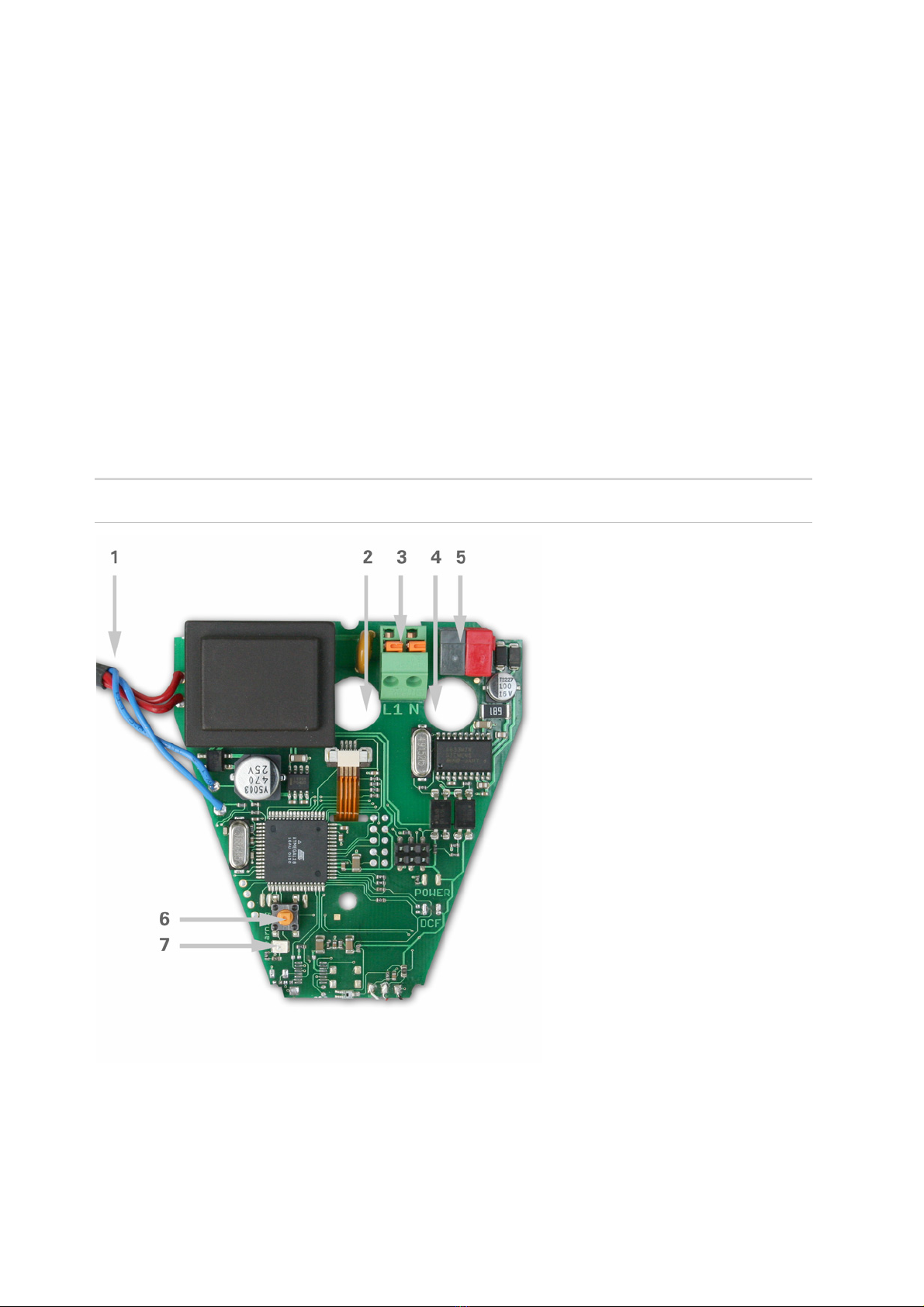
PCB layout
230 V AC version
Fig. 1
1 Cable connection to the rain
sensor in the housing cover
2 Opening for the cable for the
voltage supply
3 Tension clamp for voltage
supply (230 V AC), suitable for
massive conductors of up to
1.5 mm² or conductors with
fine wires
4 Opening for bus cable
5 KNX clamp +/-
6 Programming pushbutton for
the teach-in of the device
7 Programming LED

4
24 V DC version
Fig. 2
1 Slot for cable connection to the
rain sensor in the housing cover
2 Tension clamp for voltage
supply (24 V DC/20 V AC), suitable
for massive conductors of up to
1.5 mm² or conductors with fine
wires
3 Opening for the cable for the
voltage supply
4 Opening for bus cable
5 KNX clamp +/-
6 Programming pushbutton for
the teach-in of the device
7 Programming LED
Installation and commissioning
Attention! Mains voltage!
The legal national regulations must be complied with.
Installation, inspection, commissioning and troubleshooting of the rain sensor must
only be carried out by a competent electrician. Disconnect all lines to be assembled, and
take safety precautions against accidental switch-on.
The rain sensor is exclusively intended for appropriate use. With each inappropriate
change or non-observance of the instructions for use, any warranty or guarantee claim
will be void.
After unpacking the device, check immediately for any mechanical damages. In case of
transport damage, this must immediately notified to the supplier.
If damaged, the rain sensor must not
be put into operation.
5
If an operation without risk may supposedly not be guaranteed, the device must be put
out of operation and be secured against accidental operation.
The rain sensor must only be operated as stationary system, i.e. only in a fitted state
and after completion of all installation and start-up works, and only in the environment
intended for this purpose.
Elsner Elektronik does not assume any liability for changes in standards after
publication of this instruction manual.
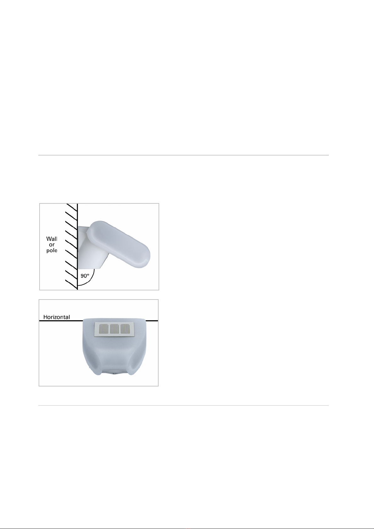
Location
Select an assembly location at the building where precipitation may be collected by the
sensor unobstructedly. Do not assemble any construction components above the
sensor from where water may drop on to the rain sensor after it has stopped raining or
snowing.
Fig. 3: The rain sensor must be mounted onto a
vertical wall (or pole).
Fig.4: The rain sensor must be mounted
horizontally in the lateral direction.
Attaching the mount
The rain sensor comes with a combination wall/pole mount. The mount comes adhered
by adhesive strips to the rear side of the housing.
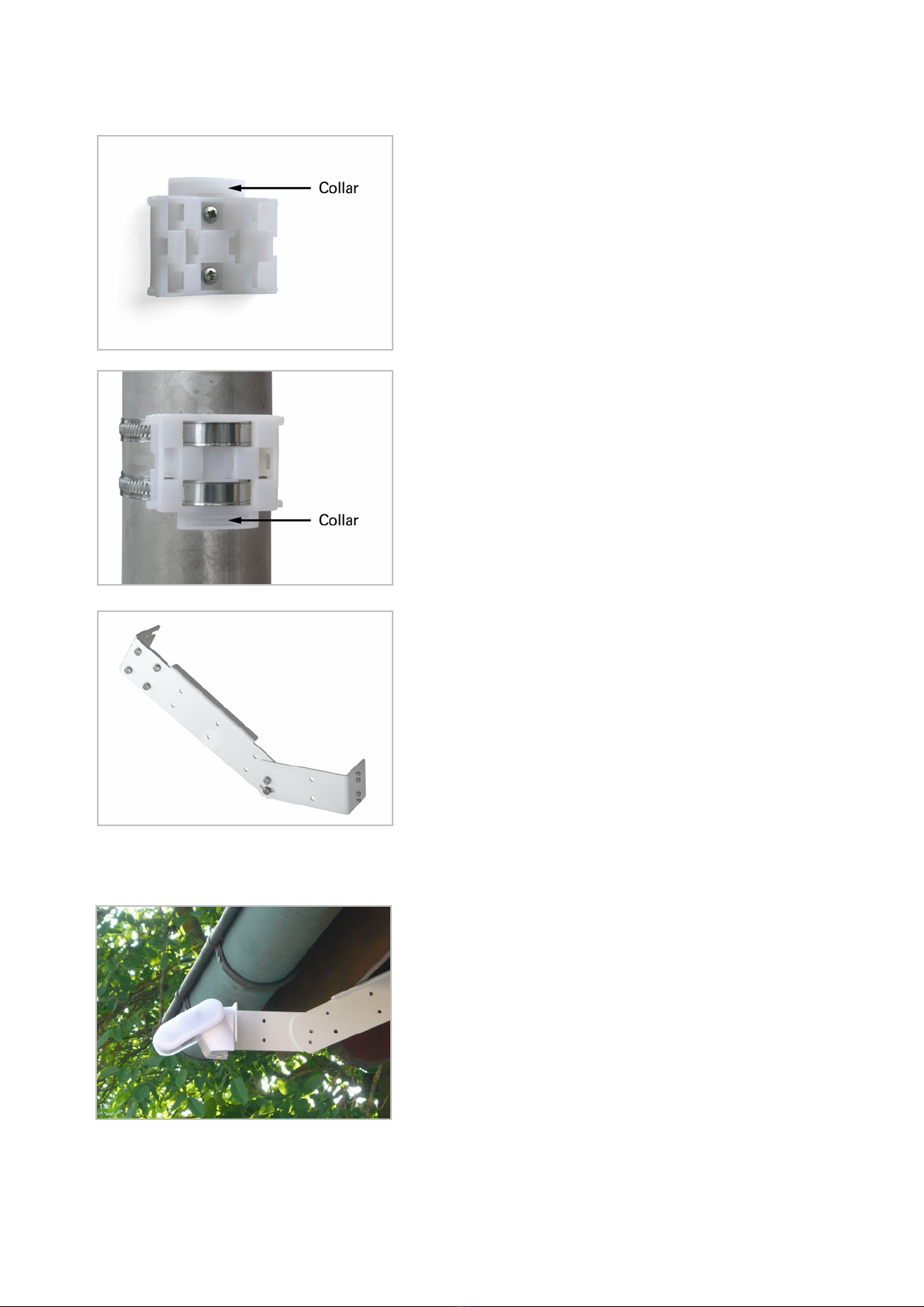
6
Fasten the mount vertically onto the wall or pole.
Fig. 5: When wall mounting: flat side on wall,
crescent-shaped collar upward.
Fig. 6: When pole mounting: curved side on pole,
collar downward.
Fig. 7: An additional, optional accessory
available from Elsner Elektronik is an articulated
arm for flexible wall, pole or beam mounting of
the sensor.
Examples for the application of the hinge arm mounting:
Ex.1 (Fig. 8): With the hinge arm mounting, the
sensor projects from beneath the roof. Sun, wind
and precipitation can be measured unhindered by
the sensors.

7
Ex. 2 (Fig. 9a+b): Pole-mounting with mounting
brackets.
View of rear side and drill hole plan
Fig.10a: Dimensions of rear side of housing with bracket. Subject to change for technical
enhancement
Fig. 10b: Drill hole plan

8
Preparing the sensor
Fig. 11
The rain sensor cover snaps in on the left and right along the bottom edge (see Fig.).
Remove the cover. Proceed carefully, so as not to pull off the wire connecting the PCB in
the bottom part with the rain sensor in the cover (soldered cable connection in case of
230 V AC version, cable with plug in case of 24 V DC version).
Push the power supply and bus connection cable through the rubber seal on the bottom
of the sensor and connect voltage LN and bus +/- to the provided clamps.
Mounting the sensor
Close the housing by putting the cover back over the bottom part. The cover must snap
in on the left and right with a definite “click”.
Fig. 12: Make sure the cover and bottom part are
properly snapped together! This picture is
looking at the closed sensor from underneath.

9
Fig. 13: Push the housing from above into the
fastened mount. The bumps on the mount must
snap into the rails in the housing.
To remove it, the sensor can be simply pulled upwards out of the mount, against the
resistance of the fastening.
Notes on installation
Do not open the device if water (rain) might ingress: even some drops might damage
the electronic system.
Observe the correct connections. Incorrect connections may destroy the sensor or
connected electronic devices.
Maintenance
The sensor must regularly be checked for dirt twice a year and cleaned if necessary. In
case of severe dirt, the rain sensor may not work properly anymore.
As a precaution, the device should always be separated
from power supply for maintenance works (e.g. deactivate
or remove fuse).

10
Transmission protocol
Abbreviations
EIS types:
EIS 1 Switching 1/0
EIS 6 8 bit value
Flags:
C Communication
R Read
W Write
T Transmit
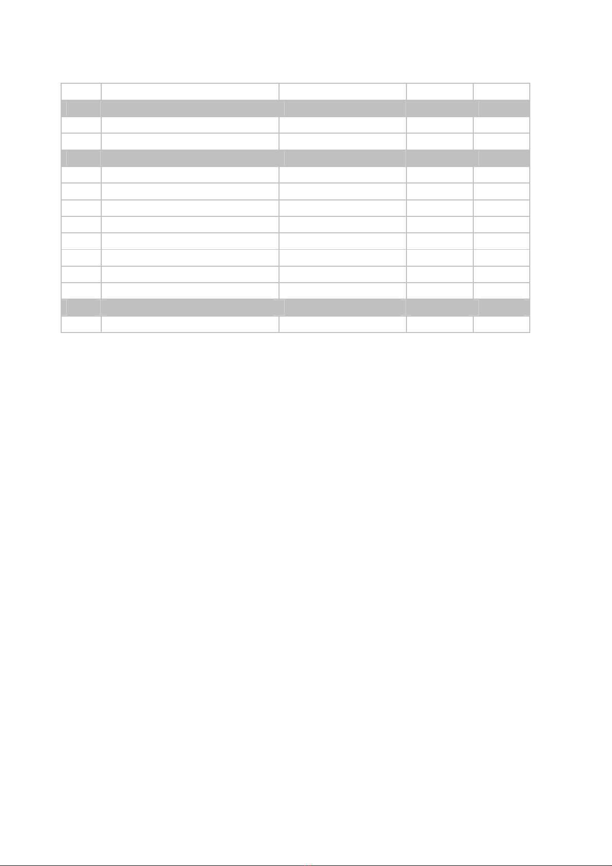
Listing of all communication objects
No. Name Function EIS type Flags
0 Rain Switching Output 1 C R T
1 AND Logic 1 Switching Output 1 C R T
2 AND Logic 1 8 bit Output A 6 C R T
3 AND Logic 1 8 bit Output B 6 C R T
4 AND Logic 2 Switching Output 1 C R T
5 AND Logic 2 8 bit Output A 6 C R T
6 AND Logic 2 8 bit Output B 6 C R T
7 AND Logic 3 Switching Output 1 C R T
8 AND Logic 3 8 bit Output A 6 C R T
9 AND Logic 3 8 bit Output B 6 C R T
10 AND Logic 4 Switching Output 1 C R T
11 AND Logic 4 8 bit Output A 6 C R T
12 AND Logic 4 8 bit Output B 6 C R T
13 OR Logic 1 Switching Output 1 C R T
14 OR Logic 1 8 bit Output A 6 C R T
15 OR Logic 1 8 bit Output B 6 C R T
16 OR Logic 2 Switching Output 1 C R T
17 OR Logic 2 8 bit Output A 6 C R T
18 OR Logic 2 8 bit Output B 6 C R T
19 OR Logic 3 Switching Output 1 C R T
20 OR Logic 3 8 bit Output A 6 C R T
21 OR Logic 3 8 bit Output B 6 C R T
22 OR Logic 4 Switching Output 1 C R T
11
No. Name Function EIS type Flags
23 OR Logic 4 8 bit Output A 6 C R T
24 OR Logic 4 8 bit Output B 6 C R T
25 Logic Input 1 Input 1 C R W
26 Logic Input 2 Input 1 C R W
27 Logic Input 3 Input 1 C R W
28 Logic Input 4 Input 1 C R W
29 Logic Input 5 Input 1 C R W
30 Logic Input 6 Input 1 C R W
31 Logic Input 7 Input 1 C R W
32 Logic Input 8 Input 1 C R W
33 Software Version readable 6 C R
12
Setting of parameters
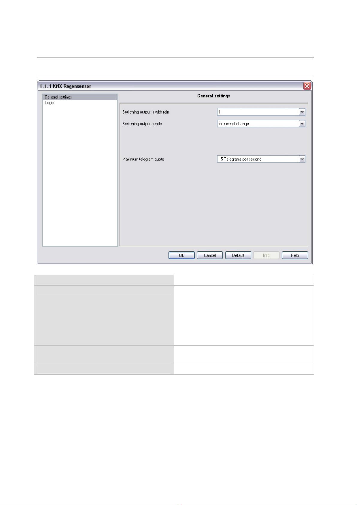
General settings
Switching output is with rain 0 • 1
Switching output sends • not
• in case of change
• in case of change to 1
• in case of change to 0
• in case of change and cyclically
• in case of change to 1 and cyclically
• in case of change to 0 and cyclically
send cyclically every
(only if sending “cyclically”)
5 sec … 2 h
Maximum telegram quota 1 • 2 • 3 • 5 • 10 • 20 Telegrams per second

13
Logic
Communication objects logic inputs do not release • release
AND logic:
--------------------------------
Logic 1 / 2 / 3 / 4 not active • active
Transmission delay of the switching outputs
after power up and programming
5 sec … 2 h
OR Logic:
--------------------------------
Logic 1 / 2 / 3 / 4 not active • active
Transmission delay of the switching outputs
after power up and programming
5 sec … 2 h

14
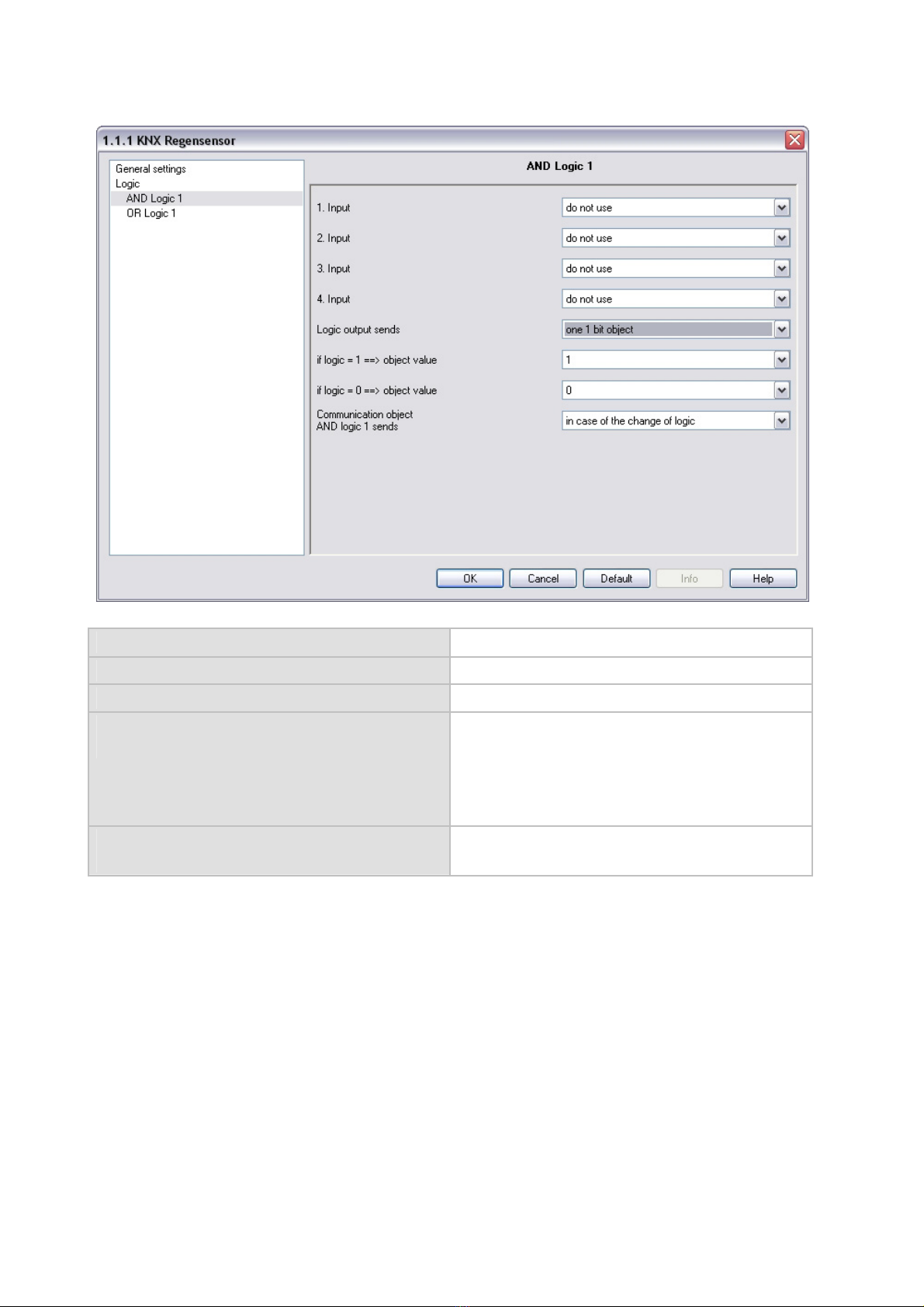
AND Logic 1 / 2 / 3 / 4
1. / 2. / 3. / 4. Input do not use • all switching events which the
sensor provides (see “Linkage inputs of the
AND logic”)
Logic output sends not • one 1 bit object • two 8 bit objects
15
If the logic output sends one 1 bit object:
Logic output sends one 1 bit object
If logic = 1 !object value 1 • 0
If logic = 0 !object value 1 • 0
Communication object
AND logic 1 sends
• in case of the change of logic
• in case of the change of logic to 1/0
• in case of the change of logic and cyclically
• in case of the change of logic to 1/0 and
cyclically
send cyclically every
(only if sending “cyclically”)
5 sec … 2 h
16
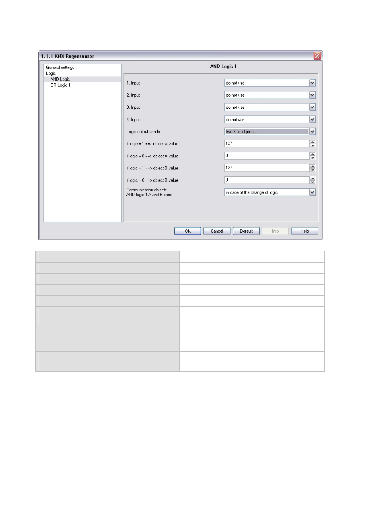
If the logic output sends two 8 bit objects:
Logic output sends two 8 bit objects
If logic = 1 !object A value 0 … 255
If logic = 0 !object A value 0 … 255
If logic = 1 !object B value 0 … 255
If logic = 0 !object B value 0 … 255
Communication objects
AND logic 1 A and B send
• in case of the change of logic
• in case of the change of logic to 1/0
• in case of the change of logic and cyclically
• in case of the change of logic to 1/0 and
cyclically
send cyclically every
(only if sending “cyclically”)
5 sec … 2 h

17
Linkage inputs of AND logic
do not use
Communication object logic input 1
Communication object logic input 1 inverted
Communication object logic input 2
Communication object logic input 2 inverted
Communication object logic input 3
Communication object logic input 3 inverted
Communication object logic input 4
Communication object logic input 4 inverted
Communication object logic input 5
Communication object logic input 5 inverted
Communication object logic input 6
Communication object logic input 6 inverted
Communication object logic input 7
Communication object logic input 7 inverted
Communication object logic input 8
Communication object logic input 8 inverted
Rain
no rain
OR Logic 1 / 2 / 3 / 4

18
1. / 2. / 3. / 4. Input do not use • all switching events which the
sensor provides (see “Linkage inputs of the OR
logic”)
Logic output sends not • one 1 bit object • two 8 bit objects
If the logic output sends one 1 bit object:
Logic output sends one 1 bit object
If logic = 1 !object value 1 • 0
If logic = 0 !object value 1 • 0
Communication object
OR logic 1 sends
• in case of the change of logic
• in case of the change of logic to 1/0
• in case of the change of logic and cyclically
• in case of the change of logic to 1/0 and
cyclically
send cyclically every
(only if sending “cyclically”)
5 sec … 2 h
If the logic output sends two 8 bit objects:
Logic output sends two 8 bit objects
If logic = 1 !object A value 0 … 255
If logic = 0 !object A value 0 … 255
If logic = 1 !object B value 0 … 255
If logic = 0 !object B value 0 … 255

19
Communication objects
AND logic 1 A and B send
• in case of the change of logic
• in case of the change of logic to 1/0
• in case of the change of logic and cyclically
• in case of the change of logic to 1/0 and
cyclically
send cyclically every
(only if sending “cyclically”)
5 sec … 2 h
Linkage inputs of OR logic
The linkage inputs of the OR logic correspond with the parameters of the AND logic.
The OR logic is additionally provided with the following inputs:
AND logic output 1
AND logic output 1 inverted
AND logic output 2
AND logic output 2 inverted
AND logic output 3
AND logic output 3 inverted
AND logic output 4
AND logic output 4 inverted
Table of contents
Other Elsner Accessories manuals

Elsner
Elsner Cala KNX AQS/TH Guide

Elsner
Elsner 71300 Guide

Elsner
Elsner Vari KNX 3L Guide

Elsner
Elsner KNX L User manual

Elsner
Elsner KNX T-UP gl Guide

Elsner
Elsner Vari KNX 3L-TH-D Guide

Elsner
Elsner Leak User manual

Elsner
Elsner KNX VOC-UP basic Guide

Elsner
Elsner KNX AQS/TH-B-UP Series Guide

Elsner
Elsner KNX LW Series User manual


Popular Accessories manuals by other brands


SIL
SIL GTIS Power Systems Villager III User instructions

BASETech
BASETech 2106308 operating instructions

texet
texet PB5600 instruction manual

S+S Regeltechnik
S+S Regeltechnik Photosgard RHKF Series Operating Instructions, Mounting & Installation

Smart Caregiver
Smart Caregiver 433-MS manual

Gardena
Gardena 19030 Operator's manual


