manuals.online logo
Brands
  1. Home
  2. •
  3. Brands
  4. •
  5. EMC
  6. •
  7. Enclosure
  8. •
  9. EMC CLARiiON DAE2 User manual

EMC CLARiiON DAE2 User manual

PARTS CHECKLIST FOR BASIC CONFIGURATION
Before you start, be sure you have available the necessary materials listed
below. Most required parts were provided with your system, but some are
shipped with particular components (and configurations) and others are
shipped separately.
❑One or more DAE2 disk enclosures
❑EMC-approved disk drives
For a list of supported RAID disks, refer to the EMC Storage Systems
CX-Series Disk and Software Matrix (P/N 014003111), available on the
Powerlink website.
❑If your DAE2 is not already installed in a rackmount cabinet
• One or more rails kits, and
•theEMC Rails and Enclosures Installation Guide for 19-inch NEMA
Cabinets (P/N 014003082)
❑Fibre Channel copper cables for connecting the DAE2 to SPE or DPE2
storage processors, or for connecting multiple DAE2s to each other
(2 per DAE2)
❑EMC DAE2 Hardware Documentation CD (P/N 068090607)
❑If you will use EMC Navisphere®Manager to manage the DAE2 with
an EMC CX-Series storage system
•TheConfiguration and Planning Guide appropriate for your system.
These manuals are available on Powerlink and the appropriate
Hardware Documentation CD.
•EMC Navisphere Manager Version 6.X Administrator’s Guide
(P/N 069001125) available on the EMC Navisphere Manager 6.X
Documentation CD (P/N 068090604).
❑If you are adding a DAE2 to a Celerra Network Attached Storage
system, be sure you have the appropriate documentation for that
system. You can find Celerra manuals on the EMC PowerLink
website http://powerlink.emc.com. Once logged in to Powerlink,
select Products > Networked Storage> Network Attached Storage
(NAS) > Celerra Systems > Celerra Manuals, Product Guides,
Configuration Guides, etc.
BEFORE YOU START
IMPORTANT Be sure you have completed all of the following site
and configuration preparations before you attempt to set up your
DAE2s.
1. Confirm that your facility has appropriate electrical wiring in
place to accommodate your cabinet’s power cables.
The standard 40U EMC cabinet includes two 240-volt ac power
cables. To support all DAE2 high-availability features, you must
connect each power outlet to a different circuit.
2. If you will connect the DAE2 to a storage device such as a CX-Series
storage processor enclosure (SPE) or disk processor enclosure
(DPE2), make sure the device is installed in the cabinet and set up.
Refer to the Setup Guide or Hardware Reference for the device.
3. If you will use EMC Navisphere Manager to monitor DAE2 status,
make sure that Navisphere Manager version 6.1 or higher is set up.
Refer to the EMC Navisphere Manager Version 6.X Administrator’s
Guide and the appropriate Release Notes as necessary.
4. If your DAE2 is not already installed in a cabinet, do so now. The
EMC Rails and Enclosures Installation Guide for 19-inch NEMA Cabinets
describes how to install a 3U device like the DAE2 in EMC’s standard
cabinet.
You can add DAE2 enclosures to active storage systems without
powering down the existing system.
Step 1
Set DAE2 Enclosure Address(es)
Set the enclosure address (EA) on each DAE2 in a given loop to a unique
number. We strongly suggest that you number enclosures consecutively. Refer
also to the illustrations in Step 2.
NOTE Do not configure an ATA model DAE2 as EA 0, loop 0. ATA
enclosures do not support the boot and SPS requirements of the first disk
array in a storage system.
An integrated disk-and-processor enclosure, such as a DPE2, is always the
first disk enclosure on the first loop (0,0).
Step 2
Set Up Fibre Channel Loops
Connect multiple DAE2s in paired loops. (A Fibre Channel loop is sometimes
called a bus.) One loop connects the SP A/LCC A (right) side of the system;
the SP B/LCC B loop shares disk drives with its counterpart.
Cable the expansion connector (EXP) of a DAE2 to the primary connector
(PRI) of the next DAE2 you want on the loop.
The primary connector of the first DAE2 in the loop is reserved for the storage
processor.
The first configuration on the right shows two redundant DAE2 loops
connected to a 2-Gigabit Disk Processor Enclosure (DPE2).
The illustration below shows an example storage-system configuration with
four pairs of redundant DAE2 loops: A0/B0, A1/B1, A2/B2, A3/B3.
P/N 014003104 REV A03
EMC2790
Enclosure
Address
Switch
+
_
0
Loop 0 Loop 0
Loop 1
Loop 0
Loop 1
Loop 0
Loop 1
Loop 1
Loop 0
Loop 1
Loop 0
Loop 1
Loop 1 Loop 1
LCC B LCC A
EA1/Loop 1
EA0/Loop 1
EA1/Loop 0
EA2/Loop 1
EA2/Loop 0
EA3/Loop 1
EA3/Loop 0
EXP EXP
PRI PRI
EA0/Loop 0
BE 1 BE 1
BE 0 BE 0
EMC2720s
LCC B
Loop 3
Loop 3
Loop 1
Loop 1
Loop 2
Loop 2
Loop 0
Loop 0
EA1/Loop 2
EA1/Loop 0
EA0/Loop 2
EA0/Loop 0
EA1/Loop 3
EA1/Loop 1
EA0/Loop 3
EA0/Loop 1
EMC2709S
SPS B SPS A
LCC A
SP B
SP A
Loop 3
Loop 3
Loop 1
Loop 1
Loop 2
Loop 2
Loop 0
Loop 0
EMC CLARiiON 2-Gigabit Disk-Array Enclosure (DAE2) Setup and Cabling Guide
Step 3
Connect the DAE2 to a
Storage Processing Device
If you are connecting the first DAE2 in a loop to a storage processing device,
such as an SPE or DPE2:
1. Plug one end of a copper cable into the primary (PRI) High
Speed Serial Data Connector (HSSDC) connector on each Link
Control Card (LCC) in the DAE2.
2. Plug the other end of the cables into the appropriate connector on the
storage processor device. For more information, refer to the Setup
Guide or the Hardware Reference for the device.
Step 4
Connect DAE2 Power Cords
1. Connect one end of an ac power cable to the power connector on
each DAE2 power supply.
2. Connect the other end to the nearest power outlet in the cabinet. For
high availability, connect the power supplies to opposing side power
strips so they do not share a single circuit.
In the CX600/CX700 SPE example above, the first DAE2 is connected to a
secondary power supply (SPS). In DPE2 configurations, you should not connect a
DAE2 to the SPS. Refer to the relevant Setup Guide or Hardware Reference for
device-specific configuration rules.
Step 5
Start DAE2s
1. Turn on the power for each DAE2 power supply.
2. If the cabinet power is not already on, be sure the other devices in the
system are correctly installed and ready for powerup; then
a. Plug the two 240-volt ac power cables into the power outlets in your
facility. We recommend connecting each power cable to a different
branch circuit. You must connect both power cables to the appropriate
power source. Connecting only one power source will degrade the
DAE2’s performance.
b. Turn on the circuit breakers on each of the cabinet’s side power
strips.
The green power lights on the front of the DAE2 chassis and on each disk
drive indicate that power is on; an amber chassis light indicates a fault.
If an amber light on the front of a DAE2 is lit, make sure the DAE2 is correctly
cabled, the enclosure addresses are correct, and the disks are completely
seated. Then refer to the fault code explanations in Chapter 3 of the DAE2
Hardware Reference, available on Powerlink and the DAE2 Hardware
Documentation CD. If you cannot determine any reasons for errors, contact
your DAE2 service provider.
YOUR NEXT STEP
Once your DAE2 is up and running, you can integrate the DAE2 into your
existing storage system, or initialize a new system. Refer to the EMC
Navisphere Manager Version 6.X Administrator’s Guide or the appropriate
checklist in the EMC Installation Roadmap (P/N 069001166).
The Installation Roadmap and other EMC CLARiiON® storage system setup
and administration manuals are available on http://powerlink.emc.com. Once
logged in to Powerlink, select Support > Document Library to find the
documentation you need.
These resources are available in case you encounter problems while setting up
or using the DAE2.
IF YOU NEED HELP
For questions about technical support and service, contact your service
provider.
If you have an EMC service contract, contact EMC Customer Service at USA
(800) 782-4362, Canada (800) 543-4782, or worldwide (508) 497-7901.
For questions about upgrades, contact your local sales office.
Copyright © 2003, 2004 EMC Corporation. All rights reserved.
EMC believes the information in this publication is accurate as of its publication date. However, the information
is subject to change without notice.
THE INFORMATION IN THIS PUBLICATION IS PROVIDED “AS IS.” EMC CORPORATION MAKES NO
REPRESENTATIONS OR WARRANTIES OF ANY KIND WITH RESPECT TO THE INFORMATION IN THIS
PUBLICATION, AND SPECIFICALLY DISCLAIMS IMPLIED WARRANTIES OF MERCHANTABILITY OR
FITNESS FOR A PARTICULAR PURPOSE.
Use, copying, and distribution of any EMC software described in this publication require an applicable software
license.
EMC2, EMC, CLARalert, CLARiiON, Navisphere, and PowerPath are registered trademarks and Access Logix,
MirrorView, SAN Copy, and SnapView are trademarks of EMC Corporation.
All other trademarks mentioned herein are the property of their respective owners.
January, 2004
EMC231
2
To other FC device
PRI
Connector
EMC1972
DAE2
DAE2
DAE2
DAE2
SPE
Power
Switch
/
Cord
Power
Switch/
Cord
EMC2166
Power LED
(Green)
Fault LED
(Amber)
Fault LED
(Amber)
Disk Activity
LED
(
Green
)
For questions about Use this resource
Storage-system
configurations and
configuration planning
EMC Storage Systems CX-Series Configuration and
Planning Guide
Hardware component
installation or maintenance
EMC 2-Gigabit Disk Enclosure (DAE2) Hardware
Reference
Storage Processor Hardware Reference(s) as
appropriate.
Managing the storage system EMC Navisphere Manager Revision 6.X
Administrator’s Guide and Release Notes
Last minute changes to
documentation
Appropriate Release Notes for your operating
system, application(s), and hardware
environment
Other EMC Enclosure manuals

EMC Connectrix EC-1100 System User manual

EMC

EMC Connectrix EC-1100 System User manual

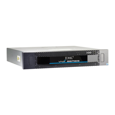
EMC VNXe User manual

EMC

EMC VNXe User manual

EMC CLARiiON CX700 Application guide

EMC

EMC CLARiiON CX700 Application guide

EMC CLARiiON DAE2P User manual

EMC

EMC CLARiiON DAE2P User manual

EMC CX200-Series Application guide

EMC

EMC CX200-Series Application guide

EMC FC4500 Application guide

EMC

EMC FC4500 Application guide

EMC CLARiiON DAE2P Application guide

EMC

EMC CLARiiON DAE2P Application guide

EMC CLARiiON CX700 Application guide

EMC

EMC CLARiiON CX700 Application guide

EMC CX4 Series User manual

EMC

EMC CX4 Series User manual

EMC CX700 SPE User manual

EMC

EMC CX700 SPE User manual

EMC VNXe3100 User manual

EMC

EMC VNXe3100 User manual

EMC DAE User manual

EMC

EMC DAE User manual

EMC HD400 Installation instructions

EMC

EMC HD400 Installation instructions

Popular Enclosure manuals by other brands

Antec Solution SLK3700AMB user manual

Antec

Antec Solution SLK3700AMB user manual

American Standard 4242.STE1 Specification sheet

American Standard

American Standard 4242.STE1 Specification sheet

Pulsar ARAD4 installation guide

Pulsar

Pulsar ARAD4 installation guide

Akasa Integral LAN user manual

Akasa

Akasa Integral LAN user manual

Joy-it ARMOR CASE BLOCK ACTIVE manual

Joy-it

Joy-it ARMOR CASE BLOCK ACTIVE manual

ARKY AED manual

ARKY

ARKY AED manual

Tyco Electronics AMP NETCONNECT AMPTRAC 1933443-1 instruction sheet

Tyco Electronics

Tyco Electronics AMP NETCONNECT AMPTRAC 1933443-1 instruction sheet

Icy Box IB-AC6025-3 Quick installation guide

Icy Box

Icy Box IB-AC6025-3 Quick installation guide

Inoi DW567 user manual

Inoi

Inoi DW567 user manual

Velux GEL VEA installation instructions

Velux

Velux GEL VEA installation instructions

Gembird EE2280-U3C-03 user manual

Gembird

Gembird EE2280-U3C-03 user manual

Cronologic Ndigo Crate user guide

Cronologic

Cronologic Ndigo Crate user guide

Chatsworth Products CUBE-iT installation instructions

Chatsworth Products

Chatsworth Products CUBE-iT installation instructions

JL Audio M770-ETX-CG-WH installation guide

JL Audio

JL Audio M770-ETX-CG-WH installation guide

Cheval ARION 600W Series Assembly guide

Cheval

Cheval ARION 600W Series Assembly guide

YORKVILLE NX300P owner's manual

YORKVILLE

YORKVILLE NX300P owner's manual

Graziadio & C. GDA406300 Assembly instructions

Graziadio & C.

Graziadio & C. GDA406300 Assembly instructions

Evolveo Tiny N1 manual

Evolveo

Evolveo Tiny N1 manual

manuals.online logo
manuals.online logoBrands
  • About & Mission
  • Contact us
  • Privacy Policy
  • Terms and Conditions

Copyright 2025 Manuals.Online. All Rights Reserved.