EMC VNXe3100 User manual

This document describes how to replace a storage processor (SP) in a VNXe3100 or
VNXe3150 disk processor enclosure (DPE).
Before you start
1. Before you begin the procedure, refer to your EMC® VNXe™ online help (Servicing
your system > Adding or replacing faulted hardware components > Replace a faulted
hardware component) for instructions on how to identify failures, order new parts, and
handle hardware components.
2. Unpack the replacement SP and place it on a flat, static-free work surface large
enough to hold it and the faulted SP.
Save the packing material to return the faulted SP.
Tasks to replace an SP
◆Task 1: Preparing the storage processor (SP) for service ............................................ 2
◆Task 2: Remove the SP assembly............................................................................... 3
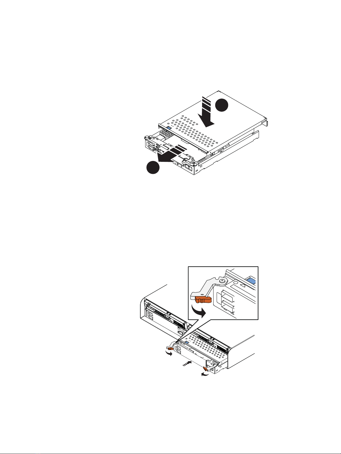
◆Task 3: Remove the SP top cover ............................................................................... 4
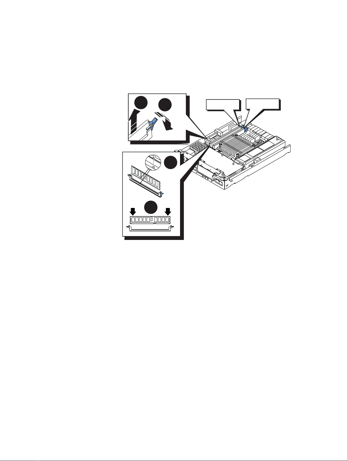
◆Task 4: Transfer the memory modules ....................................................................... 5
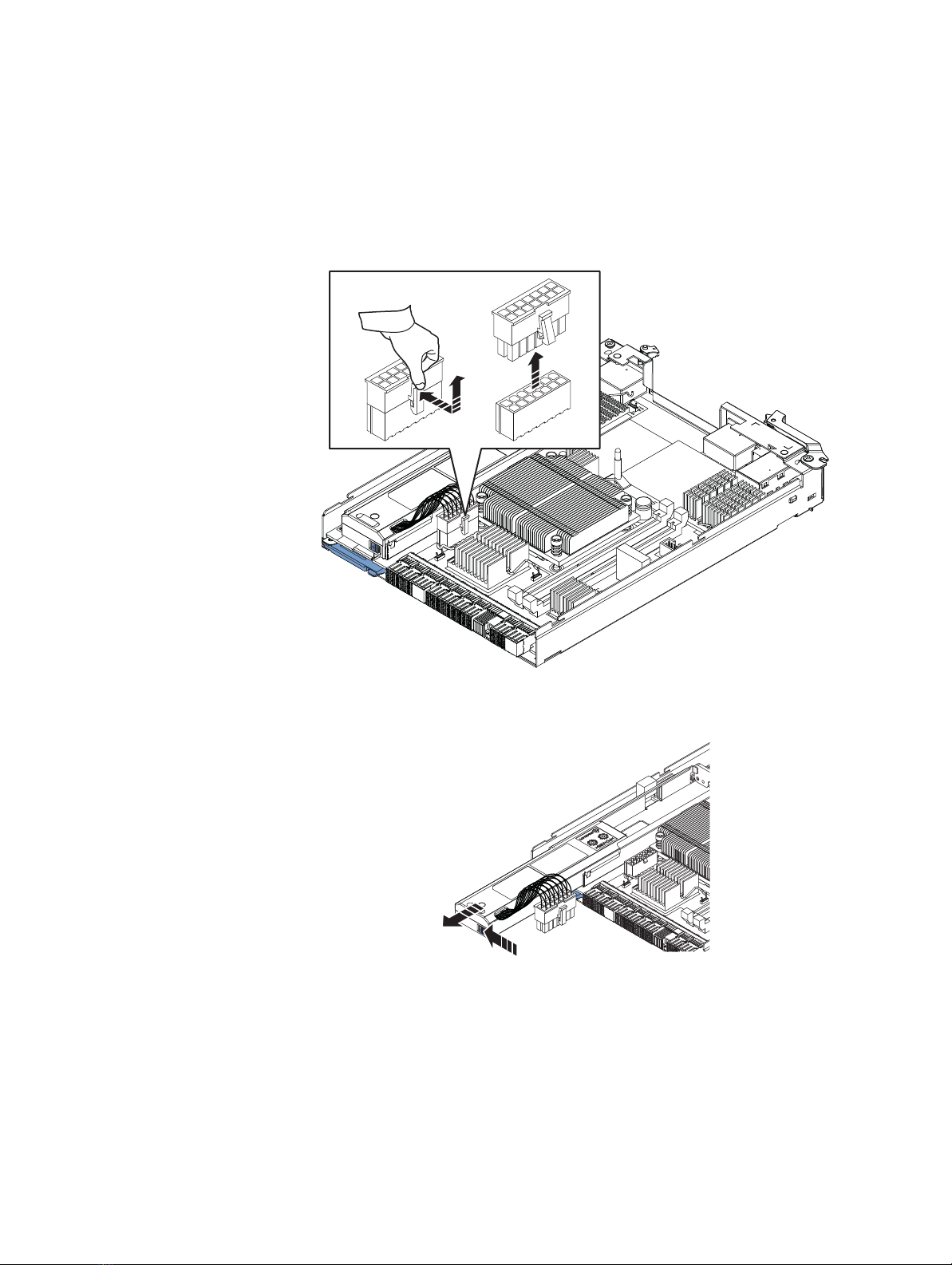
◆Task 5: Transfer the battery backup unit (BBU) .......................................................... 6
◆Task 6: Transfer the I/O module or filler module ........................................................ 7
◆Task 7: Transfer the SSD disk module........................................................................ 9
◆Task 8: Replace the SP top cover ............................................................................. 10
◆Task 9: Install the replacement SP assembly ........................................................... 10
◆Task 10: Reboot the replacement SP ....................................................................... 11
◆Task 11: Verify the operation of the replacement SP ................................................ 11
◆Task 12: Return the faulted SP................................................................................. 11
EMC® VNXe3100/VNXe3150
Replacing a Storage Processor
P/N 300-012-218
REV 02

2 EMC VNXe3100/VNXe3150 — Replacing a Storage Processor
Tasks to replace an SP
Task 1: Preparing the storage processor (SP) for service
IMPORTANT
To protect your VNXe system form accidental data loss while you replace an SP, you must
prepare the SP for service before you remove it. You prepare an SP for service by putting it
in Service mode. Both SPs must not be in Service mode at the same time.
1. Open Unisphere™ and select Settings, then Service System.
2. Log in with your service password.
3. In the System Components column, select the faulted storage processor (A or B).
4. Under Service Actions, select Enter Service Mode, then Execute service action.
5. In the Service Confirmation dialog box click OK.
Putting an SP into Service mode takes about 10 minutes to complete. The storage
processor fault LED will flash alternating amber and blue while the SP remains in
Service mode and is receiving active power.
6. Wait until the SP fault LED is flashing alternating amber and blue before continuing to
the next task.
1
1 GBE
01
X4
6Gb SAS
6Gb SAS
23
1
0
e3e0 e1 e2
1 GbE
SP fault

Tasks to replace an SP
EMC VNXe3100/VNXe3150 — Replacing a Storage Processor 3
Task 2: Remove the SP assembly
To replace a SP, you must remove the SP assembly from the chassis, and then transfer the
memory modules, the battery backup unit (BBU), the I/O module, and the solid state disk
to the replacement SP assembly.
Follow these steps to remove the SP assembly:
DO NOT REMOVE an SP while the “Unsafe to remove SP” LED is on. If your
system has a single SP, DO NOT REMOVE the SP if the “Unsafe to remove” LED
for the cache protection module is on. The light indicates that you may interrupt
a vital system or data-caching process.
1. Disconnect the network and all other cables from the back of the faulted SP assembly.
Do not remove
any cables from the other storage processor assembly.
Mark the cables with the port numbers from which you removed them.
The SP assembly comes completely out of the chassis. In addition to holding the
latches, be prepared to support the SP assembly to avoid dropping it.
2. Locate the two orange release levers on the SP assembly latches.
3. Squeeze the levers to release the latches and pull the latches outward until they are
fully extended and the SP assembly is released from the chassis.
4. Use the latches to slide the assembly about
half-way
out of the enclosure.
5. Use both hands to support the assembly and pull it fully out of the enclosure.
6. Place the assembly on the clean, flat anti-static work surface beside the replacement
assembly.
CL4682

4 EMC VNXe3100/VNXe3150 — Replacing a Storage Processor
Tasks to replace an SP
Task 3: Remove the SP top cover
Remove the SP cover from
both
the faulted SP and the replacement SP.
1. Press the blue button on the cover.
2. Push the cover straight back 1/4 inch.
3. Lift the cover up.
2
3
1
CL4683

Tasks to replace an SP
EMC VNXe3100/VNXe3150 — Replacing a Storage Processor 5
Task 4: Transfer the memory modules
Remove the memory modules from the faulted SP and install them in the replacement SP:
1. Rotate the memory module latches outward to release the module from the socket.
2. Touching only the outside edges, pull the module directly out of the socket.
3. Handling only the outside edges of the module, align the module with the socket on
the replacement SP.
The socket and module are keyed to prevent incorrect alignment.
4. Firmly push the module directly into the socket.
The latches snap to the closed position when the module is fully inserted in its socket.
21
3
4
DIMM 0 DIMM 1

6 EMC VNXe3100/VNXe3150 — Replacing a Storage Processor
Tasks to replace an SP
Task 5: Transfer the battery backup unit (BBU)
Remove the battery backup unit from the faulted SP, and install it in the replacement SP:
1. Press the top of the white tab on the BBU cable connector to release it, then carefully
pull the cable connector from the processor board.
You may need to gently rock the connector to remove it.
2. Push the blue tab to the left to release the BBU, and then carefully pull it from its
carrier on the CPU board.
3. Lift the BBU out and away from the canister.
CL4651
CL4650

Tasks to replace an SP
EMC VNXe3100/VNXe3150 — Replacing a Storage Processor 7
4. Slide the BBU into the canister on the replacement SP until the release tab catches.
5. Attach the BBU cable connector to the replacement SP CPU board.
Task 6: Transfer the I/O module or filler module
Remove the I/O module (or filler module) from the faulted SP and install it in the
replacement SP:
1. Carefully lift the blue latch on the faulted processor board until it ejects the I/O or filler
module from the connector.
2. Lift the module out and away from the canister.
3. Angle the I/O module slightly so it fits into the canister on the replacement SP and
align it with the blue alignment pins.
CL4684
CL4685
21
CL4688

8 EMC VNXe3100/VNXe3150 — Replacing a Storage Processor
Tasks to replace an SP
Do not attempt to seat the I/O module into the CPU connector while you are holding
the I/O module at an angle. Doing so will damage the connections. The I/O module
should be flat before you attempt to seat the connector.
4. With the module aligned and parallel to the CPU board, press the latch down to fully
seat the module in the connector.
5. Push down on the force point indicated on the I/O module to ensure that the module
is completely seated on the processor board.
2
3
1
CL4689

Tasks to replace an SP
EMC VNXe3100/VNXe3150 — Replacing a Storage Processor 9
Task 7: Transfer the SSD disk module
Remove the solid state disk from the faulted SP and install it in the replacement SP:
1. Unlatch the solid state disk by pulling the blue tab away from the bottom of the faulted
SP.
2. Pull the SSD out of the slot.
3. Slide the solid state disk into the slot in the replacement SP, making sure that the
latch snaps in place.
1 2 4
CL4653
3
CL4652
431 2

10 EMC VNXe3100/VNXe3150 — Replacing a Storage Processor
Tasks to replace an SP
Task 8: Replace the SP top cover
Replace the top cover on both the replacement and faulted SPs:
1. Align the cover tabs with the notches in the canister.
2. Slide it forward 1/4 inch until the tab secures the cover.
Task 9: Install the replacement SP assembly
1. Pull out the latches on each side of the replacement SP assembly and make sure they
stay in the open position.
2. Align the SP assembly with the chassis opening and push it straight into the chassis.
The latches begin to close when they contact the chassis edges.
3. Close the right and left latches to fully seat the SP assembly in the chassis.
An audible click indicates that the latches are secure.
4. Reconnect the cables to the back of the SP assembly being sure to connect all cables
to the same ports from which you removed them on the faulted SP.
The SP begins powering up immediately after connection to an active AC power
source.
2
1
CL4686
CL4687

Tasks to replace an SP
EMC VNXe3100/VNXe3150 — Replacing a Storage Processor 11
Task 10: Reboot the replacement SP
Once you have installed the replacement SP and returned the SP assembly to the chassis,
reboot the recently serviced (replacement) SP to ensure that it leaves Service mode:
1. From Unisphere, select Settings, then Service System.
2. Log in with your service password.
3. In the System Components column, select the storage processor currently in Service
mode.
4. Under Service Actions, select Reboot, then Execute service action.
It may take up to 12 minutes for the system to complete its reboot to return to Normal
mode and restart the servers.
5. Refresh your browser, or follow the on-screen instructions, to bring the software out of
Service mode and restore full-function Unisphere.
Task 11: Verify the operation of the replacement SP
Verify that the replacement SP is recognized by your system, and operating correctly:
1. In Unisphere™, select System, then System Health.
2. Select the replacement SP in the Component list or the graphical view:
• In the Component list, the SP should be marked with a status OK icon:
• In the graphical view, the SP should be highlighted green.
If the system health monitor shows the SP as faulted, contact your service provider.
Task 12: Return the faulted SP
1. Package the faulted SP in the shipping box that contained the replacement SP, and
seal the box.
2. From Unisphere, click Support > Need more Help? > Customer replaceable parts >
Return a customer replaceable part to enter the EMC Online Support website. The site
includes detailed instructions on how to return faulted parts.
If your screen does not show the Return a customer replaceable part option, contact
your service provider for instructions on what to do next.
3. Follow the on-screen instructions. The website includes a printable return label and
box pickup information.
4. Attach the shipping label, and contact the appropriate person to pick up the parts.

12 EMC VNXe3100/VNXe3150 — Replacing a Storage Processor
Tasks to replace an SP
Copyright © 2011-2012 EMC Corporation. All rights reserved. Published in the USA.
Published August, 2012
EMC believes the information in this publication is accurate as of its publication date. The information is subject to change without
notice.
The information in this publication is provided as is. EMC Corporation makes no representations or warranties of any
kind with respect to the information in this publication, and specifically disclaims implied warranties of
merchantability or fitness for a particular purpose. Use, copying, and distribution of any EMC software described in this
publication requires an applicable software license.
EMC2, EMC, and the EMC logo are registered trademarks or trademarks of EMC Corporation in the United States and other countries.
All other trademarks used herein are the property of their respective owners.
For the most up-to-date regulatory document for your product line, go to the technical documentation and advisories
section on EMC Online Support.
Other manuals for VNXe3100
3
This manual suits for next models
1
Table of contents
Other EMC Enclosure manuals

EMC
EMC CLARiiON DAE2P User manual

EMC
EMC Connectrix EC-1100 System User manual

EMC
EMC FC4500 Application guide

EMC
EMC CX200-Series Application guide

EMC
EMC CLARiiON DAE2P Application guide

EMC
EMC CLARiiON CX700 Application guide

EMC
EMC CLARiiON DAE2 User manual

EMC
EMC CX700 SPE User manual

EMC
EMC VNXe User manual

EMC
EMC HD400 Installation instructions