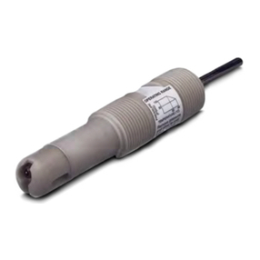
Cageless 249VS Sensor
Instruction Manual
Form 5831
November 2007
9
properly. Replace the displacer rod/driver assembly,
if necessary.
CAUTION
If the displacer is to be disconnected
from the displacer rod before being
removed from the process vessel,
provide a suitable means of
supporting the displacer to prevent it
from dropping into the process vessel
and being damaged.
1. After following the proper procedure to remove
the torque tube arm assembly and the displacer from
the process vessel, move the sensor assembly to a
suitable maintenance area. Support the assembly to
avoid damage to the displacer, displacer stem,
displacer rod assembly, and associated parts.
2. Remove the controller/transmitter and displacer
(key 9).
3. Using the proper tool, loosen and then remove
the upper driver bearing bolt (key 4). Lift the
displacer rod/driver assembly from the knife edge of
the driver bearing (key 3). Separate the displacer
rod/driver assembly from the end of the torque tube
assembly (key 10).
4. If necessary, remove the driver bearing by
removing the lower bearing driver bolt. Install a new
driver bearing and bolts.
5. If necessary, replace the displacer rod/driver
assembly and install it on the knife edge of the driver
bearing. Carefully fit the keyed shaft on the bearing
end of the displacer rod into a socket on the outside
of the welded end of the torque tube assembly.
6. Install the controller/transmitter. Calibrate the
controller/transmitter following the procedures given
in the controller/transmitter instruction manual.
Replacing the Torque Tube
Corrosion or leakage through the outer end of the
torque tube is evidence of deterioration in the torque
tube assembly (key 10) or torque tube end gasket
(key 17). Erratic or nonexistent rotary shaft output
may occur if the socket on the inner end of the
torque tube assembly does not engage the bearing
end of the displacer rod assembly (key 14).
CAUTION
Support the sensor assembly to avoid
damage to the displacer, displacer
stem, displacer rod assembly, and
associated parts.
1. After following the proper procedure to remove
the sensor assembly from the process vessel, move
the sensor assembly to a suitable maintenance area.
2. Remove the controller/transmitter and displacer
(key 9).
3. Remove the nuts (key 13) and retaining flange
(key 12) holding the positioning plate (key 21) at the
end of the torque tube arm.
CAUTION
If the displacer is still attached to the
displacer rod at this point, be careful
not to let the torque tube assembly
slip when using the screwdriver
leverage procedure in steps 4 and 6.
Sudden release of the displacer would
cause damage.
4. Remove the positioning plate (key 21) by freeing
its two lugs.
The vertical lug fits into a hole in the flange of the
torque tube arm (top of figure 9). The horizontal lug
(hidden behind the screwdriver at the bottom of
figure 9) fits into a slot in the outer tube end of the
torque tube assembly (the figure 9 exploded view
shows this lug to the right of the outer tube end).
The positioning plate may be pried away from the
torque tube arm and outer tube end if the displacer
already has been disconnected from the displacer
rod. However, if the displacer is still connected to the
displacer rod, place a screwdriver blade in the slots
of the positioning plate and outer tube end as shown
in figure 9. Slowly turn the positioning plate to
release its lug from the torque tube arm. Then,
carefully turn the plate back to allow the displacer to
come to rest and slip the other lug of the plate from
its slot in the outer tube end.
5. Pull the torque tube assembly and tube end
gasket out of the torque tube arm.
