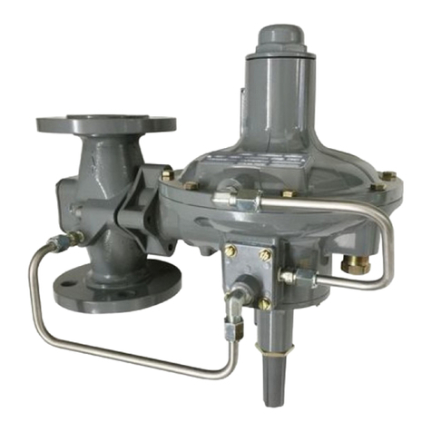
Introduction
This installation guide provides instructions for installation,
startup and adjustment. To receive a copy of the instruction
manual, contact your local Sales Ofce or view a copy at
www.sher.com. For further information, refer to Type 99
Instruction Manual, D100260X012.
PED Category
This product may be used as a pressure accessory with
pressure equipment in the following Pressure Equipment
Directive categories. It may also be used outside of the
Pressure Equipment Directive using sound engineering practice
(SEP) per table below. For information on the current PED
revision see Bulletin: D103053X012.
PRODUCT SIZE PED LIMITATION CATEGORY
DN 50 / NPS 2 19.0 bar / 275 psig I
Type 99L - Type 99 with Type 61L pilot which has
5 mbar to 1.4 bar / 2 in. w.c. to 20 psig pressure range.
Type 99LD - Type 99 with Type 61LD pilot which
has a narrower proportional band than the standard
Type 61L pilot.
Type 99LE - Type 99 with Type 61LE pilot which
has a broader proportional band than the standard
Type 61L pilot.
Type 99H - Type 99 with Type 61H pilot which has
0.69 to 4.5 bar / 10 to 65 psig pressure range.
Type 99HP - Type 99 with Type 61HP pilot has 2.4 to
6.9 bar / 35 to 100 psig pressure range.
DN 50 / NPS 2 body with NPT, CL125 FF, CL150 RF,
CL250 RF, CL300 RF end connections
(1)
11.0 bar / 160 psig with Type 61LD pilot;
27.6 bar / 400 psig with Type 61L, 61LE or 61H pilot
69.0 bar / 1000 psig with Type 61HP pilot, along with
Type 1301F pilot supply regulator and
Type H110 relief valve (13 mm / 1/2 in. orice only)
(1)
See Table 1
(1)
See Table 2
(1)
Operating: 6.9 bar / 100 psig
Emergency: 7.6 bar / 110 psig
(1)(2)
3.4 bar / 50 psi
with special steel closing cap
6.9 bar / 100 psi
See Table 2
Maximum Rated Travel
6.4 mm / 1/4 in.
(1)
Nitrile (NBR)/Neoprene (CR)/Nylon (PA):
-29 to 82°C / -20 to 180°F
-18 to 149°C / 0 to 300°F
!
WARNING
Clean out all pipelines before installation of the regulator and
check to be sure the regulator has not been damaged or has
collected foreign material during shipping. For NPT bodies,
apply pipe compound to the external pipe threads. For anged
bodies, use suitable line gaskets and approved piping, and
bolting practices. Install the regulator in any position desired,
unless otherwise specied, but be sure ow through the body
is in the direction indicated by the arrow on the body.
Note
1. The pressure/temperature limits in this installation guide and any applicable standard or code limitation should not be exceeded.
2. For stability or overpressure protection, a pilot supply regulator may be installed in the pilot supply tubing between the main valve and pilot.
Type 99
Installation Guide
D100260X014
English – February 2016
