manuals.online logo
Brands
  1. Home
  2. •
  3. Brands
  4. •
  5. Emerson
  6. •
  7. Controllers
  8. •
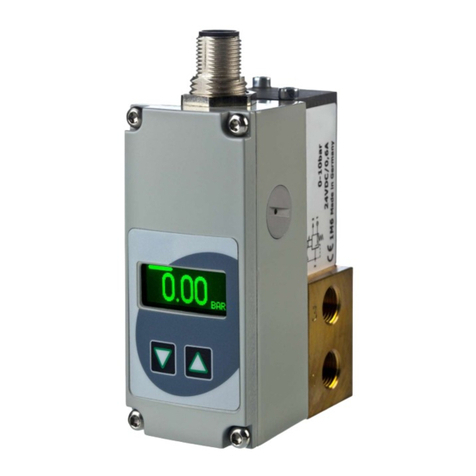
  9. Emerson P159A Series Installation and operating instructions

Emerson P159A Series Installation and operating instructions

ASCO Valves®E314794 - 08/2021 All Rights Reserved. I&M V_9953_AC
©ASCO, L.P. 160 Park Avenue, Florham Park, New Jersey 07932 www.emerson.com Page 1 of 4
I&M V_9953_AC
Installation & Maintenance Instructions
PUSH-TYPE LINEAR ACTUATOR
WITH ON/OFF OR HIGH/LOW/OFF OPERATION
WITH GENERAL PURPOSE OR WATERTIGHT ENCLOSURE
WARNING
To prevent the possibility of death, serious injury or
property damage, the actuator must be installed and
serviced only by a qualied service technician avoiding the
following hazards:
• Electrical hazard: Turn o󰀨 all electrical power to actuator.
• Risk of electric shock: More than one disconnect switch
may be required to de-energize the device for servicing.
• Pressure hazard: Depressurize valve and vent hazardous
or combustible uid to a safe area before inspection or
removal of the actuator or valve from service.
• Explosion, re or toxic gas hazards: Extinguish all open
ames and avoid any type of sparking or ignition during
leakage testing.
AVERTISSEMENT
An de prévenir le risque de décès, de graves blessures
ou de dommage matériel, l’actionneur doit être installé et
entretenu exclusivement par un technicien de maintenance
qualié, en évitant les dangers suivants:
• Danger électrique: Coupez toutes les sources
d’alimentation électrique de l’actionneur.
• Risque d’électrocution: Plus d’un interrupteurs de
coupure peuvent s’avérer nécessaires pour mettre
l’appareil hors tension pour les opérations de
maintenance et de réparation.
• Danger lié à la pression: Dépressurisez la vanne et
évacuez le uide dangereux ou combustible vers une
zone sécurisée avant d’inspecter ou de retirer la vanne
du service.
• Risques d’explosion, d’incendie et de gaz toxiques:
Éteindre toutes les ammes nues et éviter tout type
d’étincelle ou d’ignition pendant les essais de détection
de fuite.
Service Notices
See separate _158A Series Gas Valve or V710_B Gas Valve Installation
and Maintenance Instructions for information on: Operation, Positioning,
Mounting, Piping, Strainer or Filter Requirements, Flow Controls,
Preventive Maintenance and Cause of Improper Operation.
Do not install the P159A Series Actuator with general purpose enclosure
(Type 1) in a location subject to weather, wash down or other sources
for water ingress. Use Type 4 version of the actuator with watertight
enclosure for these locations.
DESCRIPTION
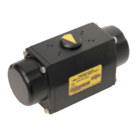
The P159A Series Hydraulic Actuator is a self-contained linear, push-type
actuator which extends when powered and retracts by spring force upon power
interruption.

equipment, commonly to open and close a valve or both a valve and damper.
The P159A Series Actuator positions _158A Series Gas Valves or V710_B
Series Gas Valves.
OPERATION
P159A1 - ON/OFF ACTUATOR
Application of electrical power simultaneously drives an electric pump and
closes a normally-open dump valve, resulting in up to 1100 N (250 lbf) of
force on the actuator stem. This extends the actuator stem and attached valve
poppet, to open the valve and/or damper.
Upon reaching the fully extended position, a travel limit switch interrupts
power to the electric motor while maintaining power to the dump valve, thus
stabilizing hydraulic pressure to hold shaft position. Position indicators on
both sides of the actuator show the actual position of the valve stem. Upon
power interruption, the dump valve opens, releasing hydraulic pressure and
allowing the return spring to retract the stem and close the valve fully. Closing
time is one second or less.
SERIES
P159A
P159A2 - HIGH/LOW/OFF ACTUATOR
Application of electrical power simultaneously drives an electric pump and
closes a normally-open dump valve and control valve, resulting in up to 1100
N (250 lbf) of force on the actuator stem. This extends the actuator stem and
attached valve poppet, to open the valve and/or damper.
             
the motor while maintaining power to the dump and control valves, thus
stabilizing hydraulic pressure to hold shaft position.


Upon reaching the fully extended position, a travel limit switch interrupts
power to the electric motor while maintaining power to the dump valve and
control valves, thus stabilizing hydraulic pressure to hold shaft position.


Position indicators on both sides of the actuator show the actual position of
the valve stem.
Upon power interruption, the dump valve opens, releasing hydraulic pressure
and allowing the return spring to retract the stem and close the valve fully.
Closing time is one second or less.
OPTIONAL FEATURES
• Damper Shaft Arm is factory-mounted on right hand side. The arm is
-adjustable to 8 positions and can be switched to the left hand side.
» Damper Arm Rating: Drives damper in one direction only. 9 kgf (20
lbf) maximum at 72.4 mm (2.85 in) radius at -7 °C to 66 °C (20 °F to
150 °F) and 4.5 kgf (10 lbf) maximum at -40 °C to -7 °C (-40 °F to 20

» Damper Arm Travel: 48 mm (1.9 in)
• Auxiliary Switch
actuate at any position of stroke. This is not a safety switch.
• Proof-of-Closure Switch
switch to be used in conjunction with _158A Series Gas Valves or V710_B
Series Gas Valves with overtravel seals (See ACTUATOR / VALVE
COMPATIBILITY Table).
NOTE: The High/Low/O Actuator is not available with actuator catalog
electrical options 4, Auxiliary and Proof-of-Closure Switch or option 5,
Two Auxiliary Switches (See Figure 1).
Figure 1. P159A Series Product Codication
Connection Type
P = No Connection
159A Series
Function
1 = On/Off Actuator
2 = Hi/Low/Off Actuator
Enclosure/Opening Tim
e
10 = Watertight - Slow Opening (18 sec)
11 = Watertight - Fast Opening (9 sec)
20 = General Purpose - Slow Opening (18 sec)
21 = General Purpose - Fast Opening (9 sec)
Electrical Connection Typ
e
X1 = ½”: For use with ½” threaded fittings
X2 = M20: For use with M20 type threaded fittings
Mechanical Option
s
X0 = None
X1 = Damper Shaft With Arm
X2 = Damper Shaft
Electrical Option
s
1 = None
2 = Auxiliary Switch
3 = Proof-of-Closure Switch
4 = Auxiliary Switch & Proof-of-Closure Switch
5 = Two Auxillary Switches
V
oltage
F0 = 120/60, 110/50
CU = 240/60, 230/50
P 159
A
1 10 X1 X0 1 F0 (ON/OFF ALUM ACT WT-SLOW AC)
Figure 1. P159A Series Product Codification
EmersonClassification:Internal
Page 2 of 4 I&M V_9953_AC
©ASCO, L.P. 160 Park Avenue, Florham Park, New Jersey 07932 www.emerson.com
ACTUATOR / VALVE COMPATIBILITY
The P159A Series Actuator is designed for use only with ASCO _158A Series
Gas Valves or V710_B Series Gas Valves (As shown below):
Specications
Force Output: 1100 N (250 lbf)
Stroke: 28.6±1 mm (1-1/8±0.04 in)
Electrical Characteristics:
ACTUATOR
Operating
Voltage/
Frequency
Current, in Amperes
Inrush Opening Holding
P159A1
ON/OFF
120/60 11 1.7 0.06
110/50 11.5 2.1 0.065
240/60 5.0 0.7 0.03
230/50 5.5 1.0 0.035
P159A2
HIGH/LOW/OFF
120/60 11 1.8 0.12
110/50 11.5 2.2 0.13
240/60 5.0 0.7 0.06
230/50 5.5 1.0 0.07
NOTICE

If the recommended temperatures and duty cycles above are exceeded, the
thermal cutout may trip causing the actuator to stop in its current position
during valve opening. The valve closing time remains one second or
less regardless of thermal cutout trip. Once the actuator cools, the cutout
will self-reset and the actuator will resume operation. If the cutout trips
repeatedly, verify that the application is within the ambient temperature
and the duty cycle limits of the actuator. If the application is within the
          
INSTALLATION
Check nameplate for correct catalog number and service. Check the catalog
number against Figure 1 to ensure that the actuator meets the requirements
of the application. Contact ASCO for more information about this actuator
or other actuator options if this actuator is not suitable for your application.
Positioning/Mounting
Follow the _158A or V710_B Series Gas Valves and/or damper
manufacturer’s instructions when installing the actuator.
1. The P159A Series Actuator can be installed to operate in any position.
Figure 2. P159A Actuator and _158A or V710_B Gas
Valve Assembly
Emerson Classification: Internal
Conduit Hole
(Both Sides)
Valve Stem
Position Indicator
(Both Sides)
Mounting Set
Screws
Gas Valve
Figure 2. P159A Actuator and _158A or V710_B Gas Valve Assembly
P159A Actuator Front Cover
Screws
Front Cover
Damper Arm
(Optional)
Opening Time:
Fast Opening:
• Typical time approximately 9 seconds
• At temperatures below -30 °C, actuator may take as long as 30 seconds
Slow Opening:
• Typical time approximately 18 seconds
• At temperatures below -30 °C, actuator may take as long as 60 seconds
Maximum Closing Time: One second
Ambient Temperature and Duty Cycle Limitations
The actuator may be operated in ambient temperature conditions from -40
°C to 66 °C (-40 °F to 150 °F). During normal operation, the P159A series
Actuator can be cycled CLOSED to OPEN, up to 4 times per hour at maximum
ambient temperature of 66 °C (150 °F). Higher cycle rates are possible with
lower ambient temperatures. During commissioning at room temperature
of 20 °C (68 °F), the actuator can be cycled up to 60 times per hour.
2. Check to ensure that the mounting gasket, if applicable, is in the proper
position, clean and without damage. Position the actuator to operate
the valve (and damper if appropriate). Secure actuator with the three
mounting set screws. Tighten set screws to 9,0 ± 0,5 N-m (80 ± 5 in-lbs)
using a 4 mm hex bit socket. Ensure actuator base is fully secured against
valve body mounting surface for proper operation. (See Figure 2).
Wiring: 

WARNING Electrical hazard. To prevent the possibility
of death, serious injury or property damage, open all
circuits before inspection, service or disassembly.
AVERTISSEMENT Danger électrique. An de prévenir
le risque de décès, de graves blessures ou de dommage
matériel, ouvrir tous les circuits avant l’inspection, la
maintenance ou le démontage.
* Actuator to be installed on upstream valve position (Closest to valve inlet
port)
** Actuator to be installed on downstream valve position (Closest to valve
outlet port)
Actuator Actuator Electrical
Options Valve/Seal Type Valve Catalog #
P159A1
ON/OFF
P159A1_ _X_X_1_ _
P159A1_ _X_X_2_ _
P159A1_ _X_X_5_ _
_158A
Standard Trim
_158A1 OR
_158A5 OR
_158A7* OR
_158AA* OR
_158AC*
P159A1_ _X_X_3_ _
P159A1_ _X_X_4_ _
_158A
Standard with Seal
Overtravel Trim
_158A2 OR
_158A6 OR
_158A8* OR
_158AA**
P159A1_ _X_X_1_ _
P159A1_ _X_X_2_ _
P159A1_ _X_X_5_ _
V710_B
Quick Opening
(Standard) Trim
V710_B_
P159A1_ _X_X_3_ _
P159A1_ _X_X_4_ _
V710_B
Quick Opening with
Valve Seal Overtravel
Trim
V710_B_V22
P159A2
HIGH/
LOW/
OFF
P159A2_ _X_X_1_ _
P159A2_ _X_X_2_ _
_158A
Linear Trim
_158A3 OR
_158A7**
P159A2_ _X_X_3_ _
_158A
Linear with Seal
Overtravel Trim
_158A4 OR
_158A8** OR
_158AC**
P159A2_ _X_X_1_ _
P159A2_ _X_X_2_ _
V710_B
Linear Trim V710_B_V15
P159A2_ _X_X_3_ _
V710_B
Linear with Valve
Seal Overtravel Trim
V710_B_V25
Page 3 of 4 I&M V_9953_AC
©ASCO, L.P. 160 Park Avenue, Florham Park, New Jersey 07932 www.emerson.com
Figure 5. Proof-of-Closure Switch
Figure 4. Wiring High/Low/O󰀨 Actuator
Figure 3. Wiring On/O󰀨 Actuator
120 VAC: 7 Amps Resistive, 3 Amps Inductive
240 VAC: 7 Amps Resistive, 3 Amps Inductive
Total connected load of Auxiliary and Proof-of-Closure switches not to
exceed 1800 VA.
Proof-of-Closure Switch must only be used as per
ACTUATOR / VALVE COMPATIBILITY Table on page 2 of 4
ATTENTION L’interrupteur de preuve de fermeture ne doit
être utilisé que conformément au tableau de COMPATIBILITÉ
ACTIONNEUR / VANNE des pages 2 de 4.
Proof-of-Closure Switch (Refer to Figure 5)
The P159A Series Actuator with the optional Proof-of-Closure switch
equipped, is to only be installed on _158A Series or V710_B Series Gas Valves
with overtravel seals (See ACTUATOR / VALVE COMPATIBILITY Table on
page 2). The Proof-of Closure switch is set at the factory to provide both a
mechanical and electrical means of proving valve closed position interlock to

CAUTION
Wiring must comply with all local codes and NFPA 70 National Electric Code
edition appropriate for installation. Installation should conform to all actuator
ratings. All wiring must be an approved type suitable for 90 °C.
1.           
             
Remove the front cover and set aside to access electrical connections,
taking care not to damage the cover O-ring (if applicable). A diagram is
located on the inside of the cover to aid in making electrical connections.
2. Upon removing the front cover, a temporary shipping plug will be installed
in the right hand side conduit hole.      
discarded prior to actuator installation. A reusable conduit plug will be
installed on the left hand side (for unused conduit). Install appropriate
          
plug on the other (if needed). If reusable plug is removed, ensure when
reinstalled, the plug is properly centered on conduit opening. Type 4
          
nut until plug gasket is fully compressed against actuator housing surface

Take care not to scratch or otherwise damage the cover sealing surface
when working on watertight enclosure.
3. Connect the power wires, stranded 12-14 AWG, to terminals 1 (Neutral/
L2) and 2 (Hot/L1). Connect the stranded ground wire of matching gauge,
under the grounding terminal saddle provided in the housing below the hot
and neutral power terminals.
4. Power Terminal Screw Torque: 1.4 N-m (12 in-lbs)
Ensure all strands are securely fastened under terminal screw.
Ground Screw Torque: 2.3 N-m (20 in-lbs)
Ensure all strands are securely fastened under saddle clamp.
5. Using stranded 12-18 AWG wire, connect wiring from an external high-

see wiring diagram). The switch must be rated at 250 VA minimum. Torque
terminal strip screws to 0.5 N-m (4.5 in-lbs) (Figure 4).
6. If a Proof-of-Closure or Auxiliary switch is being used make those
electrical connections. Use the markings located on the wiring
diagram to determine normally open and normally closed terminals.
Use stranded 12-18 AWG wire. Torque terminal strip screws to 0.5 N-m
(4.5 in-lbs). Refer to Auxiliary switch adjustment section on page 4 for
instructions on adjusting switch. Proof-of-Closure switches are set at the
factory. Do not adjust Proof-of-Closure switch.
7. Install the front cover. Be certain that the O-ring (if applicable) and sealing
surfaces are clean and there is no damage to the surfaces or O-ring. Snug
down all screws before tightening. Torque screws to 1.4 to 1.8 N-m (12 to
16 in-lbs) evenly using crisscross pattern.
8. If the damper arm is being used, connect linkage and adjust as needed for
proper operation of the damper.
Damper Arm Adjustment: To reposition the damper arm, remove the
e-ring retainer and damper arm then reposition arm and reinstall e-ring.
When repositioning arm onto the opposite side, remove e-rings on both
sides. Reposition and install on opposite side. Do not remove the square
damper shaft.
          
operation of valve and damper/ linkage system prior to use.
Auxiliary and Proof-of-Closure
Switch Ratings
Emerson Classification: Internal
Proof-of-Closure
Switch Assembly
Factory set. Do
not adjust
Figure 5. Proof-of-Closure Switch
Auxiliary Switch Adjustment (Refer to Figure 6)
NOTE: The Auxiliary switch is not a safety switch.
1. Before removing the front cover, review WARNING statements on
page 1. Remove front cover (with O-ring, if applicable). Take care not to
damage the sealing surfaces and front cover O-ring, if supplied.
2. Insert 2.5 mm Allen key into adjusting screw on auxiliary switch assembly.
3. Turn screw clockwise to move set point towards beginning of actuator
stroke. Turn screw counterclockwise to move set point toward the end of
the actuator stroke. (Approximately 7.5 turns from 0 to 100% travel).
4. Cycle the actuator to verify the switch setting and readjust as required.
5. Install the front cover. Be certain that the O-ring (if applicable) and
sealing surfaces are clean and without damage. Snug down all screws
before tightening. Torque screws to 1.4 to 1.8 N-m (12 to 16 in-lbs)evenly
using crisscross pattern.
Page3
5
Page3
6
Page 4 of 4 I&M V_9953_AC
©ASCO, L.P. 160 Park Avenue, Florham Park, New Jersey 07932 www.emerson.com
Figure 6. Auxiliary Switch Adjustment
Figure 7. Low Fire Switch Adjustment
MAINTENANCE
Before inspection, maintenance or rebuild, review WARNING statements
on page 1. Maintenance should include annual inspection and cleaning. Use

a maintenance schedule based on environment and frequency of use. Check
for loose electrical and mechanical connections and replace damaged parts.
Do not remove the top cover for maintenance. There are no serviceable parts
contained inside the actuator housing.
        /turn counterclockwise
increments until the unit opens when energized. Then further apply ½ turn
counterclockwise.
4. Cycle the actuator several times to verify the switch setting and readjust as
required.
5. Install the front cover. Be certain that the O-ring (if applicable) and
sealing surfaces are clean and without damage. Snug down all screws
before tightening. Torque screws to 1.4 to 1.8 N-m (12 to 16 in-lbs)evenly
using crisscross pattern.
Emerson Classification: Internal
Figure 6. Auxiliary Switch Adjustment
Adjust this
screw using
2.5 mm Allen
key.
Auxiliary Switch
Assembly
Emerson Classification: Internal
Figure 7. Low Fire Switch Adjustment
Adjust this
screw using
2.5 mm Allen
key.
Low Fire Switch
Assembly
Figure7
Low Fire Switch Adjustment (Refer to Figure 7)
1. Before removing the front cover, review WARNING statements on
page 1. Remove front cover (with O-ring, if applicable). Take care not to
damage the sealing surfaces and cover O-ring, if supplied.
            
assembly.
3. The P159A2 Series Actuator is supplied with the Low Fire Switch set
at approximately 50% of the valve stroke. Turn screw clockwise to
move setpoint towards the beginning of actuator stroke. Turn screw
counterclockwise to move setpoint towards the end of the actuator stroke.
(One turn = approximately 15% of valve stroke).
NOTE: Do not apply excessive force to the low re adjustment screw
while setting.

is adjusted to less than 15% of the valve stroke, the P159A2 Series
Actuator unit may not open when energized from the closed position.

This manual suits for next models

2

Other Emerson Controllers manuals

Emerson Vilter Vission 20/20 Operation manual

Emerson

Emerson Vilter Vission 20/20 Operation manual

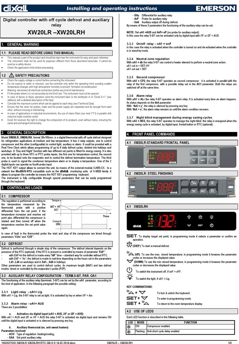
Emerson Dixell XR70CHC Wiring diagram

Emerson

Emerson Dixell XR70CHC Wiring diagram

Emerson EXD-HP1/2 User manual

Emerson

Emerson EXD-HP1/2 User manual

Emerson Dixell XM660K Wiring diagram

Emerson

Emerson Dixell XM660K Wiring diagram

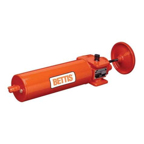
Emerson Bettis G Series User manual

Emerson

Emerson Bettis G Series User manual

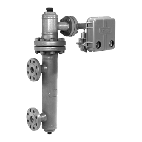
Emerson Level-Trol 2500 Series User manual

Emerson

Emerson Level-Trol 2500 Series User manual

Emerson 6351F User manual

Emerson

Emerson 6351F User manual

Emerson Fisher FIELDVUE DVC5000 Configuration guide

Emerson

Emerson Fisher FIELDVUE DVC5000 Configuration guide

Emerson Fisher 3025 User manual

Emerson

Emerson Fisher 3025 User manual

Emerson EC20 Series User manual

Emerson

Emerson EC20 Series User manual

Emerson Fisher 67C Series User manual

Emerson

Emerson Fisher 67C Series User manual

Emerson Bettis SCE300 User manual

Emerson

Emerson Bettis SCE300 User manual

Emerson FB3000 User manual

Emerson

Emerson FB3000 User manual

Emerson Fisher 656 User manual

Emerson

Emerson Fisher 656 User manual

Emerson Copeland XC643 User guide

Emerson

Emerson Copeland XC643 User guide

Emerson Bettis EHO User manual

Emerson

Emerson Bettis EHO User manual

Emerson Bettis G2XXX M11 series Operating instructions

Emerson

Emerson Bettis G2XXX M11 series Operating instructions

Emerson Fisher HSR Assembly instructions

Emerson

Emerson Fisher HSR Assembly instructions

Emerson Fisher 667 30 User manual

Emerson

Emerson Fisher 667 30 User manual

Emerson Liebert OpenComms EM User manual

Emerson

Emerson Liebert OpenComms EM User manual

Emerson Fisher Type 667 size 80 Manual

Emerson

Emerson Fisher Type 667 size 80 Manual

Emerson Hytork XL26 Instruction manual

Emerson

Emerson Hytork XL26 Instruction manual

Emerson White-Rodgers 11B79-3 User manual

Emerson

Emerson White-Rodgers 11B79-3 User manual

Emerson Copeland Site Supervisor Controller User manual

Emerson

Emerson Copeland Site Supervisor Controller User manual

Popular Controllers manuals by other brands

FIBARO SWIPE FGGC-001 user manual

FIBARO

FIBARO SWIPE FGGC-001 user manual

Eurotherm Invensys Mini8 user manual

Eurotherm

Eurotherm Invensys Mini8 user manual

GCE ECOSAVER+ operating instructions

GCE

GCE ECOSAVER+ operating instructions

Advanced Electronic Applications PK-88 operating manual

Advanced Electronic Applications

Advanced Electronic Applications PK-88 operating manual

Carel uChiller UCHBP00000190 user manual

Carel

Carel uChiller UCHBP00000190 user manual

Hubbell Reversing-Plugging Control 4010 Specifications

Hubbell

Hubbell Reversing-Plugging Control 4010 Specifications

ABB ControlMaster CM10 manual

ABB

ABB ControlMaster CM10 manual

MPPT ML2420 user manual

MPPT

MPPT ML2420 user manual

AVIRE Memco Panachrome+ installation guide

AVIRE

AVIRE Memco Panachrome+ installation guide

Mitsubishi AJ65BT-R2N-U-HW user manual

Mitsubishi

Mitsubishi AJ65BT-R2N-U-HW user manual

Madas FRG-RG/2MCSH manual

Madas

Madas FRG-RG/2MCSH manual

Sharp Blue Treak LH75400 user guide

Sharp

Sharp Blue Treak LH75400 user guide

PENKO 1020 Series manual

PENKO

PENKO 1020 Series manual

Azbil Infilex ZM WY5322 Specifications & instructions

Azbil

Azbil Infilex ZM WY5322 Specifications & instructions

Vimar by-me 01850.2 instruction sheet

Vimar

Vimar by-me 01850.2 instruction sheet

Boomerang Side Car operating instructions

Boomerang

Boomerang Side Car operating instructions

Siemens SIRIUS 3RW40 operating instructions

Siemens

Siemens SIRIUS 3RW40 operating instructions

Hitachi HCWA21NEWH Installation and operation manual

Hitachi

Hitachi HCWA21NEWH Installation and operation manual

manuals.online logo
manuals.online logoBrands
  • About & Mission
  • Contact us
  • Privacy Policy
  • Terms and Conditions

Copyright 2025 Manuals.Online. All Rights Reserved.