manuals.online logo
Brands
  1. Home
  2. •
  3. Brands
  4. •
  5. Emerson
  6. •
  7. Controllers
  8. •
  9. Emerson 6351F User manual

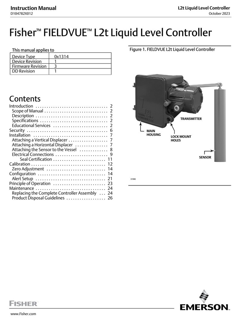
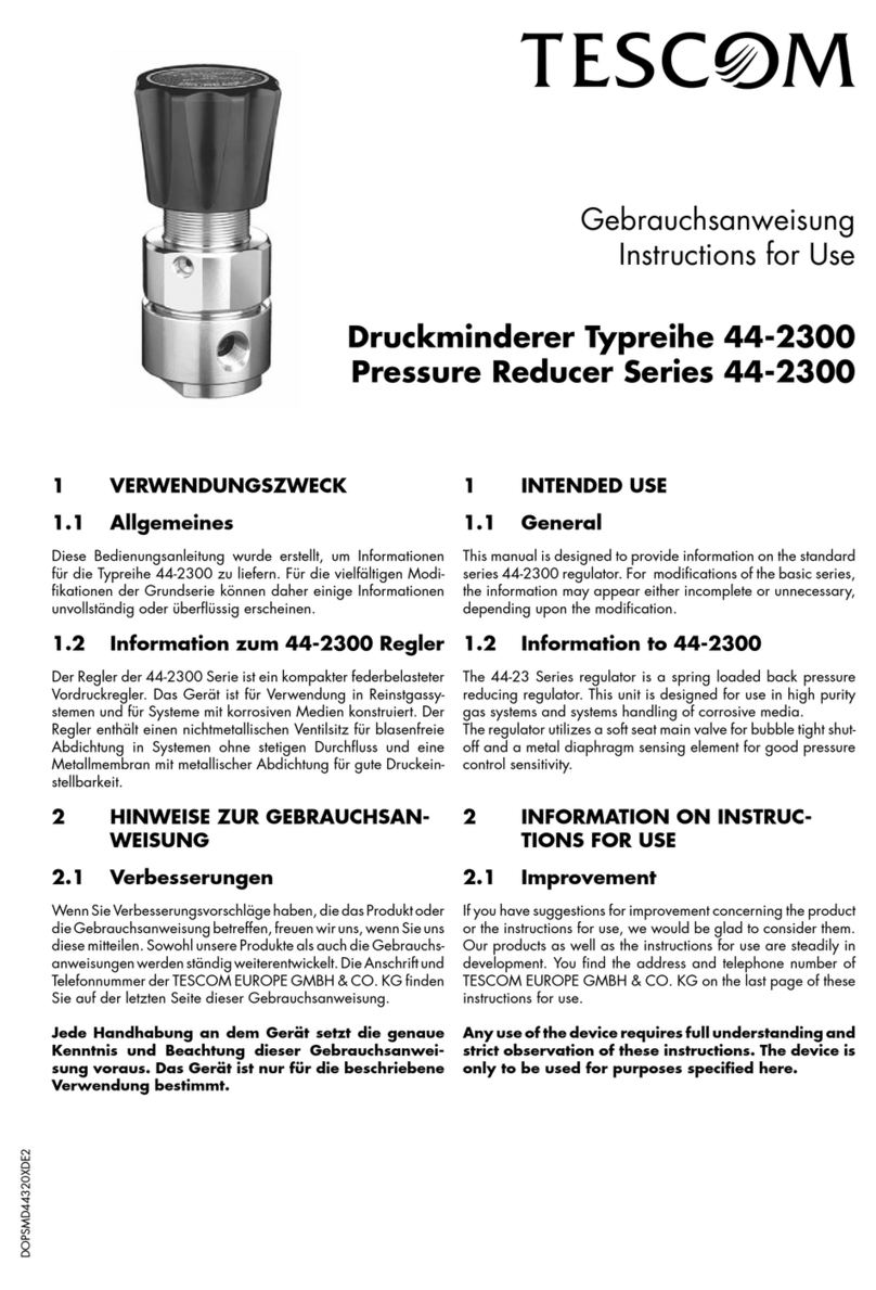
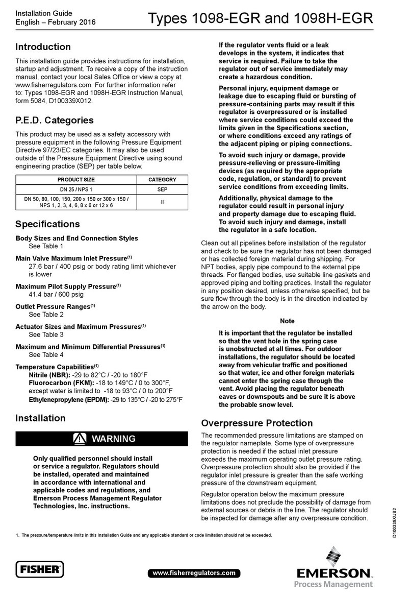
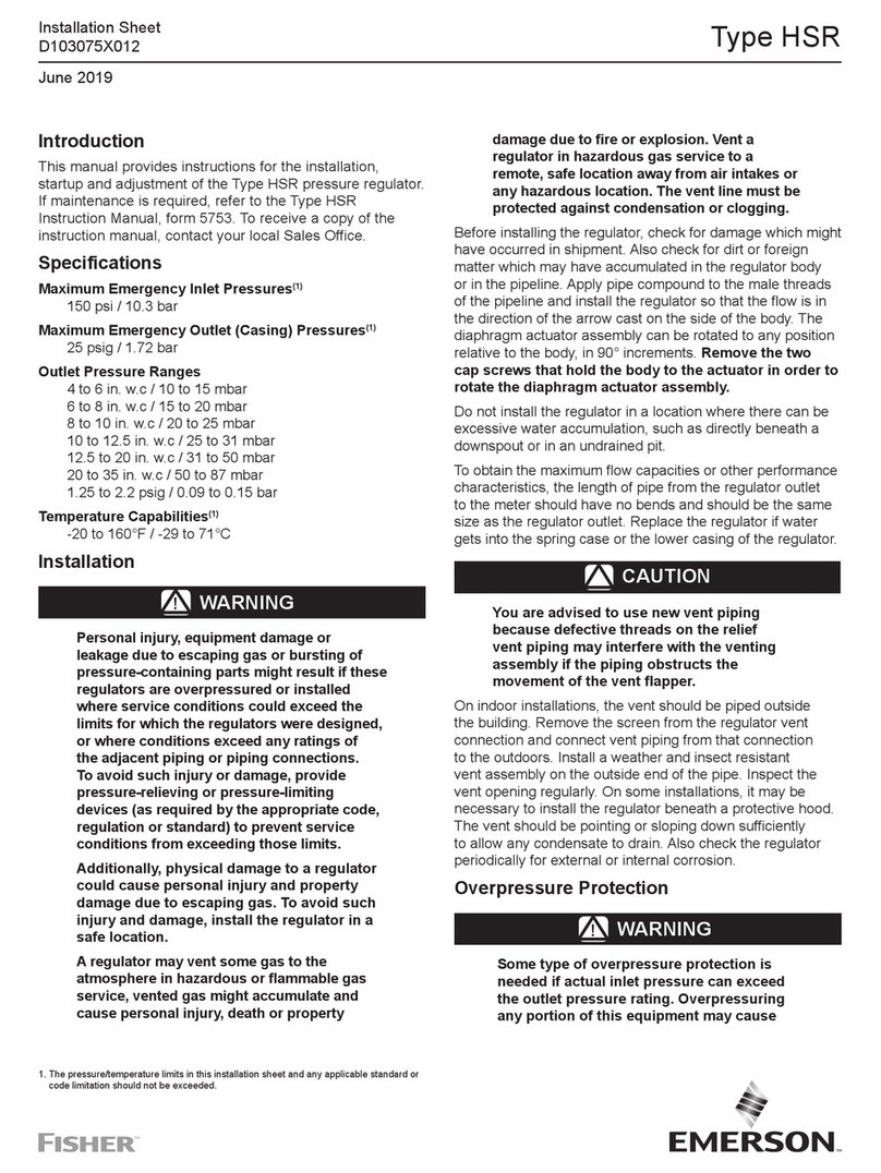
Emerson 6351F User manual

6350 Series
D100178XENG
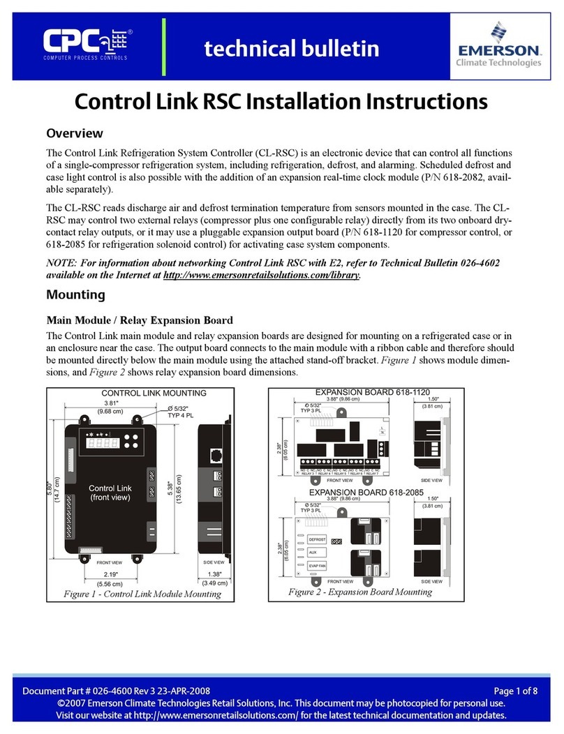
Installation Guide
English – May 2002
www.FISHERregulators.com
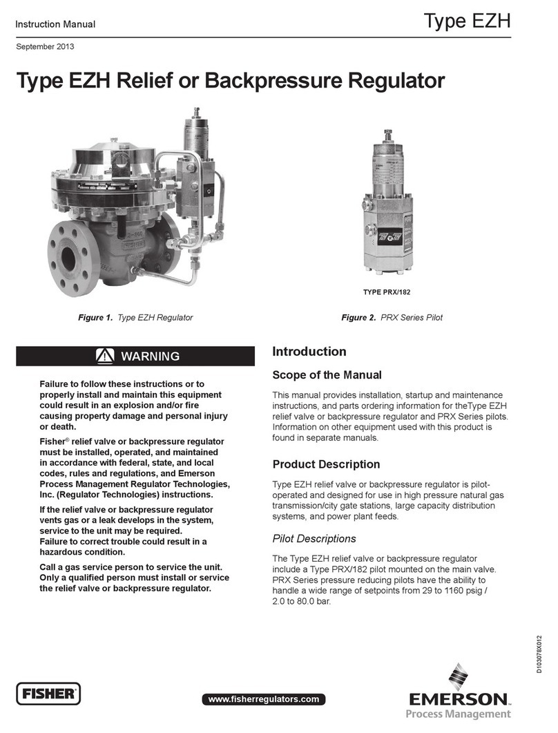
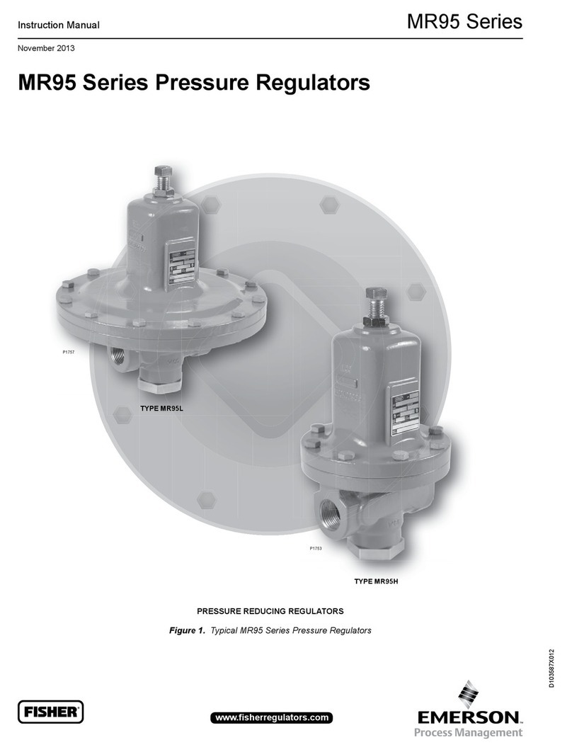
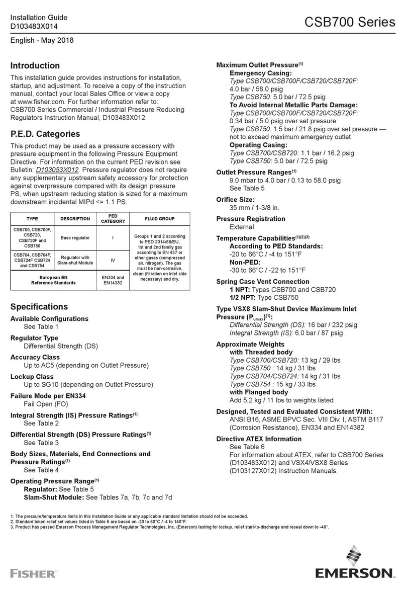
Introduction
This installation guide provides instructions for installation,
startup, and adjustment. To receive a copy of the instruction
manual, contact your local Fisher Sales
Office or Sales Representative or view a copy at
www.FISHERregulators.com. For further information refer to:
Type 1098-EGR Instruction Manual, form 5084, D100339X012
Type 627F Instruction Manual, form 5282, D101545X012
(for Type 6351F only)
P.E.D. Categories
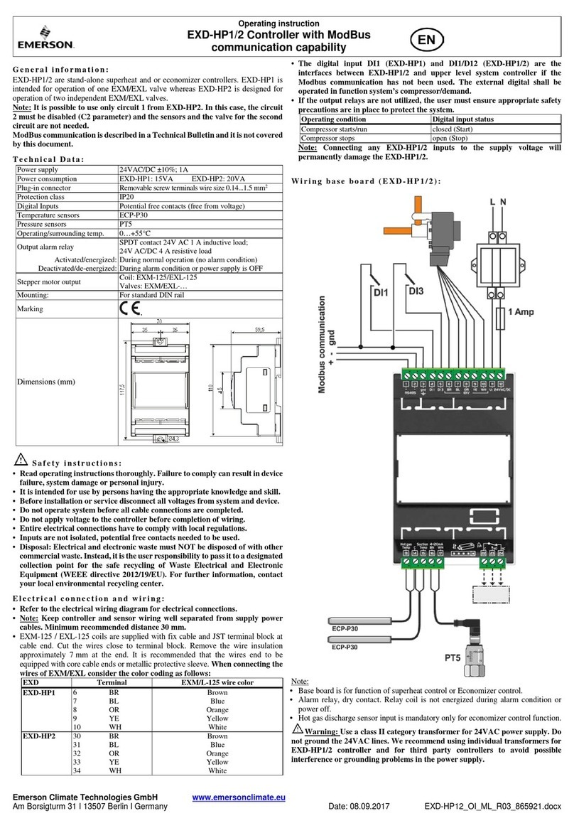
This product may be used as a safety accessory with
pressure equipment in the following Pressure Equipment
Directive 97/23/EC categories. It may also be used out-
side of the Pressure Equipment Directive using sound
engineering practice (SEP) per table below.
EZISTCUDORPSEIROGETACEPYTDIULF
)hcni-4/1(6NDPES1
Specifications
Available Configurations
6351: Set pressures – 0,21 to 6,9 bar (3 to 100
psig). This pilot has an unbalanced valve plug
design and fixed restriction.
6351F: Set pressures – 0,34 to 6,9 bar (5 to 100
psig). This pilot has an unbalanced valve plug
design and standard gain restriction. This pilot is
used with the Type 627F main valve.
6352: Set pressures – 5 mbar to 0,69 bar (2-
inches w.c. to 10 psig). This pilot has a balanced
valve plug design and a standard gain restriction.(1)
6353: Set pressures – 0,21 to 6,9 bar (3 to 100
psig). This pilot has a balanced valve plug design
and a standard gain restriction.(1)
6354L: Set pressures – 5,9 to 13,8 bar (85 to 200
psig). This pilot has a balanced valve plug design
and a standard gain restriction.(1)
6354M: Set pressures – 12,1 to 15,2 bar (175 to
220 psig). This pilot has a balanced valve plug
design and a standard gain restriction.(1)
6354H: Set pressures – 13,8 to 20,7 bar (200 to
300 psig). This pilot has a balanced valve plug
design and a standard gain restriction.(1)
Maximum Inlet Pressure(2)
41 bar (600 psig)
Maximum Outlet Pressure(2)
6351, 6351F: 10,3 bar (150 psig)
6352: 3,4 bar (50 psig)
6353: bar (150 psig)
6354L, 6354M, 6354H: 24,8 bar (360 psig)
Outlet Pressure Ranges
See table 1
Proof Test Pressure
All Pressure Retaining Components have been
proof tested per Directive 97/23/EC - Annex 1,
Section 7.4
Temperature Capabilities
Nitrile/Neoprene:
-40 to 82°C (-40 to 180°F)
Fluoroelastomer:
-18 to 149°C (0 to 300°F) hot
water limited to 82°C (180°F)
Installation
Only qualified personnel should install or service
a regulator. Regulators should be installed, oper-
ated, and maintained in accordance with interna-
tional and applicable codes and regulations, and
Fisher instructions.
If the regulator vents fluid or a leak develops in
the system, it indicates that service is required.
Failure to take the regulator out of service imme-
diately may create a hazardous condition.
Personal injury, equipment damage, or leakage
due to escaping fluid or bursting of pressure-con-
taining parts may result if this regulator is over-
pressured or is installed where service condi-
tions could exceed the limits given in the Specifi-
cations section, or where conditions exceed any
ratings of the adjacent piping or piping connec-
tions.
To avoid such injury or damage, provide pressure-
relieving or pressure-limiting devices (as required
by the appropriate code, regulation, or standard)
to prevent service conditions from exceeding lim-
its.
Additionally, physical damage to the regulator
could result in personal injury and property dam-
age due to escaping fluid. To avoid such injury
and damage, install the regulator in a safe loca-
tion.
1. Optional low gain restriction for liquid service and/or broader proportional bands or
high gain restriciton for narrower proportional bands (such as low-differential boiler
fuel service).
2. The pressure/temperature limits in this installation guide and any applicable
standard or code limitation should not be exceeded.
EPYTTOLIPEGNARERUSSERP)LORTNOC(TELTUO
1536
rab4,1ot12,0
rab4,2ot43,0
rab9,6ot4,2
)gisp02ot3(
)gisp53ot5(
)gisp001ot53(
F1536 rab4,2ot43,0
rab9,6ot4,2
)gisp53ot5(
)gisp001ot53(
2536 rabm041ot5
rab96,0ot41,0
)gisp2ot.c.wsehcni-2(
)gisp01ot2(
3536 rab8,2ot12,0
rab9,6ot4,2
)gisp04ot3(
)gisp001ot53(
L4536
)1(
M4536
)2(
H4536
rab8,31ot9,5
rab2,51ot1,21
rab7,02ot8,31
)gisp002ot58(
)gisp022ot571(
)gisp003ot002(
.retimilmgarhpaidtuohtiW.1
.retimilmgarhpaidhtiW.2
Table 1. Outlet Pressure Ranges
6350 Series
2
34A6635
32A6985
Clean out all pipelines before installation of the regulator
and check to be sure the regulator has not been damaged or
has collected foreign material during shipping. For NPT
bodies, apply pipe compound to the male pipe threads. For
flanged bodies, use suitable line gaskets and approved
piping and bolting practices. Install the regulator in any
position desired, unless otherwise specified, but be sure
flow through the body is in the direction indicated by the arrow
on the body.
Note
It is important that the regulator be installed so that
the vent hole in the spring case is unobstructed at
all times. For outdoor installations, the regulator
should be located away from vehicular traffic and
positioned so that water, ice, and other foreign
materials cannot enter the spring case through the
vent. Avoid placing the regulator beneath eaves or
downspouts, and be sure it is above the probable
snow level.
Overpressure Protection
The recommended pressure limitations are stamped on
the regulator nameplate. Some type of overpressure
protection is needed if the actual inlet pressure exceeds the
maximum operating outlet pressure rating. Overpressure
protection should also be provided if the regulator inlet
pressure is greater than the safe working pressure of the
downstream equipment.
Regulator operation below the maximum pressure limitations
does not preclude the possibility of damage from external
sources or debris in the line. The regulator should be inspected
for damage after any overpressure condition.
Startup
The regulator is factory set at approximately the midpoint of
the spring range or the pressure requested, so an initial
adjustment may be required to give the desired results. With
proper installation completed and relief valves properly
adjusted, slowly open the upstream and downstream shutoff
valves.
Adjustment
To change the outlet pressure, remove the closing cap or
loosen the locknut and turn the adjusting screw clockwise
to increase outlet pressure or counterclockwise to decrease
pressure. Monitor the outlet pressure with a test gauge
during the adjustment. Replace the closing cap or tighten
the locknut to maintain the desired setting.
Taking Out of Service (Shutdown)
To avoid personal injury resulting from sudden
release of pressure, isolate the regulator from all
pressure before attempting disassembly.
Figure 1. Type 6351 Pilot Assembly
DETAIL OF SPRING CASE AND VENT
FOR TYPE 661 MOUNTING
COMPLETE PILOT SHOWING
STANDARD SPRING CASE CONSTRUCTION
Type 6351 Parts List
Key Description
1 Body Assembly
2 Bonnet
3 Body Plug Assembly
4 Inner Valve Assembly
6 Valve Spring
7 Diaphragm Assembly
8 Upper Spring Seat
9 Control Spring
10 Adjusting Screw
11 Locknut
12 Machine Screw
22 Pipe Nipple
24 P590 Series Filter
35 Vent Assembly
42 Relief Valve Assembly
6350 Series
3
32B3797-D
35A6236
35A8889
Figure 2. Type 6351F Assembly
Type 6351F Parts List
Key Description
1 Body Assembly
2 Spring Case
3 Body Plug
4 Inner Valve Assembly
6 Valve Spring
7 Diaphragm Assembly
8 Upper Spring Seat
9 Control Spring
10 Adjusting Screw
11 Locknut
22 Pipe Nipple
23 Body Plug Gasket
24 P590 Filter (Optional)
28 Closing Cap
35 Vent Assembly
44 Restriction
Figure 3. Type 6352 Through 6354H Pilot Assemblies
DETAIL OF TYPE 6354M OR 6354H PILOT
COMPLETE TYPE 6352, 6353, OR 6354L PILOT
Types 6352, 6353, 6354L,
6354M, and 6354H Parts List
Key Description
1 Pilot Body
2 Spring Case
3 Body Plug
4 Valve Plug and Stem Assembly
5 Diaphragm Assembly
6 Control Spring
7 Spring Seat
8 Stem Guide
9 Adjusting Screw
10 Locknut
11 Closing Cap
12 Body Plug Gasket / O-ring
13 Vent Assembly
14 Machine Screw
15 Relief Valve Assembly
16 Bellows Assembly
17 O-ring
19 Filter
20 Closing Cap Gasket
21 Pipe Nipple
22 Restriction
23 Diaphragm Limiter
6350 Series
For information, contact Fisher Controls, International:
Within USA (800) 588-5853 – Outside USA (972) 542-0132
Italy – (39) 051-4190-606
Singapore – (65) 770-8320
Mexico – (52) 57-28-0888
©Fisher Controls International, Inc., 2002; All Rights Reserved
Fisher and Fisher Regulators are marks owned by Fisher Controls International, Inc. The Emerson logo is a trade mark and service mark of Emerson Electric Co.
All other marks are the property of their respective owners.
The contents of this publication are presented for informational purposes only, and while every effort has been made to ensure their accuracy, they are not to be construed as warranties or guarantees, express
or implied, regarding the products or services described herein or their use or applicability. We reserve the right to modify or improve the designs or specifications of such products at any time without notice.
Printed in U.S.A. www.FISHERregulators.com
A7008
Figure 4. Standard P590 Series Filter Assembly
P590 Series Parts List
Key Description
1 Filter Body
2 Filter Element
3 Filter Head
4 Machine Screw
5 Washer
6 Spring Washer
7 Gasket

This manual suits for next models

7

Other Emerson Controllers manuals

Emerson Bettis RTS User manual

Emerson

Emerson Bettis RTS User manual

Emerson Tartarini B/240-FS Series User manual

Emerson

Emerson Tartarini B/240-FS Series User manual

Emerson Dixell XR75CX Series User manual

Emerson

Emerson Dixell XR75CX Series User manual

Emerson Fisher FIELDVUE DVC2000 User manual

Emerson

Emerson Fisher FIELDVUE DVC2000 User manual

Emerson EZH Series User manual

Emerson

Emerson EZH Series User manual

Emerson ECD-002 User manual

Emerson

Emerson ECD-002 User manual

Emerson Fisher LS200 Series User manual

Emerson

Emerson Fisher LS200 Series User manual

Emerson PMAC II Solo User manual

Emerson

Emerson PMAC II Solo User manual

Emerson Fisher 1098-EGR User manual

Emerson

Emerson Fisher 1098-EGR User manual

Emerson AVENTICS Sentronic D User manual

Emerson

Emerson AVENTICS Sentronic D User manual

Emerson Fisher 133H User manual

Emerson

Emerson Fisher 133H User manual

Emerson Fisher 4194S User manual

Emerson

Emerson Fisher 4194S User manual

Emerson CASH VALVE A-32 User manual

Emerson

Emerson CASH VALVE A-32 User manual

Emerson Dixell XR20-30-60-70T User manual

Emerson

Emerson Dixell XR20-30-60-70T User manual

Emerson 99 User manual

Emerson

Emerson 99 User manual

Emerson Fisher Y692 User manual

Emerson

Emerson Fisher Y692 User manual

Emerson Fisher 627 Series User manual

Emerson

Emerson Fisher 627 Series User manual

Emerson EIM 2000 Series Manual

Emerson

Emerson EIM 2000 Series Manual

Emerson Fisher 92C User manual

Emerson

Emerson Fisher 92C User manual

Emerson Bettis GVO LP DA User manual

Emerson

Emerson Bettis GVO LP DA User manual

Emerson PACSystems RX3i IC695CPE330 User manual

Emerson

Emerson PACSystems RX3i IC695CPE330 User manual

Emerson XEV EX48 User manual

Emerson

Emerson XEV EX48 User manual

Emerson Keystone EPI2 63 User manual

Emerson

Emerson Keystone EPI2 63 User manual

Emerson Rosemount 3490 Series User manual

Emerson

Emerson Rosemount 3490 Series User manual

Popular Controllers manuals by other brands

Projecta INTELLI-START IS3000 instructions

Projecta

Projecta INTELLI-START IS3000 instructions

Regin SPINN/D instructions

Regin

Regin SPINN/D instructions

Siemens SINUMERIK 802D sl Function manual

Siemens

Siemens SINUMERIK 802D sl Function manual

IAI ROBO CYLINDER RCM-P operating manual

IAI

IAI ROBO CYLINDER RCM-P operating manual

HP 615418-B21 specification

HP

HP 615418-B21 specification

Microchip Technology dsPIC30F Guide

Microchip Technology

Microchip Technology dsPIC30F Guide

LINK-MI LM-R90U user manual

LINK-MI

LINK-MI LM-R90U user manual

Allen-Bradley powerflex 700 installation instructions

Allen-Bradley

Allen-Bradley powerflex 700 installation instructions

ABB i-bus KNX product manual

ABB

ABB i-bus KNX product manual

A+ Corporation Sampling Experts Genie GHR product manual

A+ Corporation

A+ Corporation Sampling Experts Genie GHR product manual

Contemporary Research ICC1 product manual

Contemporary Research

Contemporary Research ICC1 product manual

Elmes Electronic STM-2K quick start guide

Elmes Electronic

Elmes Electronic STM-2K quick start guide

Rigel usb-nSTEP instructions

Rigel

Rigel usb-nSTEP instructions

Murphy MX4 Series Installation and operation manual

Murphy

Murphy MX4 Series Installation and operation manual

Precision Digital Corporation PROVU PD6310 instruction manual

Precision Digital Corporation

Precision Digital Corporation PROVU PD6310 instruction manual

Ascon tecnologic KX5P Engineering manual

Ascon tecnologic

Ascon tecnologic KX5P Engineering manual

elero AstroTec 28 060.0001 operating instructions

elero

elero AstroTec 28 060.0001 operating instructions

Anderson EVA2 Series Installation and operating instructions

Anderson

Anderson EVA2 Series Installation and operating instructions

manuals.online logo
manuals.online logoBrands
  • About & Mission
  • Contact us
  • Privacy Policy
  • Terms and Conditions

Copyright 2025 Manuals.Online. All Rights Reserved.