4
Rosemount Manifolds August 2016
EmersonProcess.com/Rosemount
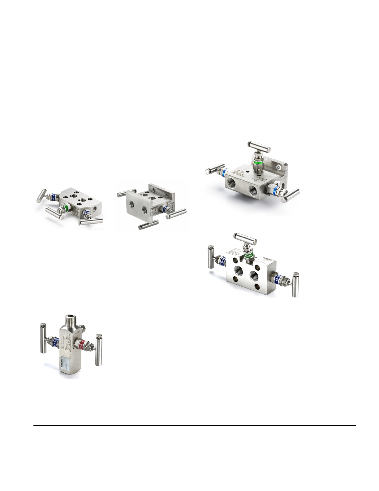
Five-valve
The 5-valve configuration is available on Rosemount 305 and 304
Manifolds for use with differential pressure and multivariable
transmitters. Two isolate valves provide instrument isolation and
one equalize valve is positioned between the high and low process
connections. In addition, two drain/vent valves allow for controlled
venting, 100 percent capture of vented or drained process, and
simplified in-process calibration capability.
Rosemount 305 Manifolds and 304 (Wafer)
Five-valve natural gas
The 5-valve natural gas configuration is available on the
Rosemount 305 and 304 Manifolds for use with differential
pressure and multivariable transmitters. Two isolate valves provide
instrument isolation and a single drain/vent valve allows for
controlled venting, 100 percent capture of vented or drained
process, and simplified in-process calibration capability. In
addition, two equalize valves provide extra protection from
leaking to ensure DP signal integrity.
“NG” option includes wide handle pattern and soft seats for ease
of use as well as a larger bore to reduce plugging
Rosemount 305 Manifolds and 304 (Traditional)
Note
Vent ports receive plastic caps to protect threaded
connections unless otherwise noted.
Note
Plugged connections receive 1/4-in. NPT plugs unless
otherwise noted.
Ordering information
Rosemount Manifolds can be ordered as a stand-alone product or
as an integrated assembly attached to a transmitter.
Stand-alone manifold
1. Reference the “Selection guide” on page 2 for assistance on
choosing the type of manifold.
2. Specify a completed model number by referencing the
applicable ordering table for the selected manifold type:
Rosemount 305 Integral Manifold, see page 5.
Rosemount 306 In-line Manifold, see page 7.
Rosemount 304 Conventional Manifold, see page 9.
Transmitter/manifold assembly
1. Specify a completed Rosemount transmitter model number
by referencing the applicable product data sheet.
2. Specify a completed manifold model number by referencing
the applicable ordering table for the selected manifold type:
Rosemount 305 Integral Manifold, see page 5.
Rosemount 306 In-line Manifold, see page 7
Rosemount 304 Conventional Manifold, see page 9.
3. Verify the transmitter model number contains the correct
“Process Connection” code or “Manifold Option” code for
the desired transmitter manifold assembly (see Table 1).
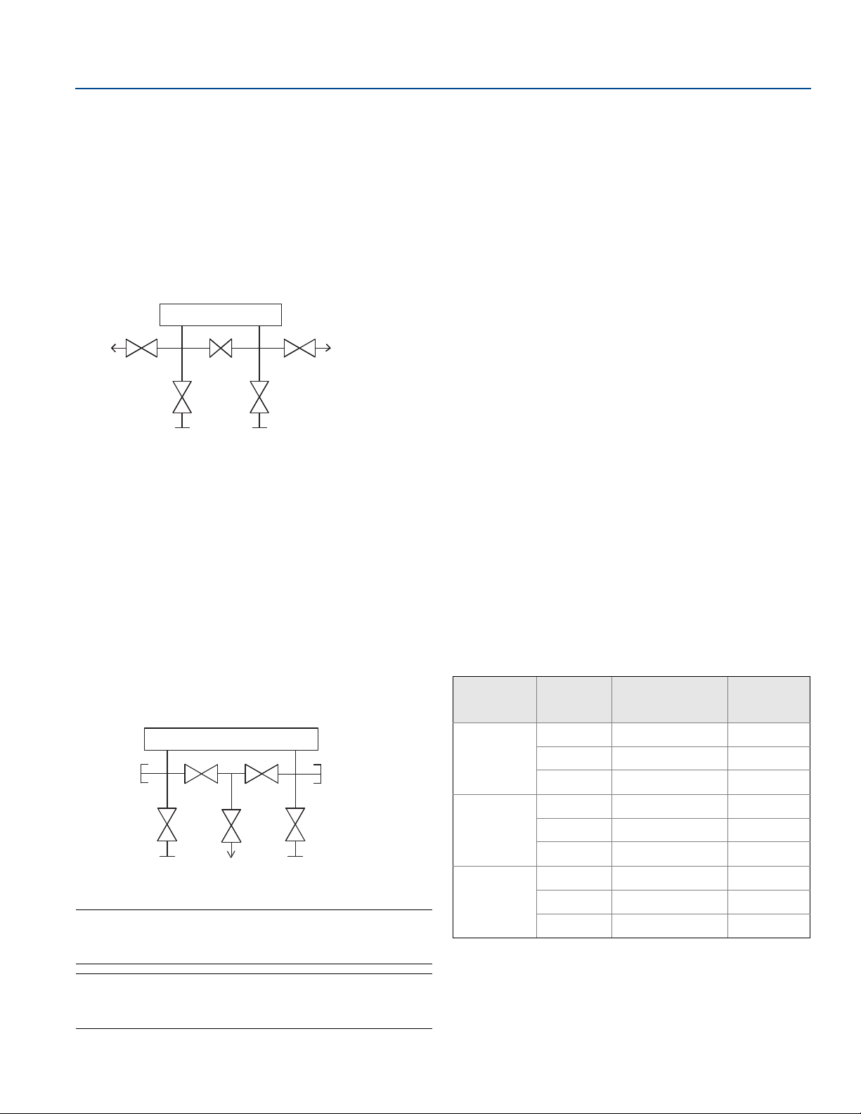
Transmitter
Vent
Vent
Equalize
Process
IsolateIsolate
Transmitter
Equalize
Process
Equalize
Process
IsolateIsolate
(plugged)(plugged)
Vent
(closed)
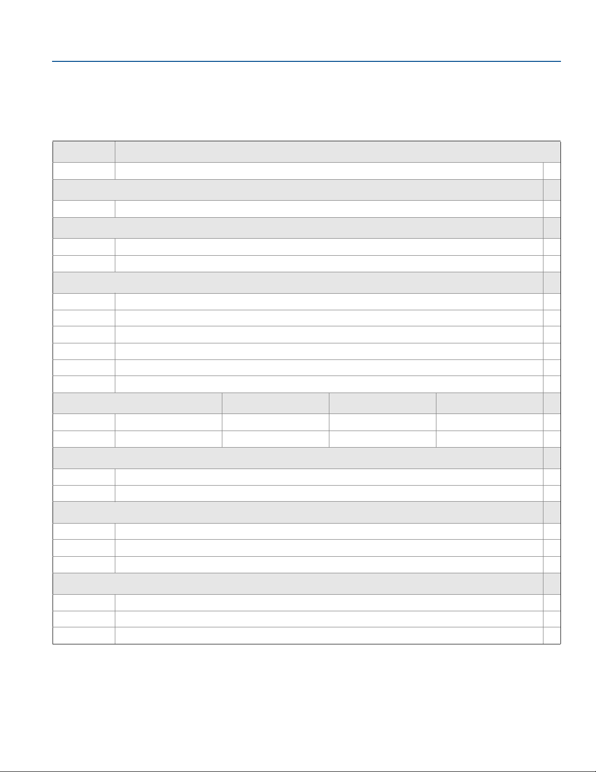
Table 1. Ordering Codes for a Transmitter/Manifold
Assembly
Transmitter Manifold Process
connection code
“Manifold”
option code
Rosemount
3051S
305 A11 N/A
306 A11 N/A
304 A12 N/A
Rosemount
3051/2051
305 N/A S5
306 N/A S5
304 N/A S6
Rosemount
2088
305 N/A N/A
306 N/A S5
304 N/A N/A