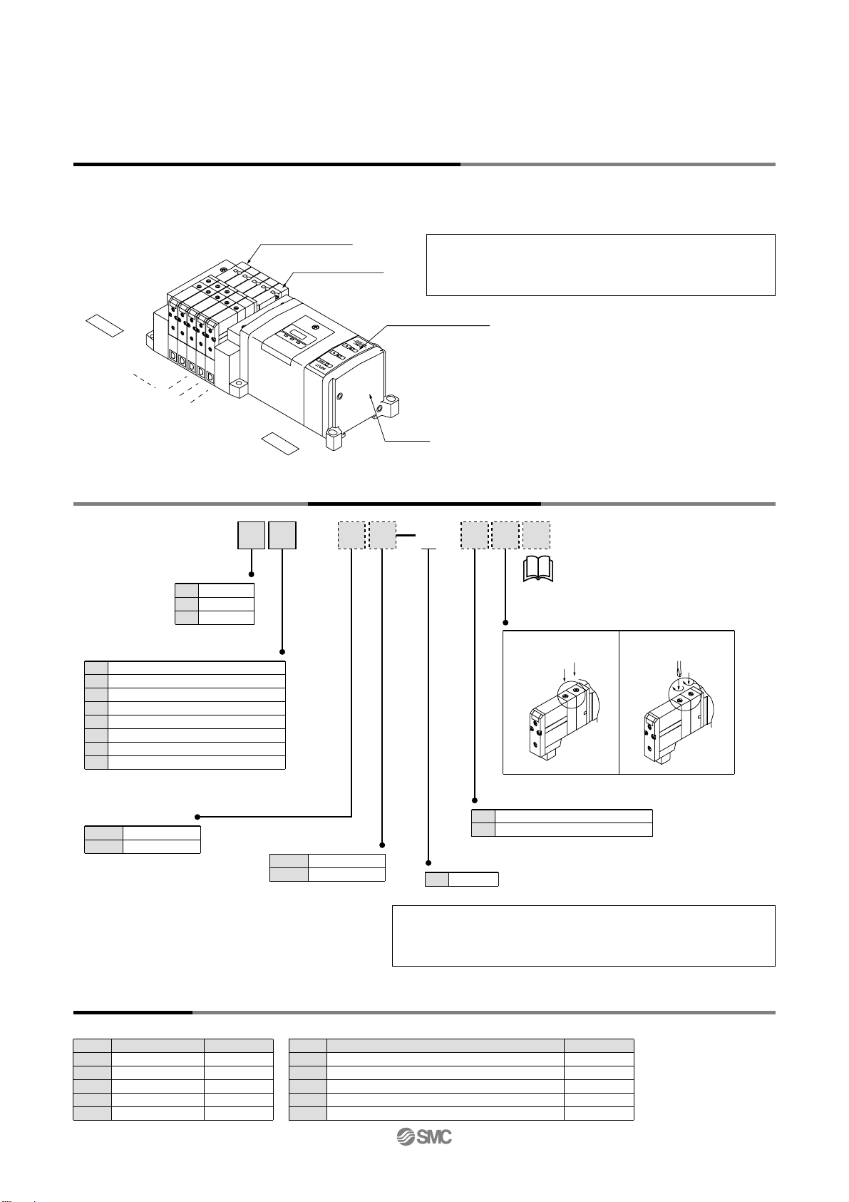
W10S1
1
2
3
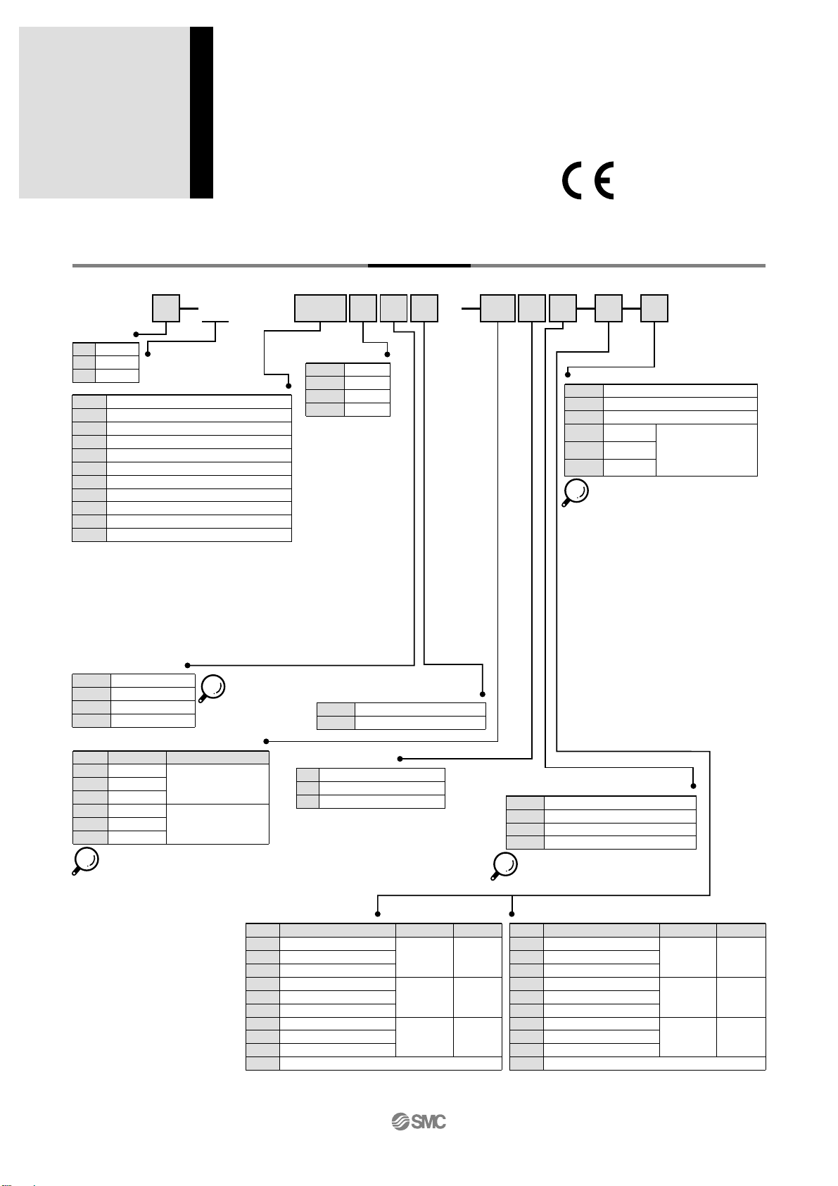
SV1000
SV2000
SV3000
Series
Stations
Note
Double wiring
specification Note 1)
Specified layout Note 2)
(Up to 32
solenoids possible.)
Symbol
02
16
02
20
No. of stations
2 stations
16 stations
2 stations
20 stations
• When an AS-i compatible SI unit is used, the
maximum numbers of solenoids are as follows:
8in/8out specification: Maximum 8 solenoids
4in/4out specification: Maximum 4 solenoids
Note 1) Double wiring specifica-
tion: Single, double, 3 po-
sition and 4 position sole-
noid valves can be used
on all manifold stations.
Use of a single solenoid
will result in an unused
control signal. If this is not
desired, order with a speci-
fied layout.
Note 2) Specified layout: Indicate
the wiring specification on
a manifold specification
sheet. (Note that double, 3
position and 4 position val-
ves cannot be used where
single solenoid wiring has
been specified.)
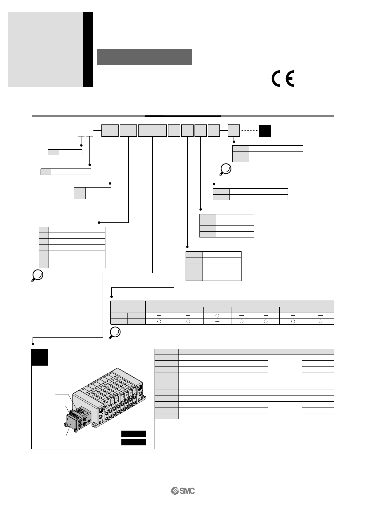
쎲Tie-rod Base
SS5V D1
Input block common
specification
+COM. or without input block
–COM.
-
N
A, B port size (Inch)
A, B port
Symbol
N1
N3
N7
N3
N7
N9
N7
N9
N11
M
With one-touch fitting for ø1/8"
With one-touch fitting for ø5/32"
With one-touch fitting for ø1/4"
With one-touch fitting for ø5/32"
With one-touch fitting for ø1/4"
With one-touch fitting for ø5/16"
With one-touch fitting for ø1/4"
With one-touch fitting for ø5/16"
With one-touch fitting for ø3/8"
A, B ports mixed
With one-touch
fitting for
ø5/16"
P, E port
Applicable series
SV1000
SV2000
SV3000
With one-touch
fitting for
ø3/8"
With one-touch
fitting for
ø3/8"
A, B port size (Metric)
A, B port
Symbol
C3
C4
C6
C4
C6
C8
C6
C8
C10
M
With one-touch fitting for ø3.2
With one-touch fitting for ø4
With one-touch fitting for ø6
With one-touch fitting for ø4
With one-touch fitting for ø6
With one-touch fitting for ø8
With one-touch fitting for ø6
With one-touch fitting for ø8
With one-touch fitting for ø10
A, B ports mixed
With one-touch
fitting for
ø8
P, E port
Applicable series
SV1000
SV2000
SV3000
With one-touch
fitting for
ø10
With one-touch
fitting for
ø12
SI unit
DeviceNet
PROFIBUS-DP
CC-Link
AS-i 8in/8out 31Slave Mode , 2 power supply system
AS-i 4in/4out 31Slave Mode , 2 power supply system
AS-i 8in/8out 31Slave Mode, 1 power supply system
AS-i 4in/4out 31Slave Mode, 1 power supply system
CANopen
ControlNet (IP40)
EtherNet/IP
Without SI unit, Without end plate
QW
NW
VW
TAW
TBW
TCW
TDW
YW
ZCN
ZEN
0
• Input blocks cannot be mounted without an SI unit.
• When the DIN rail is included without an SI unit, the DIN rail length will
accommodate an SI unit and one input block.
Note 1) There is a limit to the current supplied from an AS-i compatible SI unit,
1 power supply system specification to an input block or valve. For
details, refer to page 13.
Note 2) IP40 for the ControlNet compatible SI unit. (Manifold model no. is
“SS5V쏔-10S1ZCN쏔쏔쏔D”.)
Note 3) For SI unit part no., refer to page 3.
∗ In the case of a mixed specification (M), indicate separately on a manifold specification sheet.
∗ The port sizes for the X, PE ports of the external pilot specification (R, RS) are ø4 (metric), ø5/32" (inch) for the SV1000/2000 series
and ø6 (metric) and ø1/4" (inch) for the SV3000 series.
Input block stations
None
1 station
8 stations
-
1
8
Note) Without SI unit, the
symbol is "-".
When an AS-i
compatible SI unit is
used, there is a limit
to the maximum
number of stations.
For details, please
refer to page 13.
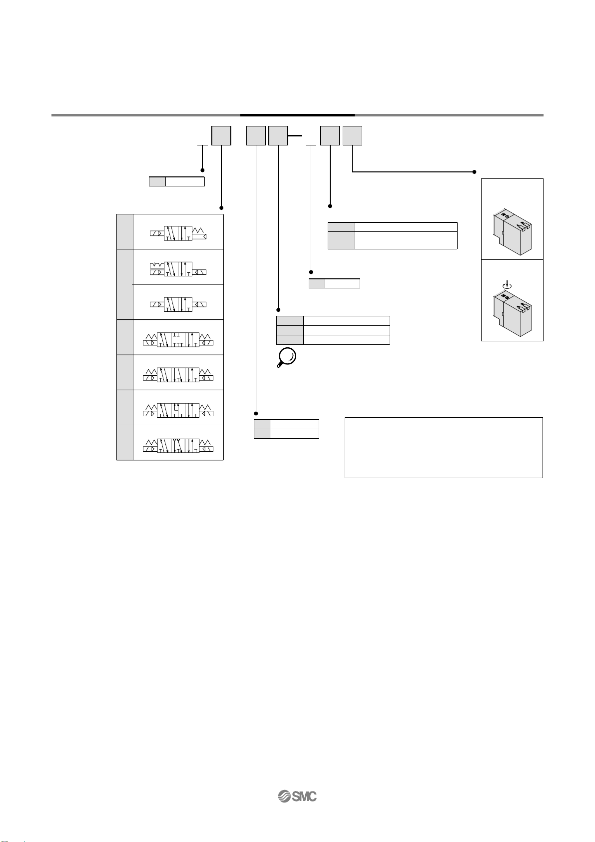
How to Order
EX250 Serial Wiring
With Input/Output Unit
Series SV
05 U
P, E port position
U
D
B
U side (2 to 10 stations)
D side (2 to 10 stations)
Both sides (2 to 20 stations)
3 stations
20 stations
When a longer DIN rail is
desired than the specified
stations.
(Specify a longer rail than
the standard length.)
Mounting
-
D
D0 Note)
D3
D20
Note) In the case of D0, only DIN rail
brackets are attached.
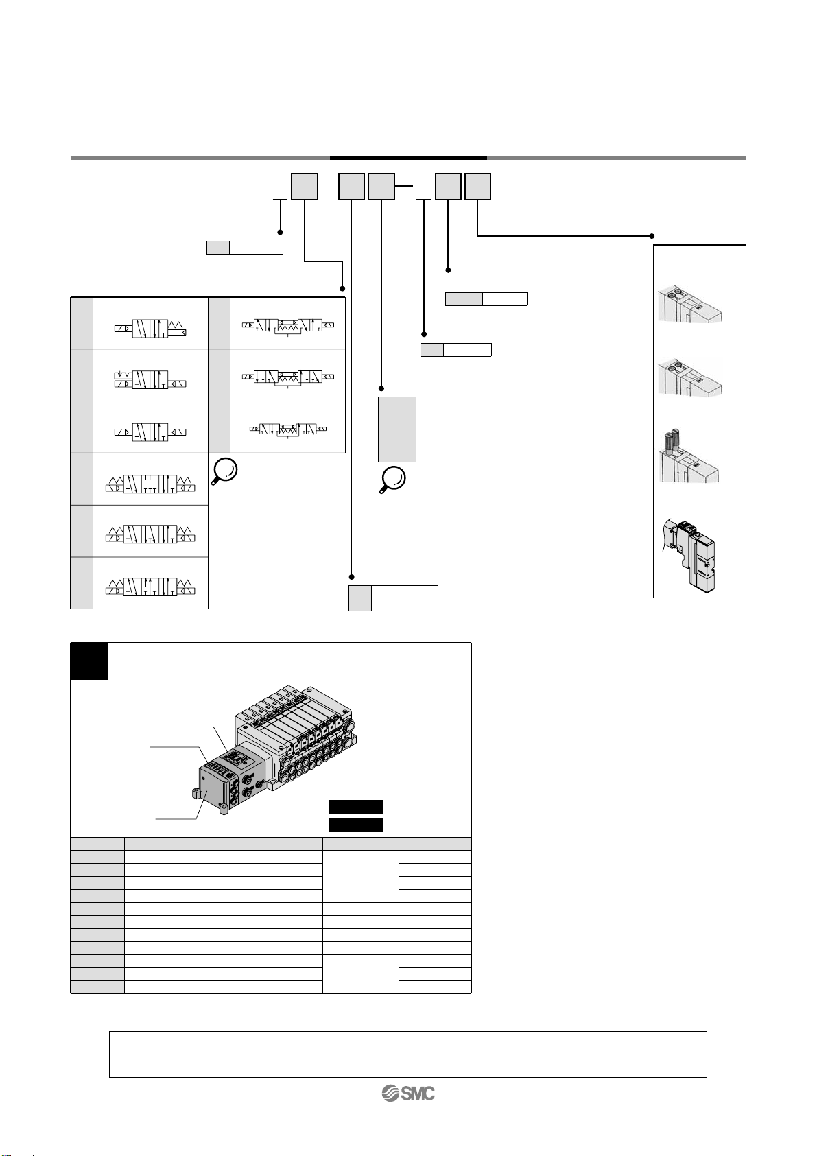
SUP/EXH block assembly specification
Internal pilot
Internal pilot, Built-in silencer
External pilot
External pilot, Built-in silencer
-
S Note)
R
RS Note)
Note) When the built-in silencer type is used,
keep the exhaust port away from direct
contact with water or other liquids.
Enclosure
IP67 specification
QW
Without input block
M12 2 inputs
M12 4 inputs
M8 4 inputs
Input block type
-
1
2
3
Note) Without SI
unit, the
symbol is "-".
Direct mounting
DIN rail mounting (with DIN rail)
DIN rail mounting (without DIN rail)
...
...
...
...
...
...
...
...
2