[SM-P00045-A/2] -3-
UNPACKING (Chapter 3.)
Bags containing solenoid valves should be opened only when you
are ready to connect the valves to the pipes immediately afterward.
yIf bags are opened before the valves are ready to be connected to
the pipes, the entry of foreign matter from the piping ports could
cause the solenoid valves to fail or malfunction.
INSTALLATION (Chapter 4.)
If you have to use the product under conditions that are different
from the specified conditions or if you intend to use the product for
a special application, be sure to consult us about the product
specifications before using the product.
ENVIRONMENT (Section 4.1)
a) In a dusty environment, foreign matter may enter even
through the exhaust port.
yForeign matter may go into the inside of a solenoid valve by the
direction of an exhaust port, which may cause inhalation of foreign
matter near the exhaust port. Attach a silencer to the exhaust port
or have the exhaust port face downward.
b) Keep the solenoid valve system dry. Take care to avoid direct
contact with dripping water or splashes of cutting oil.
yIf the solenoid valve system is wet by a direct contact with water or
cutting oil, an electrical leak or burnt solenoid coils may result.
Protect the solenoid valve system by using a cover or by installing
it inside a paneled casing. If the cylinder rod is splashed with
cutting oil, the oil may penetrate through the cylinder into the
secondary side piping of the solenoid valve. This must be
prevented to avoid malfunctions.
c) The coils will produce heat.
yParticularly if the solenoid valve system is installed in a control
board or if the solenoid coils need to be energized for a long time,
consider providing sufficient ventilation to release the heat. The
coils can get very hot.
yThe coil temperature may be raised with the ambient temperature
and/or energization time, thus pay sufficient attention when
touching the valves.
d) Do not use the solenoid valve system in an atmosphere that
includes a corrosive gas or solvent vapors.
yDo not use the solenoid valve system in an atmosphere that
includes a corrosive gas such as the sulfur dioxide gas or in an
atmosphere that includes solvent vapors.
e) Vibration resistance and shock resistance
yDo not subject the solenoid valve system to vibrations 50m/s2or
stronger or shocks 300m/s2or stronger.
f) Avoid using the solenoid valve system in a humid environment
because the humidity is likely to cause condensation with a
change in the temperature.
g) Do not use the normal type solenoid valves for an application
that requires conformity with explosion-proof specifications.
Choose explosion-proof solenoid valves instead.
h) The packing and gaskets may deteriorate sooner than usual if
used in an atmosphere with a higher than normal density of
ozone (for example, the atmosphere near a beach or in an area
with frequent thunderstorms).
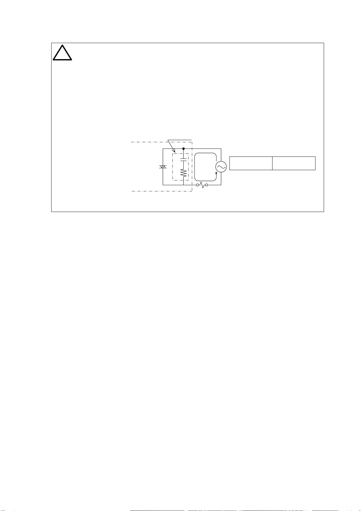
i)There is no resistance to surges caused by overvoltage from
switching and lightning transients(CE Marking :IEC61000-4-5).
Please take measures against surges on the equipment side.
!
WARNING :
!
CAUTION :
!
CAUTION :