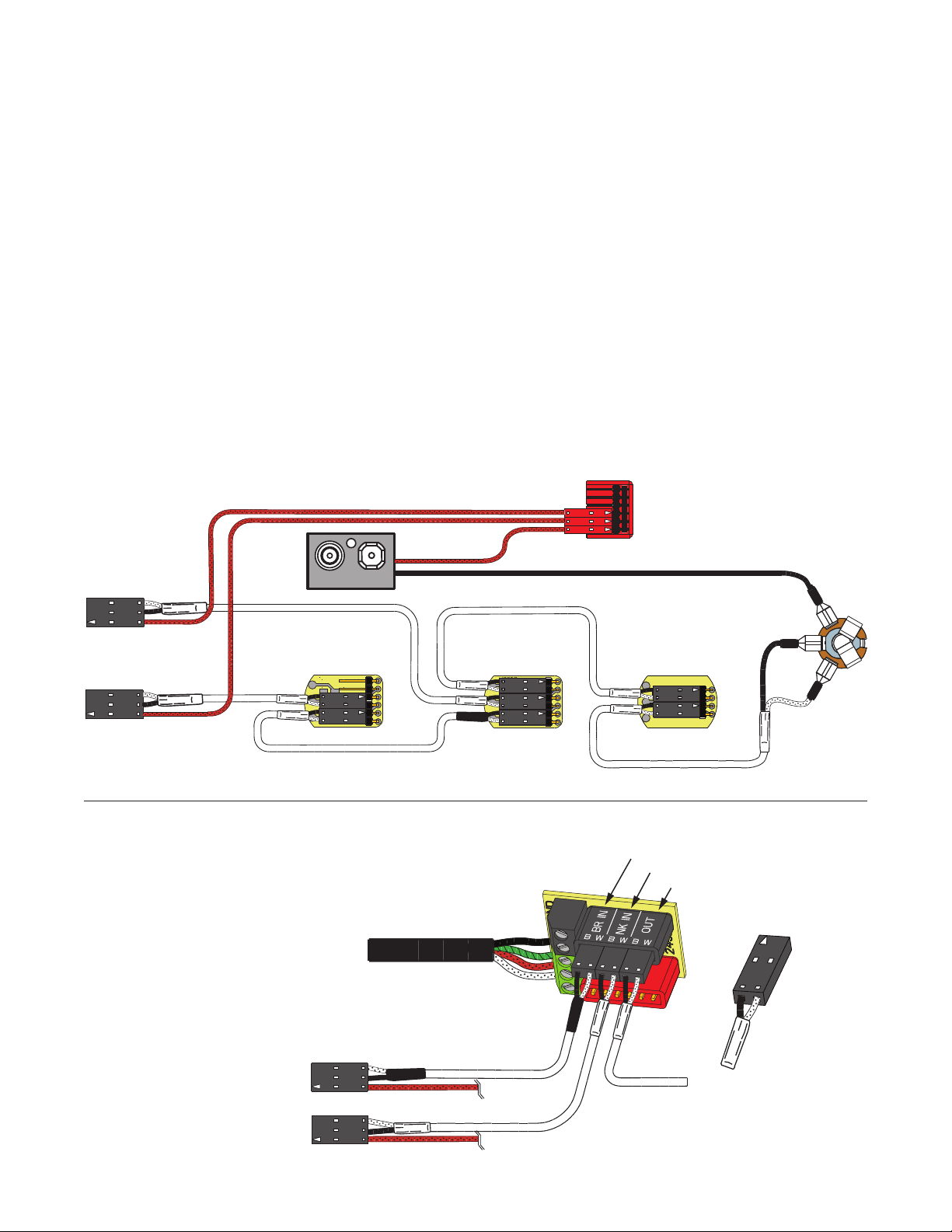
BRIDGE PICKUP INPUT
NECK PICKUP INPUT
OUTPUT
NECK PICKUP
BRIDGE PICKUP
TO SELECTION SWITCH
PLUG IN
LIKE THIS!
35 BASS Page 3
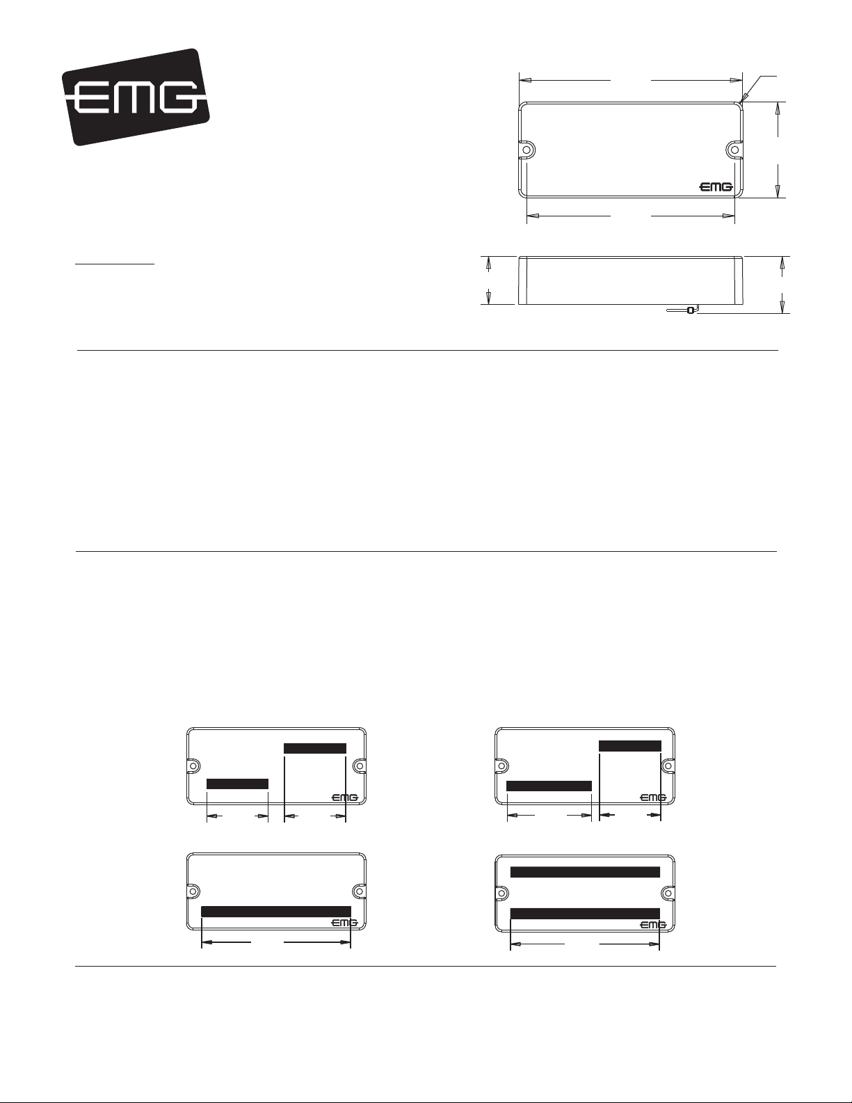
Installation Instructions:
EMG Models: 35P4, 35P4A (4-STRING)
35P5 (NARROW 5-STRING)
35J, 35JA (4-STRING OR NARROW 5-STRING)
VOLUME
B122rH
TONE
B124rH
VOLUME
B122rH
2 Pickups, 2 Volume controls and Master Tone, no selection switch
J-Bass Style wiring
Refer to Diagram #4
1) Install the Pickups and route the Pickup cables to the control cavity.
If the cables are too long, keep any excess under the pickup.
2) Mount the Volume and Tone controls into the body / pickguard.
Plug the Neck Pickup Cable onto the Neck Volume control.
Plug the Bridge Pickup Cable onto the Bridge Volume control.
3) Plug a coax cable from the Neck Volume control to the Bridge Volume
Control.
4) Plug a coax cable from the Bridge Volume control the Master Tone control.
5) Plug the output cable onto the Master Tone control and connect the output
wires to the output jack by pushing the connectors on as shown.
WHITE wire onto the TIP (T) contact,
BLACK wire onto the SLEEVE (S) contact
BLACK Battery Negative wire onto the RING (R) contact.
6) Plug the RED Wires of the pickups onto the V+ Supply Buss (RED Shroud)
along with the RED of the battery clip.
Extra pins on the V+ Supply Buss are for EMG Accessories.
7) Put the battery in the insulating foam piece provided and place it securely in the
control cavity.
We suggest that you plug in the instrument and test it before closing the
control cavity.
Diagram #4
Volume / Volume
Master Tone (Passive)
- 9V + OUTPUT
T
R
S
OUTPUT CABLE
NECK PICKUP
BRIDGE PICKUP
BR VOLUME
MASTER
TONE
NK VOLUME
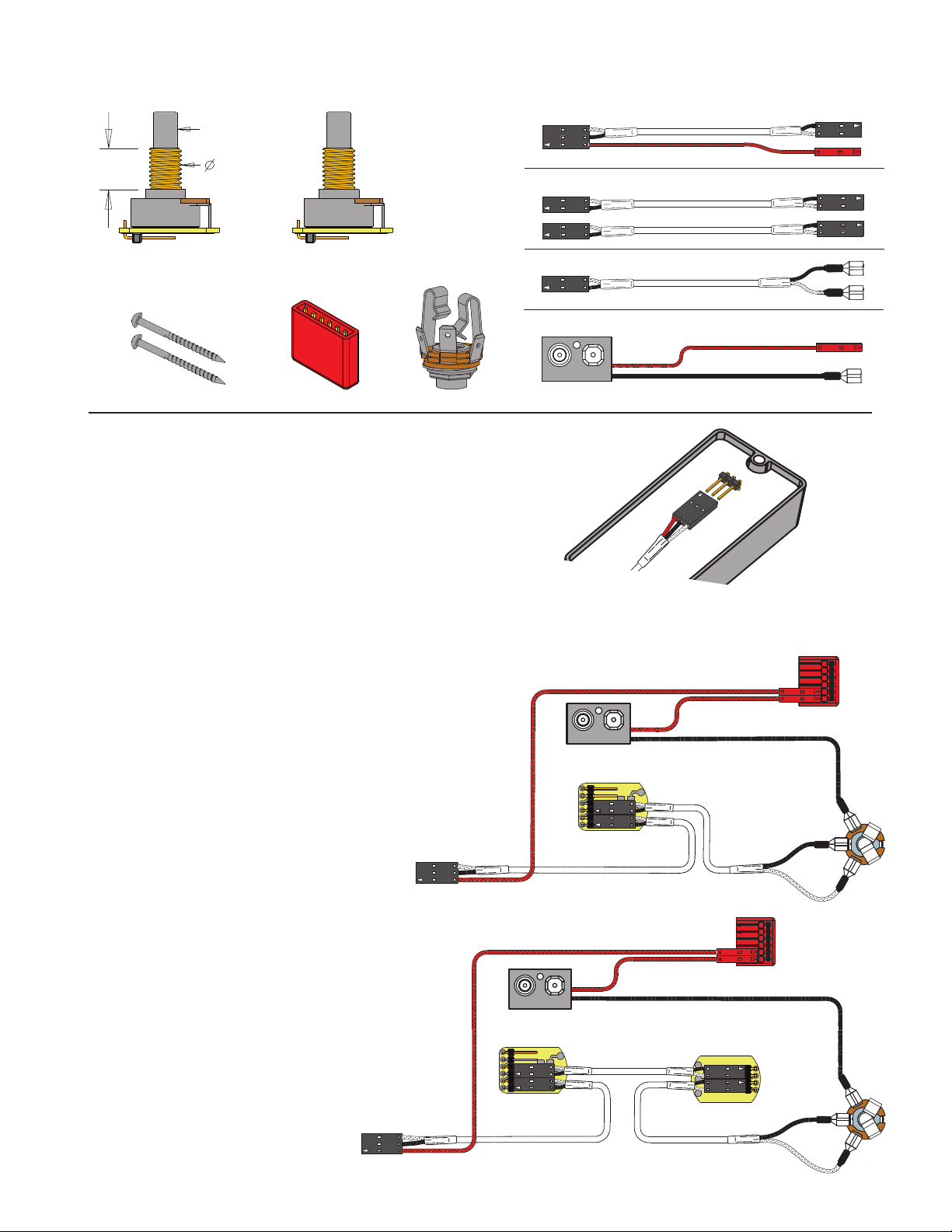
****Tips and Tricks**** Start your installation by:
****Tips and Tricks**** Start your installation by:
1) Determine which type output jack your instrument has.
1) Determine which type output jack your instrument has.
A Stereo 12B type is Included, but if you have a long panel jack
A Stereo 12B type is Included, but if you have a long panel jack
a SwitchCraft 152B Long Panel Jack will be required.
a SwitchCraft 152B Long Panel Jack will be required.
2) Remove the strings, remove any existing Pickups and controls
2) Remove the strings, remove any existing Pickups and controls
(remember the order and function of each control)
(remember the order and function of each control)
3) Determine a good spot for the Pickup Buss and make sure the
3) Determine a good spot for the Pickup Buss and make sure the
cable or wires from the selection switch will reach the Pickup Buss,
cable or wires from the selection switch will reach the Pickup Buss,
4) Install the EMG Volume and Tone Controls and tighten them in.
4) Install the EMG Volume and Tone Controls and tighten them in.
5) Then install the pickups keeping any excess cable under the pickup
5) Then install the pickups keeping any excess cable under the pickup
rather than in the control cavity.
rather than in the control cavity.
6) IMPORTANT: EMG Active pickups do not require a string ground wire!
6) IMPORTANT: EMG Active pickups do not require a string ground wire!
DO NOT Reconnect the string ground, it is unnecessary.
DO NOT Reconnect the string ground, it is unnecessary.
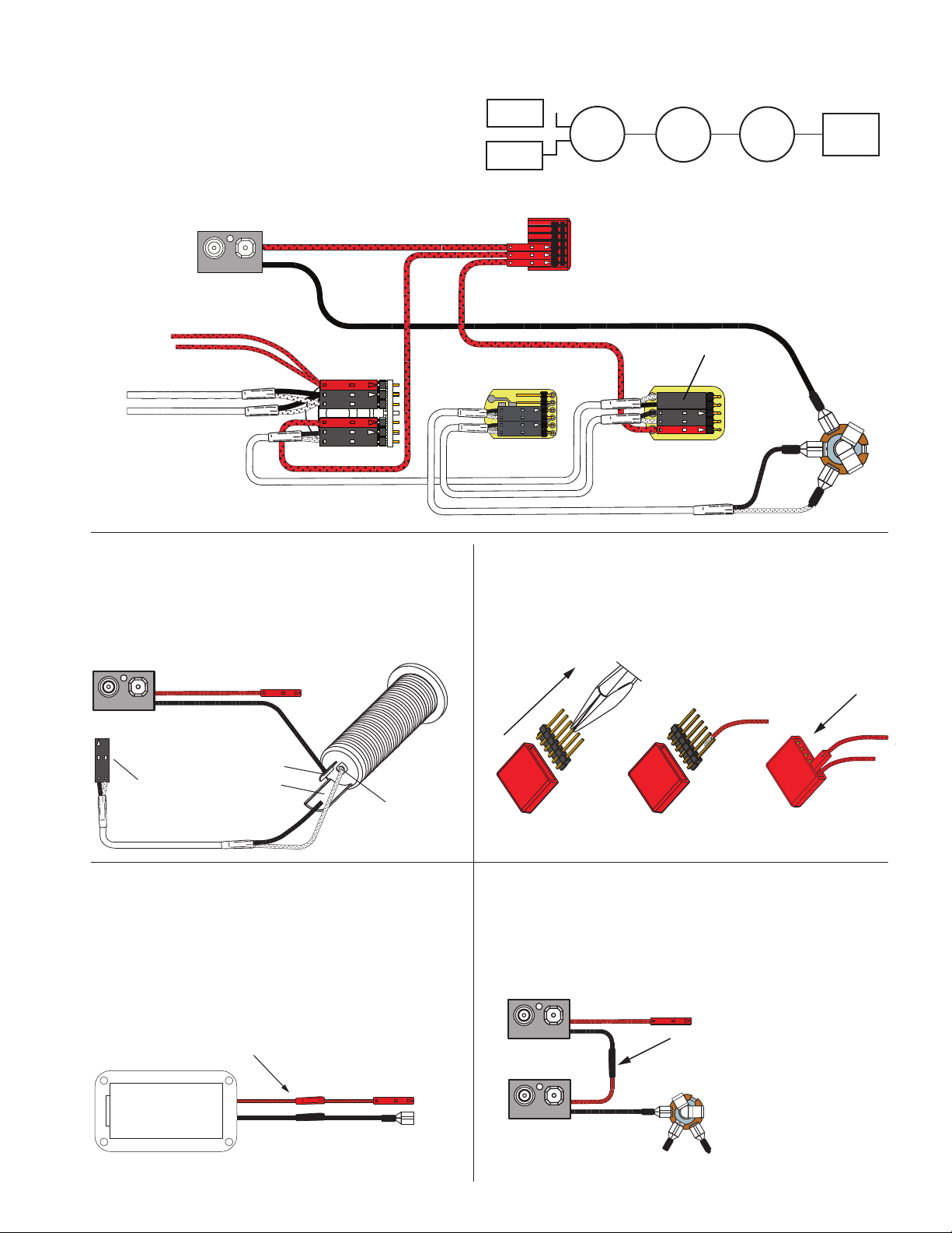
OUTPUT TO...
If your instrument has a selection switch:
Shown at the right is the EMG B245 Pickup Buss which is used for
instruments that have 2 pickups and a 3 position selection switch.
If you have a selection switch and want your installation to
remain solderless, you’ll need a B245 Buss.
or call: 800 821-1446 to get the buss.
BATTERY
NEG (-)
RED
RED
BATTERY
BUSS