JMASTER SET INSTRUCTIONS Page 2
General Notes:
Every attempt has been made to make this a solderless installation.
There are some instances where this is not possible;
1) If your instrument uses a long panel output jack and you had passive pickups,
you will need a new stereo output jack. The Switchcraft 152B is recommended.
Soldering to the new jack will be required, refer to Diagram #6.
2) If your instrument has a battery holder installed, soldering may be required
to splice its wires to the EMG battery cable. Refer to Diagram #8.
3) Instruments with two pickups may need soldering to the selection
switch for some installations.
Installation (Two Pickup Guitars with Selection Switch):
Guitars with two pickups and a selection switch will use the EMG B245 Pickup Buss
as shown in Diagram #2. Find a place to mount the Buss in the control cavity before
starting. Then, after the cables are routed use the velcro to mount it securely.
Before restringing your guitar, it’s helpful to check the function of your pickups
and controls by performing a “tap test” while plugged into your amplifier set to a
low volume. Tap gently on the pickups with a small screwdriver to confirm your
pickups are working and that your wiring harness has been properly connected.
Direct mounting your pickups will require placing hard foam beneath each pickup.
Many instruments will already have foam underneath the stock pickups, but you
may also cut a piece from the packaging foam that comes with your EMG Pickups.
****Tips and Tricks**** Start your installation by:
****Tips and Tricks**** Start your installation by:
1) Determine which type output jack your instrument has.
1) Determine which type output jack your instrument has.
A Stereo 12B type is Included, but if you have a long panel jack
A Stereo 12B type is Included, but if you have a long panel jack
a SwitchCraft 152B Long Panel Jack will be required.
a SwitchCraft 152B Long Panel Jack will be required.
2) Remove the strings, remove any existing Pickups and controls
2) Remove the strings, remove any existing Pickups and controls
(remember the order and function of each control)
(remember the order and function of each control)
3) Determine a good spot for the Pickup Buss and make sure the
3) Determine a good spot for the Pickup Buss and make sure the
cable or wires from the selection switch will reach the Buss
cable or wires from the selection switch will reach the Buss
4) Install the EMG Volume and Tone Controls and tighten them in
4) Install the EMG Volume and Tone Controls and tighten them in
5) Then install the pickups keeping any excess cable under the pickup
5) Then install the pickups keeping any excess cable under the pickup
rather than in the control cavity.
rather than in the control cavity.
6) IMPORTANT: EMG Active pickups do not require a string ground wire!
6) IMPORTANT: EMG Active pickups do not require a string ground wire!
DO NOT reconnect the string ground, it is unnecessary and may pose
DO NOT reconnect the string ground, it is unnecessary and may pose
a shock hazard if using a vintage amplifier.
a shock hazard if using a vintage amplifier.
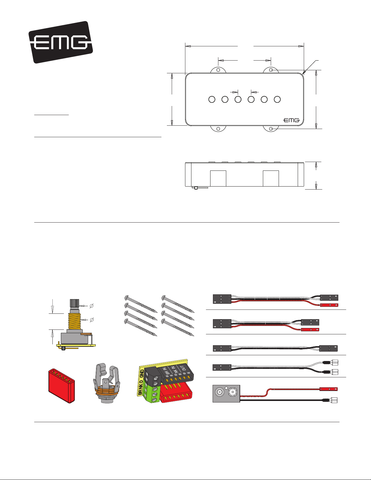
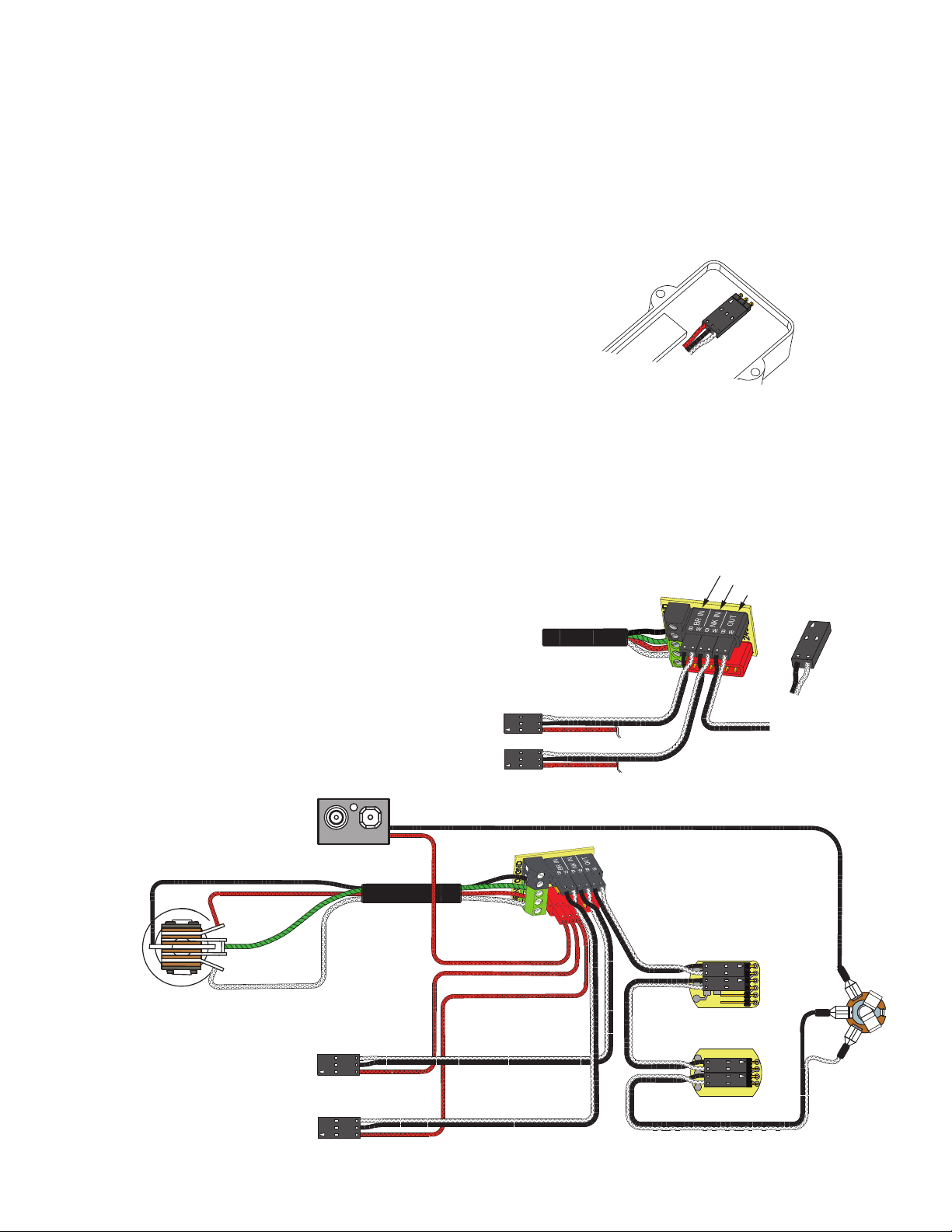
Diagram #1
Insert the plug onto the 3 pin header
of the pickup as shown above.
Note the orientation arrow.
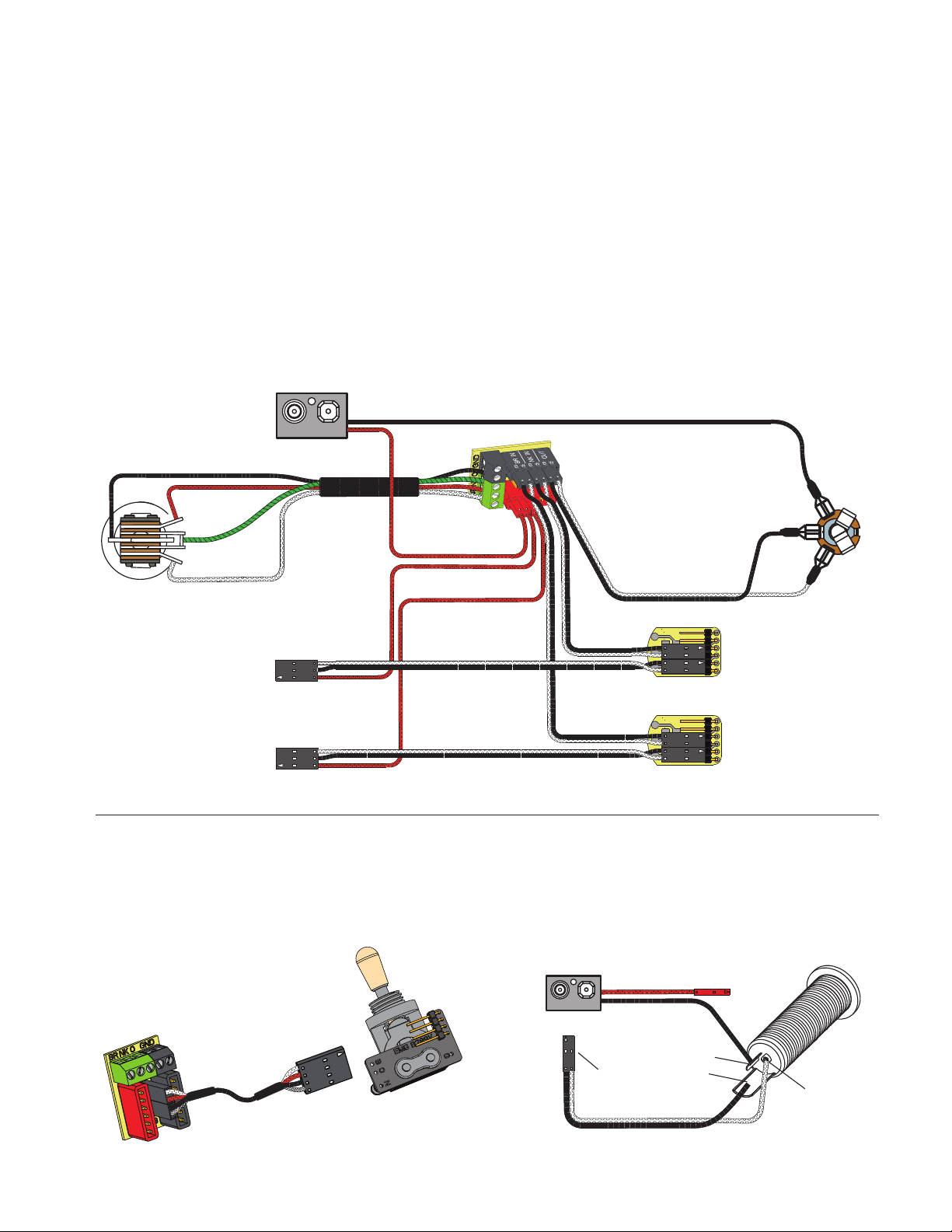
Refer to Diagrams #1, #2, and #3
1) Install the pickups and and route the pickup cables to the control cavity.
If the cables are too long, wind up the excess and tuck it inside the cavity
2) Mount the Volume and Tone controls onto the body or pickguard.
Plug both pickup cables into the B245 Pickup Buss (BLACK Shroud) as shown.
Refer to diagram #2, Bridge Pickup to position 1 and Neck Pickup to position 2
3) Plug a connect cable from the Pickup Buss (position 3) to the Master Volume
control as shown in Diagram #3
4) Plug a connect cable from the Master Volume to the Master Tone as shown.
5) Strip the insulation from the switch wires and Insert them into the GREEN
Terminal Block and tighten the screws with a small screwdriver.
The Bridge pickup goes to the BR Terminal
The Neck pickup goes to the NK Terminal
The Output of the switch goes to the O Terminal
If there is a ground wire coming from the switch, insert it into one of the black
GND terminals on the block.
If using a solderless EMG 3-way toggle, refer to Diagram #5.
6) Plug the output cable onto the Master Tone control and connect the output
wires to the output jack by pushing the connectors on as shown.
WHITE wire onto the TIP (T) contact,
BLACK wire onto the SLEEVE (S) contact
BLACK Battery Negative wire onto the RING (R) contact.
7) Plug the RED wires of the pickups onto the V+ Buss (RED Shroud)
along with the RED wire of the battery clip.
Extra pins on the V+ Buss are for EMG Accessories.
8) Wrap the battery in a piece of insulating foam and place it securely in the
control cavity.
9) Before restringing your instrument, perform a “tap test” as described above
to check that your setup performs as expected.
2 Pickups / Toggle Select Switch / Master Volume and Tone
Diagram #3
2 Pickups
Toggle Style Select Switch
Master Volume & Master Tone
Diagram #2
BRIDGE PICKUP INPUT
NECK PICKUP INPUT
OUTPUT
NECK PICKUP
BRIDGE PICKUP
TO SELECTION SWITCH
PLUG IN
LIKE THIS!
OUTPUT TO
MASTER VOLUME
TONE
B124rH
VOLUME
B122rH
MASTER
TONE
BRIDGE PICKUP
NECK PICKUP
BATTERY
NEG (-)
MASTER
VOLUME
T
R
S
OUTPUT CABLE
RED
RED
RED
GROUND
BRIDGE P/U
NECK P/U
OUTPUT
- 9V +