EMG MM-CS Service manual

INSTALLATION INFORMATION
EMG MODEL: MM5CS
Warranty
All EMG Pickups and accessories are warranted for a period of two years. This warranty does not cover failure due to improper installation, abuse or damage. If
upon examination the pickup is determined to be defective, a replacement will be made. Warranty replacement products are covered by this same warranty. This
warranty covers only those pickups and accessories sold by authorized EMG Dealers. This warranty is not transferable.
© 2010 Copyright EMG INC. All Rights Reserved.
PO BOX 4394
SANTA ROSA, CA
95402 USA
P (707) 525-9941
F (707) 575-7046
EMGPICKUPS.COM
0230-0188A
*Note: C/S (Ceramic and Steel)
SPECIFICATIONS: MODEL:
MM-CS
Logo Color Silver
Magnet Type * C/S
Resonant Frequency (KHz) 2.50
Output Voltage (Finger, Thumb) 2.00
Output Voltage (Thump) 4.50
Output Noise (60 Hz) -107
Output Impedance (Kohm) 10
Current @9V (Microamps) 80
Battery Life (Hours) 3000
Maximum Supply (Volts DC) 27
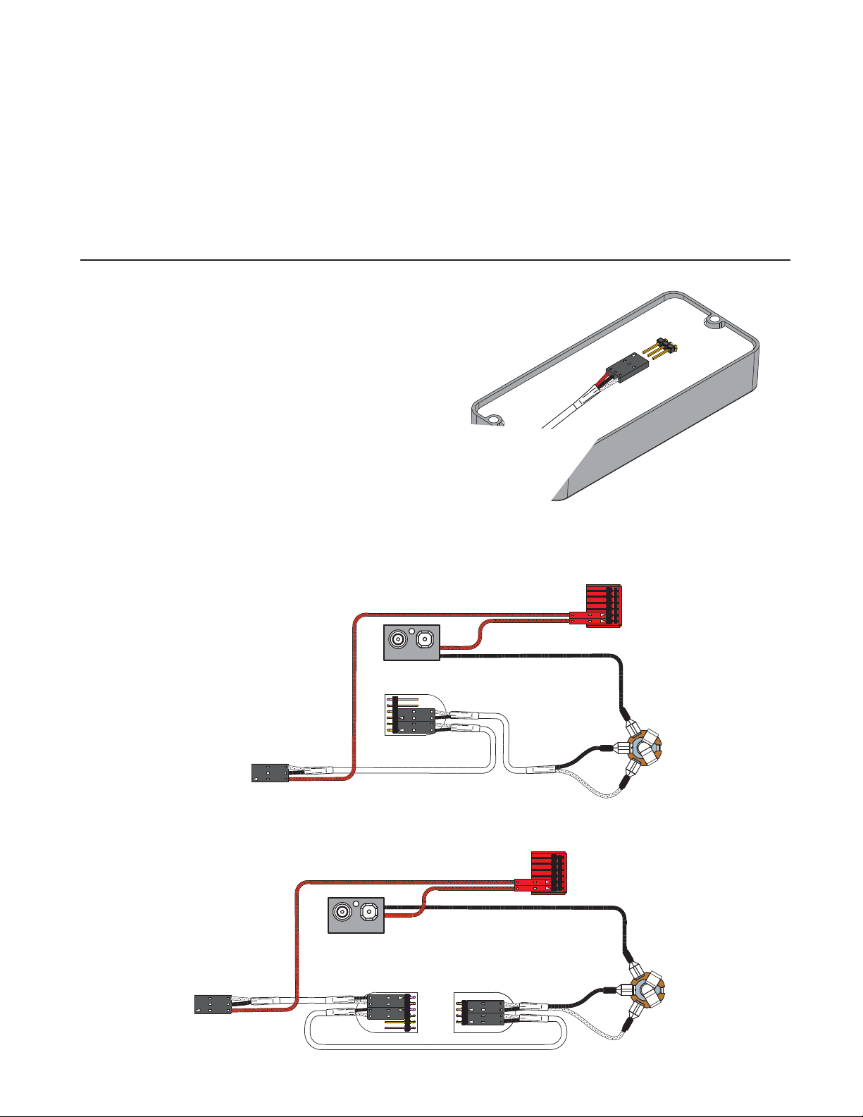
IMPORTANT INSTALLATION NOTES:
1) Only one 9-Volt battery is required to power the pickups (unless
otherwise recommended) and any accessories such as the EXB,
BTC, B125 Blend, and BQ Controls.
Use an Alkaline or Lithium battery for longest life.
2) The Volume and Tone controls included with this EMG System are
25K Ohm. This value is required for the system to work correctly.
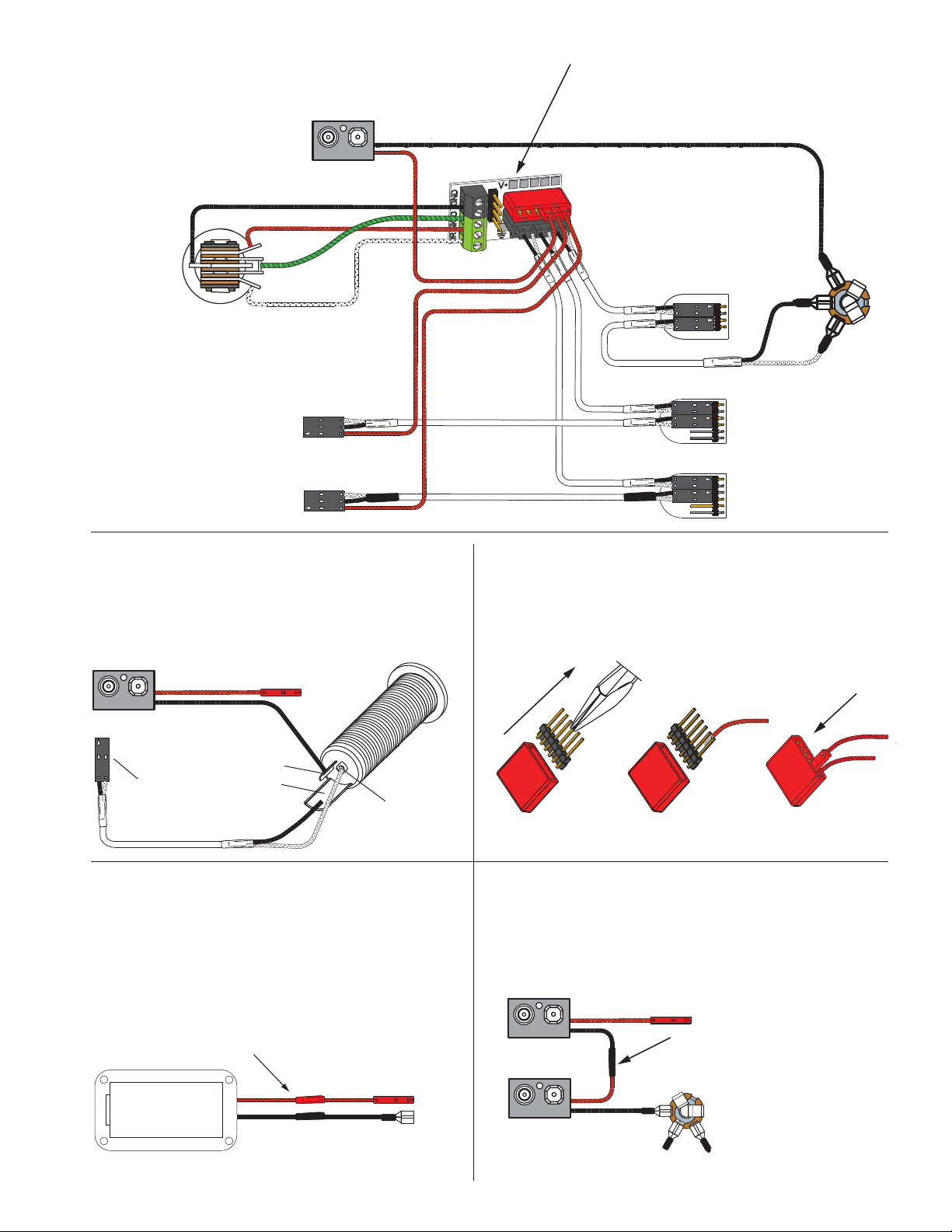
3) A stereo output jack (12B) is included with the EMG Pickups;
it grounds the black battery wire to turn on the pickups when
the plug is inserted into the jack. If you are replacing passive
pickups, make sure to use the jack included. If your guitar has a
long panel jack (see Page 4) make sure it is a stereo type, a
Switchcraft 152B is recommended.
4) When installing EMG Active Pickups, DO NOT connect the bridge
ground wire. This wire is usually soldered to a volume or tone
control casing and goes to the bridge. This wire grounds the
strings and uses them and your body as a shield against hum and
buzz. It also creates a shock hazard.
EMG Pickups are shielded internally and DO NOT require string
grounding. This greatly reduces the possibility of reverse
polarity shock from microphones and other equipment.
5) EMG Active Pickups have very little magnetism compared to
passive pickups. We recommend you adjust the pickups as
close to the strings as possible. Sustain and string movement
will not be inhibited by close adjustment.
6) If your installation is different from the diagrams in these
instructions or you need additional diagrams visit our website:
emgpickups.com for a complete listing of available diagrams.
7) SPECIAL NOTE:
The diagrams shown are for EMG Active Pickups.
All diagrams show the Red Wire coming from the pickups
connected to the battery. If you are installing EMG-HZ
Passive Pickups refer to their diagrams. The Red Wire of
the HZ Pickup is NOT for battery power, it is a coil wire.
.750
R .250 TYP
4.400
1.935
4.180
.945
.850
.125 DIA. MOUNTING HOLES
ABOUT THE MM5CS:
The MM5CS Pickup is a direct replacement for the Music Man 5-String Pickup. It has an aperture of .950 Inches that yields a very high output.
The Ceramic and Steel Design was chosen for milder string attack and overall mellower tone. The MM5CS will operate on 9-Volts, but It is
recommended to run the MMCS with a +18 Volt Supply (2 - 9-Volt Batteries) in order to handle the signal strength, especially if you play
the instrument hard (See Page 4 for 18-Volt wiring).
EMG accessories like the EXB, BTC or VMC Controls can be added to further enhance your experience.
MAXIMUM RECOMMENDED STRING WIDTH 3.08"
3.460

Diagram #2
One Pickup
One Volume
General Notes:
Every attempt has been made to make this a solderless installation.
There are some instances where this is not possible;
1) If your instrument uses the long panel output jack and you had passive pickups
you will need a new stereo output jack, the Switchcraft 152B is recommended.
Soldering to the new jack will be required, see page 4.
2) Power Supply tips are on page 4. If your instrument has a battery holder,
you are installing this pickup with an older EMG, or you want to supply your
instrument with +18 Volts, see page 4 for tips to avoid soldering.
If you are installing only one pickup use the instructions on this page.
If you are installing two pickups go to page 3 and begin there.
Installation Instructions:
EMG Model: MM5CS
MM5CS Page 2
Diagram #1
Insert the plug onto the 3 pin header
of the pickup as shown above.
Note the orientation arrow.
MASTER
VOLUME
FROM PICKUP
OUTPUT
T
R
S
BATTERY
NEG (-)
RED
RED
BATTERY
BUSS
****Tips and Tricks****
Start your installation by:
1) Read the General Notes on Page 2 if you haven’t already
and determine if you have the right output jack for your
instrument. A Stereo 12B type (Included) or a 152B Long Panel
Jack will be required.
2) Remove the strings
3) Remove any existing Pickups and controls
(remember the order and function of each control)
4) Install the EMG Volume and Tone Controls and tighten them in.
5) Then install the pickups keeping any excess cable under the pickup
rather than in the control cavity.
OUTPUT CABLE
- 9V +
Diagram #3
One Pickup
One Volume
One Tone
OUTPUT
T
R
S
PASSIVE
TONE
FROM PICKUP
BATTERY
NEG (-)
RED
RED
BATTERY
BUSS
OUTPUT CABLE
MASTER
VOLUME
- 9V +
Installation (One Pickup Guitars):
1) Plug the pickup cable onto the EMG Pickup header as shown
in Diagram #1 and route the cable to the control cavity.
If the cable is too long, wind up the excess and keep it
under the pickup if possible.
Master Volume control only
2) Refer to Diagram #2. Plug both the Pickup cable and the output
cable onto the Volume control as shown, then go to step 4.
Master Volume and Tone control
3) Refer to Diagram #3. Plug the Pickup cable onto the Volume
control as shown. Plug a coax cable from the Volume control
to the Tone control. Plug the output cable onto the tone
control as shown.
4) Connect the wires of the output cable to the output jack by
pushing the connectors on as shown.
WHITE wire to the TIP (T) contact,
BLACK wire to the SLEEVE (S) contact
BLACK Battery Negative wire to the RING (R) contact.
5) Using the battery buss, insert the RED wire of the pickup,
and the battery RED wire. Extra pins can be used for
EMG Accessories.
6) Put the battery in the insulating foam piece provided
and place it securely in the control cavity.
We suggest that you plug in the instrument and
test it before closing the control cavity.

MM5CS Page 3
Installation Instructions:
EMG Model: MM5CS
2 Pickups, 2 Volume controls and Master Tone, no selection switch
J-Bass Style wiring
Refer to Diagram #4
1) Install the Pickups and route the Pickup cables to the control cavity.
If the cables are too long, keep any excess under the pickup.
2) Mount the Volume and Tone controls into the body / pickguard.
Plug the Neck Pickup Cable onto the Neck Volume control.
Plug the Bridge Pickup Cable onto the Bridge Volume control.
3) Plug a coax cable from the Neck Volume control to the Bridge Volume
Control.
4) Plug a coax cable from the Bridge Volume control the Master Tone control.
5) Plug the output cable onto the Master Tone control and connect the output
wires to the output jack by pushing the connectors on as shown.
WHITE wire onto the TIP (T) contact,
BLACK wire onto the SLEEVE (S) contact
BLACK Battery Negative wire onto the RING (R) contact.
6) Plug the RED Wires of the pickups onto the V+ Supply Buss (RED Shroud)
along with the RED of the battery clip.
Extra pins on the V+ Supply Buss are for EMG Accessories.
7) Put the battery in the insulating foam piece provided and place it securely in the
control cavity.
We suggest that you plug in the instrument and test it before closing the
control cavity.
- 9V +
MASTER
TONE
NECK
VOLUME
OUTPUT
T
R
S
OUTPUT CABLE
BRIDGE
VOLUME
MASTER
VOLUME
BATTERY
NEG (-) BLACK
ACTIVE
TONE
NOTE REVERSED CONNECTOR!
Diagram #5 (preferred wiring order)
B125 Active Balance Control
Active Tone / Master Volume
RED
RED
RED
NECK
PICKUP
BRIDGE
PICKUP
ABC
CONTROL
ACTIVE
TONE
MASTER
VOLUME
OUTPUT
JACK
BOTTOM VIEW
B125
ACTIVE BALANCE
CONTROL
- 9V +
OUTPUT
T
R
S
BATTERY
BUSS
BATTERY
BUSS
This installation can be used for instruments with 3 control positions like
the diagram above, but use a Balance control instead of 2 Volume controls.
The Active Tone Control shown in this diagram can be replaced with the
EMG-EXB Expander, or the EMG-BTC Control (Active Bass and Treble EQ).
BRIDGE PICKUP
NECK PICKUP
Diagram #4
Volume / Volume
Master Tone (Passive)
EMG Neck Pickup
(Upper 3 pin header)
EMG Bridge Pickup
(Lower 3 pin header)

TIP
RING
SLEEVE
Diagram #7
FROM TONE
OR VOLUME
MM5CS Page 4
Diagram #9
If the instrument has a Battery Holder:
If your instrument has a 9 or 18-Volt battery holder you can still
use the EMG Connectors to supply power to the pickups.
Simply cut and strip the wires from the battery clip provided.
Twist the wires together (Red to Red and Black to Black) and
use the shrink tubing included to cover the connections.
Soldering the wires is recommended.
9/18 VOLT
BATTERY
HOLDER
Cover these connections with the
shrink tubing provided.
BLACK to RING terminal
of the Output Jack
RED to BATTERY OR PICKUP BUSS
BLACK to RING terminal
of the Output Jack
RED TO BATTERY BUSS (+18Volts)
Diagram #10
BATTERY
NEG (-)
RED to BATTERY BUSS
Soldering to the 152B Panel Jack:
If your instrument has a long Panel Jack like the one below
you will have to solder the output cable as shown.
Ground (Black) to the sleeve
Signal (White) to the Tip
Battery Negative (Black) to the Ring
OUTPUT
T
R
S
NK VOLUME
FROM NECK PICKUP
FROM BRIDGE PICKUP
BR VOLUME
BATTERY
NEG (-)
MASTER
TONE
Diagram #6
2 Pickups
Toggle Style Switch
Volume each Pickup (Volumes are independent)
Master Tone
OUTPUT CABLE
RED
RED
RED
GROUND
BRIDGE P/U
NECK P/U
OUTPUT
- 9V +
- 9V +
- 9V +
- 9V +
T
R
S
RED
BLACK
Using the B157 Pickup Buss:
If your instrument has 2 Pickups and a selection switch
you will be using the B157 Pickup Buss to send the pickup
signals to the selection switch. Refer to the
B157 Instructions included.
Diagram #8
13
Soldering to the battery buss:
If your instrument has an older EMG Pickup you can solder the
pickup RED wire to the buss. Simply use some needle nose pliers,
pull out the V+ header and solder the RED Wire from the pickup(s)
to any of the pins and then re-insert the header into the housing.
2
+18 Volt Wiring Option:
If you want to operate your instrument at +18 Volts for more
headroom then use 2 batteries wired as below.
Also, if you are using any type of EQ in your instrument
(EMG-BT, BQ) or anything that boosts the pickup signal then
+18 Volts is recommended.
Solder the Black and Red
wires together and cover
the connection with shrink
tubing, or other insulation.
This manual suits for next models
1
Other EMG Accessories For Musical Instruments manuals

EMG
EMG 89-X Service manual

EMG
EMG AB 220 Service manual

EMG
EMG Pro KH-21 Series Service manual

EMG
EMG P Service manual

EMG
EMG EMG-B344 Series Service manual

EMG
EMG Pso VG-20 Series Service manual

EMG
EMG BQC-HZ SYSTEM Service manual

EMG
EMG 57-TW Service manual

EMG
EMG MMTW Service manual

EMG
EMG PJ5 Service manual
Popular Accessories For Musical Instruments manuals by other brands

Auralex Acoustics
Auralex Acoustics Deep6 Installation & user guide

DiMarzio
DiMarzio J All-in-One Quick Start Guide

Fishman
Fishman FLUENCE CUSTOM MATT HEAFY Series installation guide

K&K Sound
K&K Sound VIOLINISSIMO product manual

Konig & Meyer
Konig & Meyer Spider Pro 18876 manual

GuitarPCB
GuitarPCB FXCT manual