ABC (B125)
BALANCE
CONTROL
BASS
CONTROL
TREBLE
CONTROL
NECK
PICKUP
BRIDGE
PICKUP
ABC
CONTROL
BQS
CONTROL
MASTER
VOLUME
OUTPUT
JACK
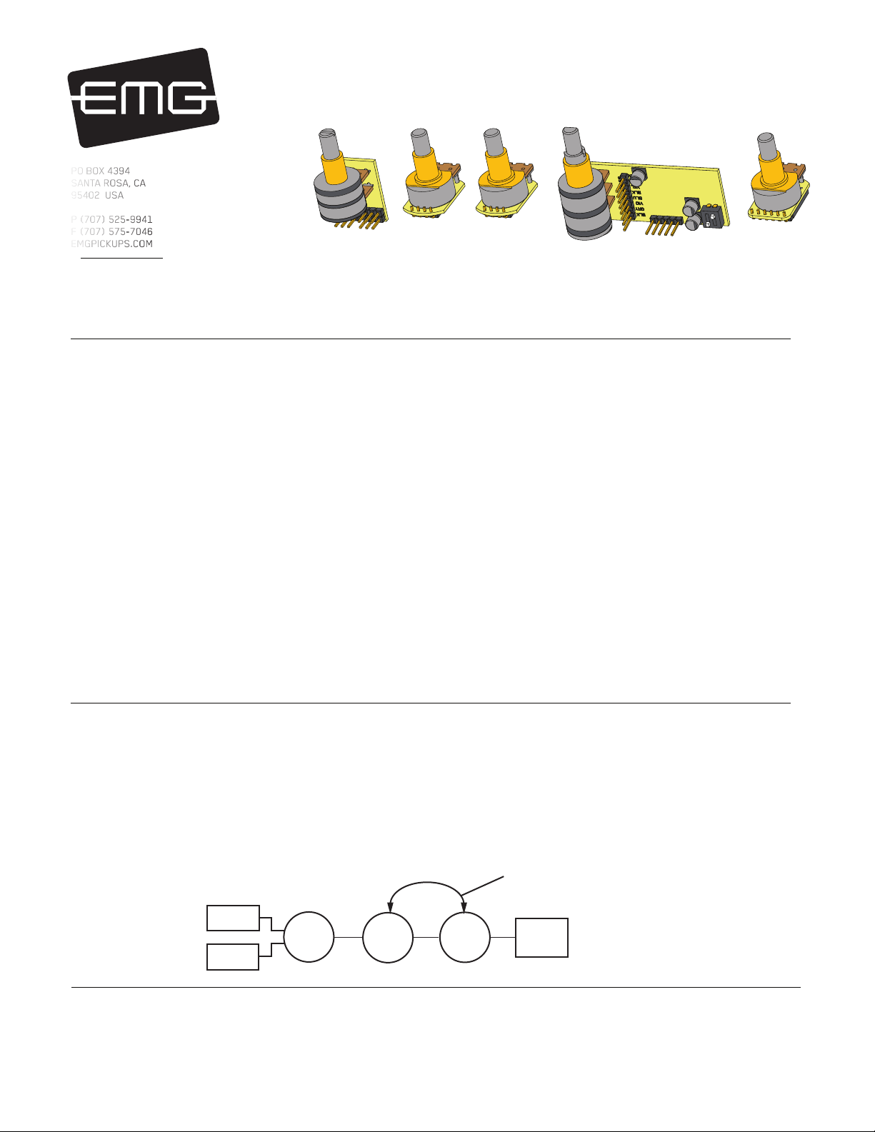
MASTER VOLUME AND
BQS CONTROL ORDER
CAN BE REVERSED
MASTER
VOLUME
MID-RANGE
CONTROL
0230-0214rL
INSTALLATION INFORMATION
EMG MODEL: BQS-HZ SYSTEM
(PASSIVE PICKUP INPUT)
Installation notes:
Battery Power:
If you play the instrument very hard, and are boosting the bass, mid, or treble with the BQS, you should consider operating the guitar on +18
Volts (2 Batteries in series, see page 4). If you play mildly and use a minimum of boost the instrument should operate easily on a single 9-Volt
battery. Use an Alkaline or Lithium battery for the best battery life and always unplug your guitar when you’re not using it.
Warranty
All EMG Pickups and accessories are warranted for a period of two years. This warranty does not cover failure due to improper installation, abuse or damage. If
upon examination the pickup is determined to be defective, a replacement will be made. Warranty replacement products are covered by this same warranty. This
warranty covers only those pickups and accessories sold by authorized EMG Dealers. This warranty is not transferable.
© 2021 Copyright EMG INC. All Rights Reserved.
PO BOX 4394
SANTA ROSA, CA
95402 USA
P (707) 525-9941
F (707) 575-7046
EMGPICKUPS.COM
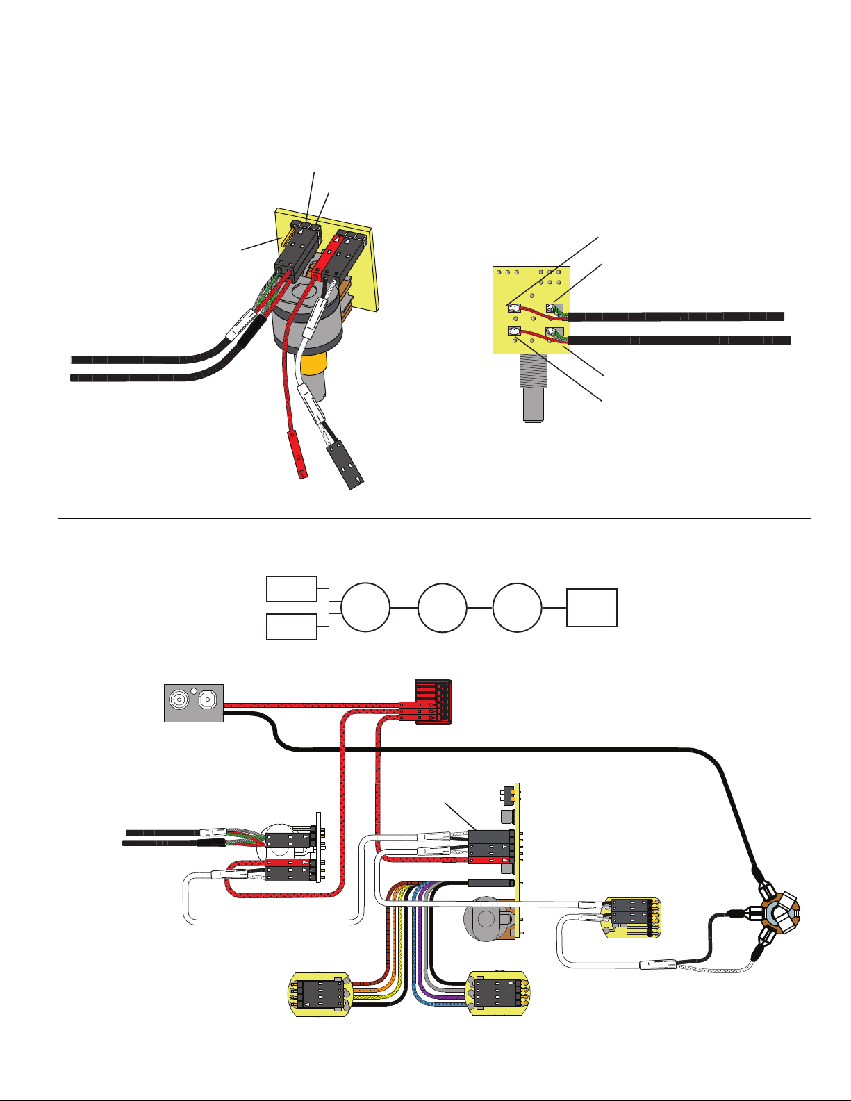
wiring order:
Below is a diagram of the typical wiring order of the controls. Often the Volume control is closer to the pickups than the BQS Control making it
difficult to wire the instrument. It is preferable to have the Master Volume control last in the signal chain before the output jack. If this isn’t
possible it’s no worry, either wiring order is acceptable.
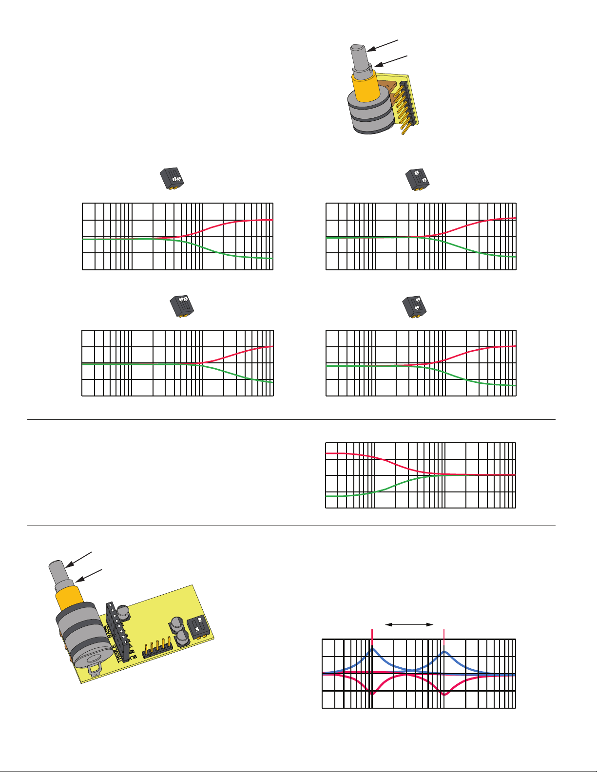
ABOUT THE BQS-HZ SYSTEM:
The BQS-HZ System is a complete control system for bass guitars. Active Balance, Master Volume and EQ circuits are included. The EQ effects
are illustrated in the graphs on the next page. They allow you separate control over bass, midrange, and treble. Rotate the controls clockwise
to boost, counterclockwise to cut. There is a center detent for flat response.
The mid-range control has a variable frequency knob that allows you to sweep through the mid-frequency range from 100Hz to 1KHz. This
selects the frequency to boost or cut.
Included in the system are:
1) Active Balance Control (B125)
The B125 Active Balance Control is designed for Passive Pickups. It allows loss-free balance between two pickups and has a center detent for
the middle position. If you are using EMG Active pickups you can also use the B125 although the B118 Active Balance Control which features
inputs for Active Pickups has lower noise.
2) BQS Control 3-band equalizer for Bass guitar. The BQS features dual-pole filters for broadband equalization. The primary feature of the BQS
System is the variable mid-range frequency selection from 100 to 1KHz along with boost or cut of the chosen frequency. An additional feature
of the BQS Control is a 2-position dip-switch that controls the slope of the high frequency response. By choosing one of the four combinations
the high frequency response can be tailored to your liking.
3) Master Volume control, output jack, battery buss and clip.
Specifications for each of the EMG products included in the BQS-HZ System are available online.
Go to: http://www.emgpickups.com
PASSIVE
PICKUP
INPUTS