Emhart Teknologies POP ProSet 1600 Series User manual

ProSet™1600 Series
Rivet
Tool
Service Manual

Page 2 Emhart Teknologies - 50 Shelton Technology Center, Shelton CT 06484 - Tel. (203) 924-9341 - Fax (800) 225-5614

Contents
Introduction.............................................................................................................................................................. 3
Safety Instructions................................................................................................................................................... 4
Specifications........................................................................................................................................................... 5
Packaged Accessories ............................................................................................................................... 5
Tool Requirements...................................................................................................................................... 5
ProSet™ 1600 Tool Dimensions................................................................................................................. 6
Common Nosepieces................................................................................................................................. 7
Chapter 1 – Upper and Lower Handle..................................................................................................................... 8
Chapter 2 – Hydraulic Piston..................................................................................................................................11
Chapter 3 – Trigger Valve...................................................................................................................................... 13
Chapter 4 – Pulling Head Adaptor......................................................................................................................... 14
Chapter 5 – Ejector & MCS Valve ......................................................................................................................... 16
Chapter 6 – Return Spring..................................................................................................................................... 18
Chapter 7 – Jaws / Jaw Case................................................................................................................................ 20
Chapter 8 – Intensifier Chamber ........................................................................................................................... 22
Chapter 9 – Oil Filling Procedure .......................................................................................................................... 23
Chapter 10 – Shut off Air Fitting ............................................................................................................................ 27
Chapter 11 – Grip Cover........................................................................................................................................ 28
Chapter 12a – Back End (ProSet1600)................................................................................................................. 30
Chapter 12b – Back End (ProSet1600MCS)......................................................................................................... 31
ProSet™ 1600/1600MCS Diagram ....................................................................................................................... 32
Parts List................................................................................................................................................................ 34
Safety Data............................................................................................................................................................ 36
Troubleshooting..................................................................................................................................................... 37
EC Declaration of Conformity................................................................................................................................ 38
Introduction
POP®ProSet™ 1600 tools are light weight Air/Hydraulic rivet setting tools recommended for use with genuine
POP®Brand Rivets per following chart:
Rivet Diameter
Rivet Type Material
(Body – Mandrel) 3/32” (*)
[2.4 mm] 1/8”
[3.0 - 3.2 mm] 5/32”
[4.0 mm]
Al – Al 999
Al – St / SS 999
St – St 999(†)
Open End & MultiGrip
SS – SS; Mo – St /SS 99
Al – Al 999
Al – St / SS; Cu – St 999()
St – St 99
Closed End
SS – SS 99
LSR Rivets Al – Al 999
HR™ Rivets St – St 99
T - Rivet Al – St 999
Self Plugger St – St 99
Al: Aluminum, St: Steel, SS: Stainless Steel, Cu: Cooper, Mo: Monel
(*) Use FAN239-176 Jaw pusher set up.
(†) Exclude MultiGrip
() Set air pressure at 90 psi (6.2 bar).
Emhart Teknologies - 50 Shelton Technology Center, Shelton CT 06484 - Tel. (203) 924-9341 - Fax (800) 225-5614 Page 3

Safety Instructions
TO INSURE PROPER FUNCTIONING AND SAFE OPERATION READ THIS MANUAL CAREFULLY
BEFORE SETTING UP OR OPERATING THE POP®ProSet™ 1600 SERIES TOOLS
1. DO NOT use this tool in a manner other than that recommended by Emhart Teknologies.
2. Always wear eye protection when using or when near a tool that is in use.
3. This tool is NOT designed for use in explosive atmospheres.
4. Inspect tool for damage before connecting to air supply including all air connections.
5. Trained personnel must perform tool repair and/or maintenance at the prescribed intervals.
6. Disconnect the air supply when adjusting, servicing or removing any part of the tool.
7. Keep fingers off the trigger when connecting the air supply or if the air supply fails.
8. Keep fingers away from the front of the tool when connecting the air supply or setting rivets.
9. DO NOT point the tool at anyone.
10. DO NOT operate tool with the nose housing removed.
11. DO NOT operate tool without the Deflector or Collector.
12. DO NOT modify the tool in any way. Modification will make void any applicable warranties
and could result in damage to the tool or physical injury to the user.
13. DO NOT look into the tool from the front or the back during use or when connected to air
supply.
14. The operating pressure must not exceed 100 psi (6.9 bar).
15. DO NOT direct tool exhaust towards anyone.
16. Wash hands if exposed to hydraulic fluid or lubricant.
17. Keep hair, fingers and loose clothing away from moving parts of the tool.
Page 4 Emhart Teknologies - 50 Shelton Technology Center, Shelton CT 06484 - Tel. (203) 924-9341 - Fax (800) 225-5614

Specifications
ProSet™ 1600 ProSet™ 1600MCS
Weight 2.14 lbs. (0.97 kg) 2.29 lbs. (1.04 kg)
Length 10.83” (275 mm) 10.71” (272 mm)
Height 8.94” (227 mm) 8.94” (227 mm)
Tool stroke 0.71” (18 mm) 0.71” (18 mm)
Pulling force 1090 lbs @ 90 PSI (4850 N @ 6.2 bar) 1090 lbs @ 90 PSI (4850 N @ 6.2 bar)
Air consumption
0.043 cu. ft. per rivet
(1.22 liters per rivet) 2.47 scfm (MAX)
(70 ℓ/min (MAX))
Packaged Accessories
Qty Item PROSET 1600 PROSET 1600MCS Part No.
1 ProSet™ 1600 Rivet Tool 99-
1 Operating Instructions 99P449
1 Maintenance Manual 99P513
1 Nosepiece for 3 size open end rivets 99PRN314
1 Nosepiece for 4 size open end rivets Installed Installed
PRN414
1 Nosepiece for 5 size open end rivets 99PRN514
1 Jaw Pusher (Assy.) for 3/32” rivets 99FAN239-176
1 Air Line Assembly 99FAN239-157
1 4 mm Hex. Socket Screw Key 99DPN239-139
1 Warranty Card 99FG2185
Tool Requirements
Air supply * 6 scfm (150 l/min) Minimum
Recommended Operating Pressure 72.5-90 PSI (5.0-6.2 Bar) dry, filtered
Maximum Operating Pressure 100 PSI (6.9 Bar) dry, filtered
Hydraulic Oil ** POP®p/n: PRG540-130 [1 qt. (.945 ml)]
Jaw Lubricant ** POP®p/n: PRG510-130 [6 oz. (177 ml)]
Seal Lubricant ** POP® p/n: PSA075508P [1 ¾ oz. (54 g)]
(*) Note: For best results and long service life, use dry, filtered air supply.
(**) Note: See lubricant safety information.
Emhart Teknologies - 50 Shelton Technology Center, Shelton CT 06484 - Tel. (203) 924-9341 - Fax (800) 225-5614 Page 5

ProSet™ 1600 Tool Dimensions
.682” (17.3 mm)
10.83” (275 mm)
8.94” (227 mm)
2.99” (76 mm)
3.27” (83 mm)
ProSet™ 1600
1.83” (46.5 mm)
3.23” (82 mm)
1.82” (46.3 mm)
10.71” (272 mm)
3.27” (83 mm)
2.99” (76 mm)
.682” (17.3 mm)
8.94” (227 mm)
ProSet™ 1600 MCS
3.23” (82 mm)
1.82” (46.3 mm)
1.83” (46.5 mm)
Page 6 Emhart Teknologies - 50 Shelton Technology Center, Shelton CT 06484 - Tel. (203) 924-9341 - Fax (800) 225-5614

Common Nosepieces
Included with the tool
se FAN239-176 instead of DPN239-144 (installed) when using 3/32” (2.4mm) or smaller diameter rivets.
*
Closed End HR Rivets
Rivet Diameter Open End Steel Mandrel Aluminum
Mandrel Aluminum
Body Steel
Body Jaw Pusher
2.0 mm PRN214 - - - -
FAN239-176*
(PRG402-02 - JAWS)
3/32” (2.4 mm) PRN314* - - - - FAN239-176*
1/8” (3.2 mm) or
7/64” (2.8 mm) PRN414* PRN424 PRN434 PRN414* PRN4K
5/32” (4.0 mm) PRN514* PRN524 PRN534 PRN514* - DPN239-144*
U
Emhart Teknologies - 50 Shelton Technology Center, Shelton CT 06484 - Tel. (203) 924-9341 - Fax (800) 225-5614 Page 7

Chapter 1 – Upper and Lower Handle
Apply grease around 8mm hole on Upper Handle
Assembly.
Grease: ShellALVANIA EP Grease1
Apply grease around 6mm hole.
Tighten the Sleeve Assembly to Upper Handle
Assembly
Hex Size: 19mm
Torque: 50±3 NM Sleeve Assy
Handle Upper
Assy
Set an Upper Plate(50) on the Lower Handle
Assembly.
Upper Plate
(50)
Handle Lower
Assy
Page 8 Emhart Teknologies - 50 Shelton Technology Center, Shelton CT 06484 - Tel. (203) 924-9341 - Fax (800) 225-5614

Insert the Lower Handle Assembly with the Upper
Plate (50) into the Sleeve Assembly.
Upper Plate
(50)
Handle Lower
Assy
Sleeve Assy
Position a Bottom Plate (62) as shown.
Bottom Plate
(62)
Start a Sleeve Lock Nut (61).
Tighten the Sleeve Lock Nut (61) with a 25mm
closed wrench.
Torque Values: 45±3Nm
Sleeve Lock Nut
(61)
Page 9 Emhart Teknologies - 50 Shelton Technology Center, Shelton CT 06484 - Tel. (203) 924-9341 - Fax (800) 225-5614

At this time, the Upper and Lower Handle are in the
same direction.
Page 10 Emhart Teknologies - 50 Shelton Technology Center, Shelton CT 06484 - Tel. (203) 924-9341 - Fax (800) 225-5614

Chapter 2 – Hydraulic Piston
Apply grease around the inner circumference of the
Upper HandleAssembly.
Insert a Rod Seal Case Assembly.
Rod Seal Case
Assy
Handle Upper
(23)
Apply Loctite242 on the HousingAdapter Assembly.
Housing Adapter
Assy
Tighten the Housing Adapter Assembly to the Upper
Handle Assembly (23).
Hex Size: 22 mm
22mm
Housing Adapter
Assy
Handle Upper
(23)
Emhart Teknologies - 50 Shelton Technology Center, Shelton CT 06484 - Tel. (203) 924-9341 - Fax (800) 225-5614 Page 11

Apply grease on the rod and seal part of the
Hydraulic Piston Assembly.
Hydraulic Piston Assy
Insert the Hydraulic PistonAssembly into the Upper
Handle Assembly.
Hydraulic Piston Assy
Page 12 Emhart Teknologies - 50 Shelton Technology Center, Shelton CT 06484 - Tel. (203) 924-9341 - Fax (800) 225-5614

Chapter 3 – Trigger Valve
Insert the Connect Tube(80) of the S Valve
Assembly into the Upper Handle.
Insert the two Air Tubes of the S Valve Assembly to
the Fittings.
S Valve Assy
Connect Tube
(80)
Fitting
(70)
Emhart Teknologies - 50 Shelton Technology Center, Shelton CT 06484 - Tel. (203) 924-9341 - Fax (800) 225-5614 Page 13
Chapter 4 – Pulling Head Adaptor
Assemble a Pulling Head(4), a Jaw Guide Lock(5),
and a Spring(11), and apply Loctite242 on the
thread part of the Pulling Head(4).
Insert a Spring Receiver(12) into the Pulling
Head(4).
Assemble the Pulling Head(4) to the Hydraulic
Piston(13).
Pulling Head
(4)
Jaw Guide Lock
(5)
Spring
(11)
Spring Receiver
(12)
Pulling Head
(4)
Spring
(11)
Jaw Guide Lock
(5)
Spring Receiver
(12)
H
He
ex
xa
ag
go
on
na
al
l
W
Wr
re
en
nc
ch
h
6
6
m
m
m
m
Page 14 Emhart Teknologies - 50 Shelton Technology Center, Shelton CT 06484 - Tel. (203) 924-9341 - Fax (800) 225-5614

Tighten the Pulling Head(4) by spanner and
hexagonal wrench (6mm).
Insert the hexagonal wrench into backside of
Hydraulic Piston(13). Hexagonal Wrench
6mm
Screw the Fill ScrewAssembly by hand until the O-
Ring appears a little.
Space
Fill Screw Assy
Emhart Teknologies - 50 Shelton Technology Center, Shelton CT 06484 - Tel. (203) 924-9341 - Fax (800) 225-5614 Page 15

Chapter 5 – Ejector & MCS Valve
Apply grease on the MCS Valve Rod Assembly
Insert the MCS Valve Rod Assembly into the Upper
Handle(23).
Be careful about the direction!
Apply Loctite242 to the thread part of an End Cap
Adapter(28).
Set a MCS Cap(27) to the Upper Handle(23).
MCS Cap
(27)
MCS Valve Rod
Assy
End Cap Adapter
(28)
MCS Valve Rod
Assy
Handle Upper
(23)
Handle Upper
(23)
Page 16 Emhart Teknologies - 50 Shelton Technology Center, Shelton CT 06484 - Tel. (203) 924-9341 - Fax (800) 225-5614

Tighten the End Cap Adapter(28) by hand.
At this time, note that the hole of the MCS Cap(27)
doesn't interfere with MCS Valve Rod Assembly.
Tighten the End Cap Adapter(28) by hexagonal
wrench (17mm).
At this time, note that off located MCS Cap (27)
interferes with the MCS Valve Rod Assembly.
Apply grease on the EjectorAssembly.
Insert the Ejector Assembly.
Be careful about the direction!
MCS Valve Rod
Assy
MCS Cap
End Cap Adapter
(28)
(27)
17mm
Ejector Assy
Ejector Assy
Packing
(44)
Emhart Teknologies - 50 Shelton Technology Center, Shelton CT 06484 - Tel. (203) 924-9341 - Fax (800) 225-5614 Page 17

Chapter 6 – Return Spring
Apply grease on a Return Spring(24).
Return Spring
(24)
Insert the Return Spring(24).
Return Spring
(24)
Insert the Slider Assembly.
Apply grease on the thread part of the End Cap
Assembly.
Slider Assy
End Cap Assy
Page 18 Emhart Teknologies - 50 Shelton Technology Center, Shelton CT 06484 - Tel. (203) 924-9341 - Fax (800) 225-5614

Tighten the End Cap Assembly by spanner.
Attach End Cap Plate(39) using four Socket Head
Cap Screws(38).
This plate mounting is done only for
ProSet1600 MCS.
End Cap Assy
End Cap Plate
(39)
Socket Head Cap
Screw
(38)
Emhart Teknologies - 50 Shelton Technology Center, Shelton CT 06484 - Tel. (203) 924-9341 - Fax (800) 225-5614 Page 19

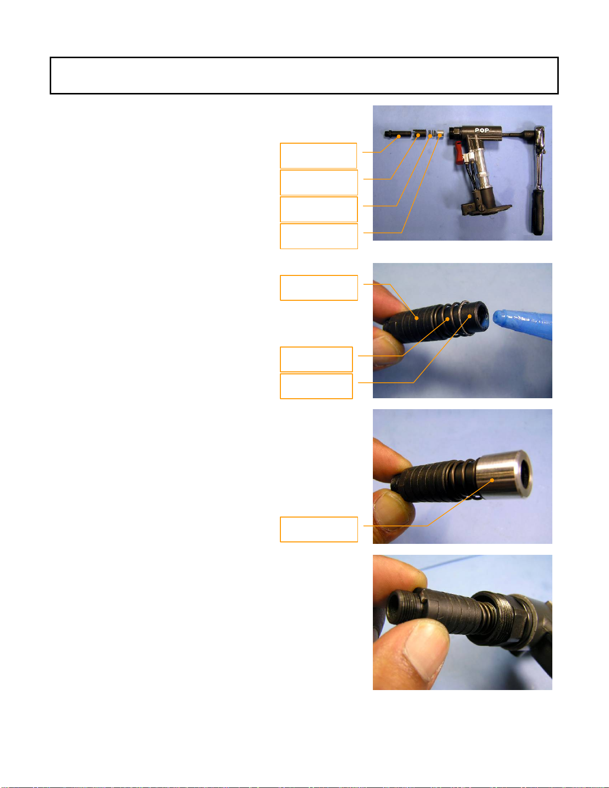
Chapter 7 – Jaws / Jaw Case
Insert a Jaw Pusher Spring(10) into a Pulling
Head(4).
Jaw Pusher Spring
Insert a Jaw Pusher(9) into the Pulling Head(4).
(10)
Jaw Pusher
Apply grease to inner circumference of a Jaw
Guide(3).
Grease: Three Bond 1901 Anti-seizing lubricant.
(9) (111)
Jaw Guide
Insert Jaws(2) into the Jaw Guide(3).
(3)
Jaw Guide
(3)
Jaws
(2)
Page 20 Emhart Teknologies - 50 Shelton Technology Center, Shelton CT 06484 - Tel. (203) 924-9341 - Fax (800) 225-5614
Other manuals for POP ProSet 1600 Series
1
This manual suits for next models
1
Table of contents
Other Emhart Teknologies Rivet Tools manuals


