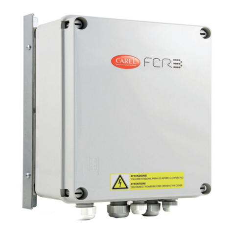
USER MANUAL TEMPERATURE CONTROLLER
STORM ST101 2HP
04
1.5. WIRING DIAGRAM
▶Connect the temperature sensor wires to terminals "1
and 2". There is no polarity. [2]
▶ Use terminals 9 and 11 to connect the controller to the
power supply voltage 85 to 250Vac or 9 a 36 V dc, according
to controller model.[3]
▶ Use terminals 15 and 16 to directly control a resistive load
for 2HP (NA relay - normally open)
[2] - In parameter P22 it is possible to choose the types of
temperature sensors.
[3] - The terminal 10 has no function, so it sh ould not be
used.
2.1. CONFIGURATION WITH
EMICOL APP
Access the Google Play to install the APP Emicol
Easy (see technical specifications in the table of item 1.3).
With the APP it’s possible:
▶Create countless configurations;
▶Send a configuration from the Cellphone to the Controller via
approximation;
▶Receive a configuration from the Controller to the Mobile via
approximation.
▶Share a configuration. For example, by WhatsApp;
▶Compare configurations and know their differences.
The ST101 2HP Controller can receive or send a configuration
even when disconnected from the power supply.
1.6. PRODUCT ASSEMBLY
The Controller must be installed in a space as
indicated in the table of item 1.3. Avoid installing in
places exposed to high humidity and dirt that can
cause condensation and the introduction of
substances or particles.
Make sure that the controller is installed in a
location that does not exceed the temperature limits
indicated in the table of item 1.3. The installation must
be as far away as possible from equipment that can
generate electromagnetic interference such as
motors, contactors, relays and solenoids.
2. ADJUSTMENT OF THE
PARAMETERS
The ST101 2HP Controller can be configured
by two different ways. Through the Emicol Easy
APP or directly through the front keys of the
controller.
The number of different adjustments with
Emicol Easy APP is unlimited. Depending only
on the memory capacity of the cell phone. The
ST101 controller can store only one configuration.
80,92
70
72,5
6,6
27,7 39,18
IMAGE 5
AC CONTROLLER
DC CONTROLLER
IMAGE 3
TEMPERATURE
SENSOR
ST101AC
215 1691 11
+
N
LOAD
UP TO 2HP N
POWER
GRID
90-250
VAC
+
IMAGE 4
TEMPERATURE
SENSOR
ST101DC
215 1691 11
+
N
LOAD
UP TO 2HP N
POWER
GRID
9-36
Vdc
+
+-+-
Note: The DC controller has polarity in the power signals. With the
inversion of the power signals, the controller will not work. If the DC
model is powered with AC voltage, it will burn the internal circuit of the
same, not being covered by the warranty.


