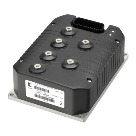
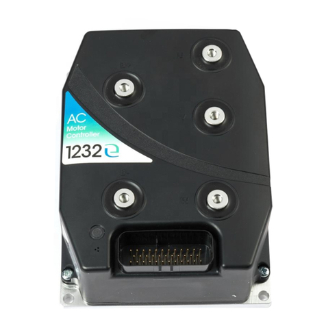
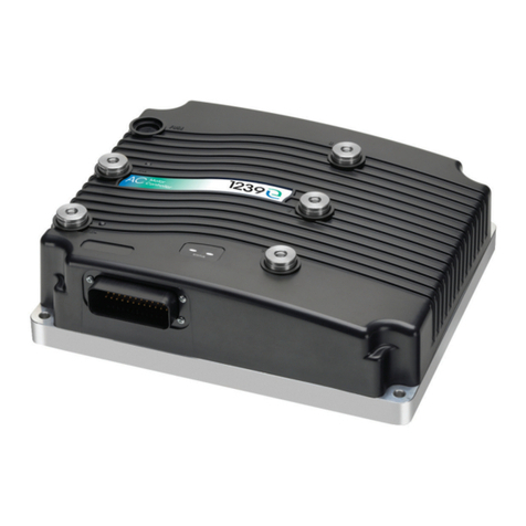
Curtis 1232E User manual

Manual
for Controller Models
1232E / 34E / 36E / 38E / 39E
and 1232SE / 34SE / 36SE / 38SE
Read Instructions Carefully!
Specications are subject to change without notice.
© 2016 Curtis Instruments, Inc. ® Curtis is a registered trademark of Curtis Instruments, Inc.
© The design and appearance of the products depicted herein are the copyright of Curtis Instruments, Inc. 53097 DD Supplement, os31 May 2017
Curtis Instruments, Inc.
200 Kisco Avenue
Mt. Kisco, NY 10549
www.curtisinstruments.com
» Software Version OS 31.0 «
DUAL DRIVE OPERATION

Curtis 1232E/34E/36E/38E/39E & 1232SE/34SE/36SE/38SE Manual, os 31 – May 2016
pg. ii
TABLE OF CONTENTS
CHAPTERS
1: OVERVIEW ...................................................................................................................................... 1
2: WIRING ........................................................................................................................................... 2
3: PROGRAMMABLE PARAMETERS ..................................................................................................... 5
4: DETERMINING CRITICAL ANGLE AND INNER WHEEL SPEED ............................................................. 9
5: DUAL DRIVE SETUP........................................................................................................................ 12
6: VEHICLE CONTROL LANGUAGE & CAN............................................................................................ 14
7: TROUBLESHOOTING....................................................................................................................... 18
TABLES
Table 1: Dual Drive Program Menus: 1311/1313 /1314 Programmer................................................... 5
Table 2: Dual Drive Troubleshooting Chart.......................................................................................... 20
FIGURES
Figure 1: Various Dual Drive vehicle congurations. ............................................................................ 1
Figure 2a: Wiring between the master and slave Dual Drive traction controllers. ................................. 2
Figure 2b: Basic wiring diagram for master controller, Dual Drive operation. ....................................... 3
Figure 2c: Basic wiring diagram for slave controller, Dual Drive operation........................................... 4
Figure 3: Typical 3-wheel Dual Drive vehicle geometry....................................................................... 10
Figure 4: Typical articulated steering Dual Drive vehicle geometry...................................................... 10
Figure 5: Ratio of inner-wheel speed to outer-wheel speed................................................................ 11
Figure 6: Inner-wheel and outer-wheel speed maps........................................................................... 11
Figure 7a: Motor command diagram, master controller. ..................................................................... 15
Figure 7b: Motor command diagram, slave controller......................................................................... 16

1—OVERVIEW pg. 1
1—OVERVIEW
e Dual Drive feature of Curtis 1232E/SE, 1234E/SE, 1236E/SE, 1238E/SE, and 1239E controllers
allows two controllers to work together in vehicles with dual xed-axle drive motors, a steered wheel
or axle, and an analog steer-angle sensor.
The two controllers must be the same size—for example, two 1234E-23XX controllers or two
1239E-65XX controllers. Non “E” controllers cannot be combined with “E” controllers.
e pair of controllers control motor speed on the inner and outer wheels during turns, as well as
vehicle speed and acceleration while turning. Current is automatically balanced between the two
traction motors when driving straight, and a limited operating strategy (LOS) allows limp-home in
case of a steer angle sensor or single motor or controller failure.
Figure 1 shows three typical Dual Drive vehicle congurations.
Dual Drive uses dierent speed maps for the two traction motors, one for the inner wheels and one
for the outer wheels. ese maps modify the throttle requests when the steering angle is outside the
10° deadband. Both are symmetrical around steer angle = 0°.
Figure 1
Various Dual
Drive vehicle
congurations.
Three-wheel:
Front-wheel steer:
Rear-wheel steer:
Return to TOC Curtis 1232E/34E/36E/38E/39E & 1232SE/34SE/36SE/38SE Manual, os 31 – May 2017

2 — WIRING
Curtis 1232E/34E/36E/38E/39E & 1232SE/34SE/36SE/38SE Manual, os 31 – May 2017 Return to TOC
pg. 2
2 — WIRING
One of the two controllers is designated the master and the other the slave. e master controller operates
the le motor and the slave operates the right motor. e throttle and brake inputs go to the master. e
steering pot input goes to the Pot2 input on the slave controller.
A single main contactor is used, and is controlled by the master. e KSI, CAN H, and CAN L pins of the
two controllers are connected together. B+ from the main contactor and the keyswitch are supplied to
each controller through separate pairs of fuses to enable operation to continue if one side fails. See Figure
2a, below, for an overview of the common wiring between the two controllers, and Figures 2b and 2c for
the detail in each controller.
Figure 2a
Wiring between the master and slave Dual Drive traction controllers.
SWITCH 2 /
ANALOG 2
J1-8
I/O GROUND J1-7
POT2 HIGH J1-27
POT2 WIPER J1-17
POT LOW J1-18
STEERING
POT
RIGHT
AC
MOTOR
J1-5
J1-13 KSI
COIL RETURN
BRAKE
J1-1 KSI
POSITION
FEEDBACK
DEVICE
J1-26
J1-31
J1-32
J1-7
J1-23
J1-35
J1-21
J1-34
Short for 120Ω
CAN bus termination
B+
V
+5V
FEEDBACK B
CAN TERM L
CAN L
U
W
FEEDBACK A
I/O GROUND
CAN TERM H
CAN H
RIGHT MOTOR
TEMP
SENSOR
SLAVE CONTROLLER
1232E/34E/36E/38E/39E
1232SE/34SE/36SE/38SE
B-
DRIVER 2
SWITCH 8
J1-33
REVERSE
SWITCH 7
J1-22
FORWARD
SWITCH 3
J1-9
INTERLOCK
SWITCH 2 /
ANALOG 2
J1-8
I/O GROUND
J1-7
THROTTLE
POT HIGH
J1-15
THROTTLE
POT WIPER
J1-16
POT2 HIGH
J1-27
POT2 WIPER
J1-17
POT LOW
J1-18
THROTTLE POT
BRAKE POT
LEFT
AC
MOTOR
MAIN
J1-5
J1-6
J1-13
DRIVER 2
DRIVER 1
KSI
COIL RETURN
MAIN
BRAKE
J1-1
KSI
J1-26
J1-31
J1-32
J1-7
J1-23
J1-35
J1-21
J1-34
Short for 120ΩΩ
CAN bus termination
BATTERY
(24–80V)
KEYSWITCH
B+
V
+5V
FEEDBACK B
CAN TERM L
CAN L
U
W
FEEDBACK A
I/O GROUND
CAN TERM H
B-
CAN H
LEFT MOTOR
TEMP
SENSOR
EMERGENCY
STOP
MASTER CONTROLLER
1232E/34E/36E/38E/39E
1232SE/34SE/36SE/38SE
POSITION
FEEDBACK
DEVICE
Note: See the 1239E manual for typical wiring for the external high-voltage
battery precharge circuit and for the 12V KSI and switch/driver I/O.

2 — WIRING pg. 3
Return to TOC Curtis 1232E/34E/36E/38E/39E & 1232SE/34SE/36SE/38SE Manual, os 31 – May 2017
e master controller is wired to all the components except those related to the Right motor and
the steering pot.
Figure 2b
Basic wiring diagram for master controller, Dual Drive operation.
SWITCH 16
J1-14
SWITCH 8
J1-33
REVERSE
SWITCH 7
J1-22
FORWARD
SWITCH 6
J1-12
SWITCH 5
J1-11
SWITCH 4
J1-10
SWITCH 3
J1-9
INTERLOCK
SWITCH 2 /
ANALOG 2
J1-8
J1-24
I/O GROUND
J1-7
THROTTLE
POT HIGH
J1-15
THROTTLE
POT WIPER
J1-16
POT2 HIGH
J1-27
POT2 WIPER
J1-17
POT LOW
J1-18
THROTTLE POT
BRAKE POT
LEFT
AC
MOTOR
MAIN
J1-2
J1-3
J1-4
J1-5
J1-6
J1-13
PROP. DRIVER
DRIVER 4
DRIVER 3
DRIVER 2
DRIVER 1
KSI
COIL RETURN
MAIN
BRAKE
J1-1
KSI
POSITION
FEEDBACK
DEVICE
J1-26
J1-31
J1-32
J1-7
J1-23
J1-35
J1-21
J1-34
Connect jumper for 120Ω
CAN bus termination
J1-25
J1-28
J1-29
J1-7
SERIAL PORT
(4-pin Molex)
4
3
1
2
CURTIS
MODEL 840
DISPLAY
8
6
5
BATTERY
(24–96V)
KEYSWITCH
B+
V
+5V
POSITION FEEDBACK B
CAN TERM L
CAN L
+12V
RX
I/O GROUND
U
W
POSITION FEEDBACK A
I/O GROUND
CAN TERM H
B-
CAN H
TX
LEFT MOTOR
TEMP
SENSOR
* 1232E and 1232SE do not include ANALOG OUT.
EMERGENCY
STOP
J1-30
J1-10
DIG. DRIVER 6
J1-20
DIG. DRIVER 7
to J1-23 on slave controller
to J1-35 on slave controller
to KSI (J1-1)on
slave controller
to B+ on
slave controller
MASTER CONTROLLER
1232E/34E/36E/38E/39E
1232SE/34SE/36SE/38SE
SWITCH 1 /
ANALOG 1
ANALOG OUT
(0–10V)
to B- on
slave controller
Note: KTY sensor shown.
The banded end must be
connected to I/O ground.
*
EMERG. REV.

2 — WIRING
Curtis 1232E/34E/36E/38E/39E & 1232SE/34SE/36SE/38SE Manual, os 31 – May 2017 Return to TOC
pg. 4
e slave controller is wired only to the Right motor and its encoder and temperature sensor, the
steering pot, CAN H, CAN L, KSI, B+/B–, and an electromagnetic brake.
Figure 2c
Basic wiring diagram for slave controller, Dual Drive operation.
SWITCH 2 /
ANALOG 2
J1-8
I/O GROUND J1-7
POT2 HIGH J1-27
POT2 WIPER J1-17
POT LOW J1-18
STEERING
POT
RIGHT
AC
MOTOR
J1-5
J1-13 KSI
COIL RETURN
BRAKE
J1-1 KSI
J1-26
J1-31
J1-32
J1-7
J1-23
J1-35
J1-21
J1-34
Short for 120Ω
CAN bus termination
J1-25
J1-28
J1-29
J1-7
SERIAL PORT
(4-pin Molex)
4
3
1
2
B+
V
+5V
POSITION FEEDBACK B
CAN TERM L
CAN L
+12V
RX
I/O GROUND
U
W
POSITION FEEDBACK A
I/O GROUND
CAN TERM H
CAN H
TX
RIGHT MOTOR
TEMP
SENSOR
to J1-23 on master controller
to J1-35 on master controller
to KSI (J1-1)on master controller
to B+ on master controller
SLAVE CONTROLLER
1232E/34E/36E/38E/39E
1232SE/34SE/36SE/38SE
SWITCH 16
SWITCH 8
SWITCH 7
SWITCH 6
SWITCH 5
SWITCH 4
SWITCH 3
SWITCH 1 / ANALOG 1
ANALOG OUT (0–10V)
J1-14
J1-33
J1-22
J1-12
J1-10
J1-9
J1-24
J1-30
B-
DRIVER 2
J1-2
J1-3
J1-4
J1-10
J1-20
PROP. DRIVER
DRIVER 4
DRIVER 3
DIGITAL DRIVER 6
DIGITAL DRIVER 7
to B- on master controller
J1-11
* 1232E and 1232SE do not include ANALOG OUT.
ANALOG OUT *
(0–10V)
J1-30
J1-6 DRIVER 1
THROTTLE
POT HIGH
J1-15
THROTTLE
POT WIPER
J1-16
Note: KTY sensor shown.
The banded end must be
connected to I/O ground.
POSITION
FEEDBACK
DEVICE

3 — PROGRAMMABLE PARAMETERS pg. 5
Return to TOC Curtis 1232E/34E/36E/38E/39E & 1232SE/34SE/36SE/38SE Manual, os 31 – May 2017
3 — PROGRAMMABLE PARAMETERS
e following programmable parameters are used to congure the Dual Drive feature. With only a
very few exceptions, all the parameters on both the master and the slave controller should be set to
the same values.
VCL is not required to operate in Dual Drive mode.
Table 1 Dual Drive Program Menus: 1311/1313 /1314 Programmer
DUAL DRIVE MENU............................ p. 6
— Dual Motor Enable
— Dual Motor Slave
— CAN Node ID Other
— LOS Max Speed
MASTER MENU.................................. p. 7
—Steer Angle Max
—Turn Accel Rate
—Critical Angle
—Max Turn Speed
—Inner Wheel Speed
—Steer Type
—Steer Pot Min
—Steer Pot Zero
—Steer Pot Max
—VCL Steer Enable
SLAVE MENU..................................... p. 8
—Turn Accel Rate
—Critical Angle
—Steer Fault Min
—Steer Fault Max
TURN FEEDFORWARD MENU............. p. 8
—Turn Accel Rate
—Turn Kvff
—Turn ff Build Rate
—Turn ff Release Rate
PARAMETER CHANGE FAULTS
Parameters marked PCF in the menu charts will set a Parameter Change Fault (code 49) if they are
changed while the motor bridge is enabled (interlock = On). Although the parameter will be changed,
the fault will prevent motor control functions until the fault is cleared by cycling the keyswitch. If
the motor bridge is disabled (interlock = O ), changing these parameters will not cause a fault and
the changes will take eect immediately.

3 — PROGRAMMABLE PARAMETERS
Curtis 1232E/34E/36E/38E/39E & 1232SE/34SE/36SE/38SE Manual, os 31 – May 2017 Return to TOC
pg. 6
DUAL DRIVE MENU
PARAMETER ALLOWABLE RANGE DESCRIPTION
Dual Motor Enable
|Dual_Motor_Enable
|OptionBits4 [Bit 2]
0x306D 0x00
On / Off
On / Off
To turn on the Dual Drive feature, set this parameter On in both controllers.
Dual Motor Slave
|Dual_Motor_Slave
|OptionBits4 [Bit 3]
0x306D 0x00
On / Off
On / Off
Set this parameter Off in the master controller and On in the slave controller.
CAN Node ID Other
Dual_CAN_Node_ID_Other
0x330F 0x00
1 – 127
1 – 127
The master and slave controllers must have different CAN Node IDs, and
each must know the CAN Node ID of the “other” controller so they can talk to
each other.
Set this parameter to the slave controller’s CAN Node ID in the master controller,
and set it to the master controller’s CAN Node ID in the slave controller.
LOS Max Speed
Dual_LOS_Max_Speed
0x38A2 0x00
100 – 8000 rpm
100 – 8000
Denes the maximum speed when a Dual Drive controller is running in LOS
(Limited Operating Strategy) mode.

3 — PROGRAMMABLE PARAMETERS pg. 7
Return to TOC Curtis 1232E/34E/36E/38E/39E & 1232SE/34SE/36SE/38SE Manual, os 31 – May 2017
DUAL DRIVE MASTER MENU
PARAMETER ALLOWABLE RANGE DESCRIPTION
Steer Angle Max (deg)
Dual_Steer_Angle_Max
0x38A3 0x00
45 – 90 deg
45 – 90
Set this to the maximum steer angle that is physically possible on the vehicle.
(Steer Angle is the angle-in-degrees that the steer wheel(s) "turn" from their
center/straight-ahead or zero-degree position)
Turn Accel Rate
Dual_Turn_Accel_Rate
0x38A8 0x00
0.1 – 30.0 s
100 – 30000
As the steering angle increases from the edge of the deadband to the
critical angle (Critical Angle), the acceleration rate is reduced linearly from
the normal value to the programmed Turn Accel Rate (see Figure 6). Higher
values represent slower acceleration.
This parameter appears in multiple places. Changing the value of this
parameter affects all parameters listed below:
Program » Dual Drive » Slave » Turn Accel Rate
Program » Dual Drive » Turn Feedforward » Turn Accel Rate
Critical Angle (deg)
Dual_Critical_Angle
0x38A6 0x00
45 – 90 deg
45 – 90
Set this parameter to the angle at which the vehicle pivots around its inner
wheel. Use the equation on page 9 to determine the critical angle.
This parameter appears in multiple places. Changing the value of this
parameter affects all parameters listed below:
Program » Dual Drive » Slave » Critical Angle (deg)
Max Turn Speed
Dual_Max_Turn_Speed
0x38A7 0x00
0 – 100 %
0 – 32767
As the steering angle increases from the edge of the deadband to the
maximum steer angle (Steer Angle Max), maximum speed is reduced
linearly from the normal value to the programmed Max Turn Speed
(see Figure 6).
Inner Wheel Speed
Dual_Inner_Wheel_Speed
0x38A9 0x00
–100.0 – 0.0 %
–32767 – 0
Set this parameter to the Inner wheel speed as a percentage of outer wheel
speed when the steer angle is 90 degrees. Use the equation on page 9 to
determine the appropriate percentage.
Steer Type PCF
Dual_Steer_Type
0x38AB 0x00
1 – 5
1 – 5
Set this parameter to the appropriate type for the steering pot you are using:
1. 2-wire rheostat, 5kΩ–0 input
2. Single-ended 3-wire 1kΩ–10kΩ potentiometer, 0–5V voltage source,
or current source
3. 2-wire rheostat, 0–5kΩ input
4. (not applicable)
5. VCL input (VCL_Steer).
NOTE: Do not change this parameter while the controller is powering the
motor. Any time this parameter is changed a Parameter Change Fault (fault
code 49) is set and must be cleared by cycling power; this protects the
controller and the operator.
Steer Pot Min
Dual_Steer_Pot_Min
0x38AC 0x00
0.00 – 6.25 V
0 – 32767
Set Steer Pot Min to the voltage on the steering pot when steering as far as
possible clockwise. Determine the value by reading the voltage on the pot
when steering CW to the maximum position.
Steer Pot Zero
Dual_Steer_Pot_Zero
0x38AD 0x00
0.00 – 6.25 V
0 – 32767
Set Steer Pot Zero to the voltage on the steering pot when steering
straight ahead. Determine the value by reading the voltage on the pot when
steering straight.
Steer Pot Max
Dual_Steer_Pot_Max
0x38AE 0x00
0.00 – 6.25 V
0 – 32767
Set Steer Pot Max to the voltage on the steering pot when steering as far as
possible counterclockwise. Determine the value by reading the voltage on
the pot when steering CCW to the maximum position.
VCL Steer Enable
|VCL_Steer_Enable
|VCL_Steer_Enable_Bit0 [Bit 0]
0x38A5 0x00
On / Off
On / Off
Setting this to On allows VCL to be used for additional steering processing.
3 — PROGRAMMABLE PARAMETERS
Curtis 1232E/34E/36E/38E/39E & 1232SE/34SE/36SE/38SE Manual, os 31 – May 2017 Return to TOC
pg. 8
DUAL DRIVE SLAVE MENU
PARAMETER ALLOWABLE RANGE DESCRIPTION
Turn Accel Rate
Dual_Turn_Accel_Rate
0x38A8 0x00
0.1 – 30.0 s
100 – 30000
As the steering angle increases from the edge of the deadband to the critical
angle (Critical Angle), the acceleration rate is reduced linearly from the
normal value to the programmed Turn Accel Rate (see Figure 6). Higher values
represent slower acceleration.
This parameter appears in multiple places. Changing the value of this
parameter affects all parameters listed below:
Program » Dual Drive » Master » Turn Accel Rate
Program » Dual Drive » Turn Feedforward » Turn Accel Rate
Critical Angle (deg)
Dual_Critical_Angle
0x38A6 0x00
45 – 90 deg
45 – 90
Set this parameter to the angle at which the vehicle pivots around its inner
wheel. Use the equation on page 9 to determine the critical angle.
This parameter appears in multiple places. Changing the value of this
parameter affects all parameters listed below:
Program » Dual Drive » Master » Critical Angle (deg)
Steer Fault Min
Dual_Steer_Fault_Min
0x38AF 0x00
0.00 – 5.50 V
0 – 28864
Sets the minimum threshold for the Dual Drive steering pot input. If the
steering pot voltage goes below this threshold, a Dual Severe Fault (75) will
be issued.
Steer Fault Max
Dual_Steer_Fault_Max
0x38B0 0x00
0.00 – 5.50 V
0 – 28864
Sets the minimum threshold for the Dual Drive steering pot input. If the
steering pot voltage goes below this threshold, a Dual Severe Fault (75) will
be issued.
DUAL DRIVE TURN FEEDFORWARD MENU
PARAMETER ALLOWABLE RANGE DESCRIPTION
Turn Accel Rate
Dual_Turn_Accel_Rate
0x38A8 0x00
0.1 – 30.0 s
100 – 30000
As the steering angle increases from the edge of the deadband to the critical
angle (Critical Angle), the acceleration rate is reduced linearly from the
normal value to the programmed Turn Accel Rate (see Figure 6). Higher values
represent slower acceleration.
This parameter appears in multiple places. Changing the value of this
parameter affects all parameters listed below:
Program » Dual Drive » Master » Turn Accel Rate
Program » Dual Drive » Slave » Turn Accel Rate
Turn Kvff
Dual_Turn_Kvff_SpdM
0x38B2 0x00
0 – 500 A
0 – 5000
This parameter can be used to improve the responsiveness of the traction
speed controller to changes in steer angle.
Turn ff Build Rate
Dual_Turn_ff_Build_Rate_SpdM
0x38B3 0x00
0.1 – 5.0 s
100 – 5000
Denes how quickly the Kvff term builds up.
Turn ff Release Rate
Dual_Turn_ff_Build_Rate_SpdM
0x38B4 0x00
0.1 – 2.0 s
100 – 2000
Denes how quickly the Kvff term releases. If the release seems too abupt,
slowing the release rate (i.e., setting this parameter to a higher value) will
soften the feel.

4 — DETERMINING CRITICAL ANGLE AND INNER WHEEL SPEED pg. 9
Return to TOC Curtis 1232E/34E/36E/38E/39E & 1232SE/34SE/36SE/38SE Manual, os 31 – May 2017
4 — DETERMINING CRITICAL ANGLE
AND INNER WHEEL SPEED
e rst step in setting up the Dual Drive feature is to determine the values of two parameters:
Critical Angle, the angle at which the vehicle pivots with its inner wheel stationary, and Inner Wheel
Speed, the desired inner-wheel speed at a 90° steer angle, expressed as a fraction of the outer-wheel
speed in this condition.*
4-WHEEL APPLICATIONS
Typically the Inner Wheel Speed = 0 for 4-wheel applications, as there should be no counter-rotation
with these vehicles. e Critical Angle is the angle at which the opposite wheels (front le and back
right, or front right and back le) are perpendicular to each other.
3-WHEEL APPLICATIONS
e Critical Angle and Inner Wheel Speed can be determined empirically or calculated using the
following equations, where W=wheelbase, T=track of the driven wheels, and A=distance between the
steered axle and the pivot point (see Figures 3 and 4). For vehicles without a steered axle, use A=0.
Any units can be used (feet, meters, etc.) as long as they are the same for all dimensions.
Critical Angle = 90 – arctan
= Answer in degrees; must be between 45° and 90°.
Inner Wheel Speed =
= Answer in %; must be between –100% and 0.
Example: For T=4, W=6, and A=1,
Critical Angle = 79° and Inner Wheel Speed = -33%.
*If your vehicle has a Steer Angle Max of less than 90°, you should still use the equation presented
here to calculate the proper value for Inner Wheel Speed. Measured inner wheel speed may be
quite dierent from the parameter value you set; this is normal. Use the calculated value as the
parameter setting.

4 — DETERMINING CRITICAL ANGLE AND INNER WHEEL SPEED pg. 11
Return to TOC Curtis 1232E/34E/36E/38E/39E & 1232SE/34SE/36SE/38SE Manual, os 31 – May 2017
e inner wheel speed is determined by the outer wheel speed, as shown in Figure 5. It decreases
from 100% of the outer wheel speed to zero at the programmed critical angle, and then from zero to
the programmed Inner Wheel Speed value at the maximum steering angle.
Figure 5
Ratio of inner-wheel speed to
outer-wheel speed, assuming a
90° maximum steering angle. 100%
Inner Wheel Speed
0
-100%
10°
90°
Critical Angle
STEERING ANGLE
speed of inner wheel = speed of outer wheel
Speed of inner wheel
Speed of outer wheel
Figure 6
Inner-wheel and outer-wheel
speed maps, assuming full
throttle.
Max Turn Speed
0
10°90°
Critical Angle
100%
-100%
STEERING ANGLE
Steering Angle Max
Inner Wheel Speed
Speed of outer wheel / Max Speed
Speed of inner wheel / Max Speed
e outer wheel speed is derived directly from the throttle request. As a result, the outer wheel speed
decreases linearly with the steering angle as shown in Figure 6.

5 — DUAL DRIVE SETUP
Curtis 1232E/34E/36E/38E/39E & 1232SE/34SE/36SE/38SE Manual, os 31 – May 2017 Return to TOC
pg. 12
5 — DUAL DRIVE SETUP
First you should complete the setup procedures for the two controllers you are using as outlined in the
1232E/34E/36E/38E/39E & 1232SE/34SE/36SE/38SE os31 manuals.. en proceed with these Dual Drive
setup procedures.
Before starting the Dual Drive setup procedures, jack the vehicle drive wheels up o the ground so that
they spin freely. Double-check all wiring to ensure it is consistent with the wiring guidelines presented in
Section 2. Make sure all connections are tight.
1 − Installation confirmation
Make sure that the master controller is connected to the Le motor, and the slave controller is connected
to the Right motor.
2 − Programming the master controller
e easiest method of programming is to set up the master rst, clone it to the slave, and then make
adjustments in the slave.
a. Set the master controller’s CAN Node ID in the CAN Interface menu to the master controller’s
unique ID.
b. Adjust the settings of the parameters in the Dual Drive menu:
• Set Dual Motor Enable = On.
• Set Dual Motor Slave = O.
• Set CAN Node ID Other = the slave controller’s CAN Node ID.
• Set LOS Max Speed to the desired value.
c. Adjust the settings of all the parameters in the Dual Drive Master menu.
d. Set the Interlock Type.
3 − Cloning the master controller to the slave controller
Use the 1313 handheld programmer or the 1314 PC Programming Station for cloning.
4 − Programming the slave controller
Aer cloning the master controller parameter settings to the slave controller, the following changes must
be made in the slave.
a. In the Dual Drive menu, set the slave controller’s Dual Motor Slave parameter to On.
b. In the CAN Interface menu, set the slave controller’s CAN Node ID to the slave controller’s
unique ID. Remember that this value must be the same as the Master’s CAN Node ID
Other parameter.
c. In the Dual Drive menu, set the slave controller’s CAN Node ID Other to the master controller’s
CAN Node ID.
CAUTION

5 — DUAL DRIVE SETUP pg. 13
Return to TOC Curtis 1232E/34E/36E/38E/39E & 1232SE/34SE/36SE/38SE Manual, os 31 – May 2017
d. If the same phase and encoder wiring conventions are used for the master and slave, set Swap
Two Phases and Swap Encoder Direction in the slave to values opposite those in the master (see
Motor menu).
e. Adjust the settings of the two parameters in the Dual Drive Slave menu as desired.
f. Set Interlock Type = 2, because the Slave’s interlock will be arriving over the CANbus.
5 − Setup confirmation
With the vehicle drive wheels still jacked up, apply interlock and throttle and verify that the wheels turn
at the proper speed and direction as the steer angle changes. If either wheel turns in the wrong direction
or appears to be “ghting itself ” (struggling at full current while jerkily turning at very low speed), try
changing the setting of the Swap Encoder Direction or Swap Two Phases parameters. (Refer to setup
procedures in the 1232E/34E/36E/38E/39E & 1232SE/34SE/36SE/38SE Manuals for help resolving encoder
issues.) If the motor still does not respond appropriately you should contact your Curtis customer support
engineer to resolve any issues before continuing.
Do not take the vehicle down o the blocks until the motors are responding properly.
CAUTION

6 — VEHICLE CONTROL LANGUAGE & CAN
Curtis 1232E/34E/36E/38E/39E & 1232SE/34SE/36SE/38SE Manual, os 31 – May 2017 Return to TOC
pg. 14
6 — VEHICLE CONTROL LANGUAGE & CAN
e motor command diagrams for the Dual Drive controllers are shown in Figure 7a (for the master
controller, which controls the Le traction motor) and Figure 7b (for the slave controller, which controls
the Right traction motor).
Dual Drive operation is initiated by the steer pot, which is connected to the slave controller. e steer pot
wiper voltage is sent in a CAN message to the master controller (Fig. 7a point A) where the wiper voltage
is converted to steer angle. e Steer_Angle and Mapped_rottle are processed and produce a throttle
value for the master traction controller and the slave traction controller (which is sent via a CAN message
to the slave controller (Fig. 7b point B).
e throttle processing in the master controller is similar to the throttle processing in a non-dual-drive
controller except for the additions of steer angle dual throttle processing and sending CAN messages to
the slave controller for throttle and brake commands. e brake signal can be followed in the master from
the brake pot input to the Brake_Command. e Dual_Slave_Brake_From_Master variable is sent from
the master traction controller to the slave traction controller via a CAN message (Fig. 7a point B to Fig.
7b point B).
e throttle processing in the slave controller is dierent from the throttle processing in a non-dual drive
controller because here the master controller is processing the throttle variables. e Dual_Slave_rottle_
From_Master (Fig. 7b point B) and Dual_Slave_Brake_From_Master (Fig. 7b point C) arrive from the
master as shown. e rottle Pot input on the slave is not used for throttle and may be programmed in
VCL for other uses.
VCL is not required to implement the Dual Drive CAN feature. Meaning that for a system not using
VCL, the dual drive master/slave controllers will operate as described above. However, when VCL is
implemented, should the VCL CAN operation be stop or become idle*, use the VCL function INIT_
DUAL_MOTOR_CAN() to restart (re-initialize) the Dual Drive CAN operation, besides using the
STARTUP_CAN() for VCL CAN.
INIT_DUAL_MOTOR_CAN( )
is function initializes (restarts) the dual drive CAN functions.
Syntax: Init_Dual_Motor_CAN()
Parameters: None.
Returns: None.
Error Codes: None.
*VCL functions that either stop or idle the VCL CAN operation will require re-initializing of the
dual drive CAN. Or, if the CANbus turns OFF or stops.
Examples:
1. e VCL function SETUP_CAN() in a VCL program will "stop" the Dual Drive CAN operation,
because it leaves the VCL CAN system in an idle state.
2. The VCL function SHUTDOWN_CAN () in a VCL program will stop the dual drive CAN
operation, because it stops the VCL CAN system.
3. If the variable can_error_status = 3, the CANbus is O (reference SysInfo, "CAN/Nodes Bus Status
Information" section).
NOTE: When using VCL with Dual Drive, the CAN mailboxes CAN3 – CAN6 are required to be
reserved by the OS for Dual Drive operation. Refer to the "CAN Access IDs" section in the SysInfo le.

6 — VEHICLE CONTROL LANGUAGE & CAN pg. 15
Return to TOC Curtis 1232E/34E/36E/38E/39E & 1232SE/34SE/36SE/38SE Manual, os 31 – May 2017
X++
Left
Motor
Control
Throttle Type
Reverse Switch
Forward Switch
Throttle Type
Processing
Forward Offset
Throttle Mapping
VCL_Throttle
Throttle_Multiplier
Throttle_Offset
OS Throttle
Throttle
Type = 5
or
VCL_
Throttle_
Enable = On
Throttle
Pot Raw
Forward Max
Forward Map
Forward Deadband
Reverse Deadband
Reverse Max
Reverse Map
Reverse Offset
Thr
ottle Command
Control Mode
Processing
Pot2 Raw
+100%
+100%
-100%
Throttle Type <4
and
Forward = Off
and
Reverse = On
and
TMap = 0
Throttle Type <4
and
Forward = On
and
Reverse = Off
and
TMap = 0
U Phase
W Phase
V Phase
Controller
Torque
Command
Control
Mode
Select = 0 or 1
and
Pump_ Enable_
SpdM = On
and
Mapped_
Throttle <0
Throttle_Command
Throttle
TMap
+1
-1
128
1 Brake_Command
Brake
Type
Brake Type
Processing
Brake
OS Brake
Brake Command
Brake Mapping
VCL_Brake
Brake Type = 5
or
VCL_Brake_
Enable = On
+100%
0%
FullBrake
Brake Max
Brake Offset
Brake Map
Brake Deadband
0%
Brake Pedal
Enable = On
Control
Mode
Select
= 0, 1, 2]
Mapped Throttle
Mapped Brake
ShutdownThrottle
or
ThrottleInvalid
or
Main Cont.
Not Closed
or
Interlock_State = Off
Steer Angle Max
Steer Angle Mapping
VCL_Steer
OS Steer
VCL Steer
Enable = On
or
Steer Type >3
Steer Type
Steer Pot Min
Steer Pot Zero
Steer Pot Max
Dual Throttle
Processing
Steer Pot Raw
ShutdownSteer
Dual_Slave_Throttle_from_Master
Dual_Master_Throttle_Command
0°
Steer Angle
Max Turn Speed
Critical Angle
Turn Accel Rate
Inner Wheel Speed
Dual Motor
Enable = On
and
Dual Motor
Slave = Off
CAN MISO
(CAN message
from slave
to master)
CAN MOSI
(CAN message
from master
to slave)
CAN MOSI
(CAN message
from master
to slave)
A
B
C
Dual_Slave_Brake_from_Master
Figure 7a
Motor command diagram, master controller.

6 — VEHICLE CONTROL LANGUAGE & CAN
Curtis 1232E/34E/36E/38E/39E & 1232SE/34SE/36SE/38SE Manual, os 31 – May 2017 Return to TOC
pg. 16
X++
Right
Motor
Control
Throttle Type
Reverse Switch
Forward Switch
Throttle Type
Processing
Forward Offset
Throttle Mapping
VCL_Throttle
Throttle_Multiplier
Throttle_Offset
OS Throttle
Throttle
Type = 5
or
VCL_
Throttle_
Enable = On
Throttle
Pot Raw
Forward Max
Forward Map
Forward Deadband
Reverse Deadband
Reverse Max
Reverse Map
Reverse Offset
Thr
ottle Command
Control Mode
Processing
+100%
-100%
Throttle Type <4
and
Forward = Off
and
Reverse = On
and
TMap = 0
Throttle Type <4
and
Forward = On
and
Reverse = Off
and
TMap = 0
U Phase
W Phase
V Phase
Controller
Torque
Command
Control
Mode
Select = 0 or 1
and
Pump_ Enable_
SpdM = On
and
Mapped_
Throttle <0
Throttle_Command
Throttle
TMap
+1
-1
128
1
Control
Mode
Select
= 0, 1, 2
Mapped Throttle
ShutdownThrottle
or
ThrottleInvalid
or
Main Cont.
Not Closed
or
Interlock_State = Off
Steer
Pot Raw
Dual_Slave_Throttle_from_Master
Steer
Angle
Pot
CAN MOSI
(CAN message
from master
to slave)
Dual Motor
Enable = On
and
Dual Motor
Slave = On
CAN MISO
(CAN message
from slave
to master)
Brake Command
CAN MOSI
(CAN message
from master
to slave)
Dual_Slave_Brake_from_Master
C
B
A
Figure 7b
Motor command diagram, slave controller.

6 — VEHICLE CONTROL LANGUAGE & CAN pg. 17
Return to TOC Curtis 1232E/34E/36E/38E/39E & 1232SE/34SE/36SE/38SE Manual, os 31 – May 2017
CAN
e CAN messages indicated by the A, B, and C points in Figures 7a and 7b are shown in the byte maps
below, along with the additional variables that are available (and CAN Index) to Dual Drive applications.
PDO3 MOSI Byte Map (Sent by the master to the slave).
MOSI is RX in CANopen nomenclature
BByte 1 = Dual_Slave_Throttle_from_Master (high byte) 0x38B6 0x00
Slave throttle command from master.
B Byte 2 = Dual_Slave_Throttle_from_Master (low byte) 0x38B6 0x00
Byte 3 = Steer_Type_Master
Steer Type parameter setting from master;
used to set up proper pot type in the slave.
Byte 4 = [Not used]
Byte 5 = Flags_Master 0x38BC 0x00
Used to synchronize inputs and outputs between master and slave.
Byte 6 = [Not used]
Byte 7 = [Not used]
C Byte 8 = Dual_Slave_Brake_from_Master 0x38B5 0x00
Slave brake command from master.
PDO3 MISO Byte Map (Sent by the slave to the master). MISO is TX in CANopen nomenclature
A Byte 1 = IqReq_Slave (high byte)
Used to balance the current load between master and slave.
A Byte 2 = IqReq_Slave (low byte)
Byte 3 = [Not used]
Byte 4 = [Not used]
Byte 5 = Flags_Slave 0x38BD 0x00
Used to synchronize inputs and outputs between master and slave.
Byte 6 = [Not used]
A Byte 7 = Steer_Pot_Raw (high byte) 0x38BB 0x00
Voltage from steer pot for master to use in calculating steer angle.
A Byte 8 = Steer_Pot_Raw (low byte) 0x38BB 0x00
e contents of Flags_Slave and Flags_Master are as follows:
Bit1 = Dual_Motor_Interlock_Bit
Used to synchronize the interlock between master and slave.
Bit2 = Request_Dual_Motor_Interlock_Bit
Used to request the interlock between master and slave.
Bit3 = EM_Brake_Ready_To_Set
Used to synchronize the EM brake between master and slave.
Bit4 = LOS_Speed_Flag
Used to initiate LOS speed in the other traction controller.
Bit5 = Main_Sync_Flag
Used to synchronize the Main Contactor states between master
and slave.
Bit6 = Main_Closed_Flag
Used to synchronize the Main Contactor “is closed” between master
and slave.
Bit7 = LOS_Clear_Flag
Used to clear LOS speed in the other traction controller.
Bit8 = Precharge_Sync_Master_Flag
Used to synchronize the precharge between master and slave
e contents of Flags_Slave_More and Flags_Master_More are as follows:
Bit5 = Dual_Motor_EM_Brake_Throttle_Flag
Used to synchronize the EM Brake and Throttle between master
and slave.
Bit6 = Dual_Motor_Ready_To_Enter_Position_Hold_Flag
Used to synchronize the Position Hold between master and slave.
Bit7 = Dual_Motor_In_Position_Hold_Flag
Used to synchronize Position Hold between the master and slave.
Bits 1-4, 8 = [Not used]

7 — TROUBLESHOOTING
Curtis 1232E/34E/36E/38E/39E & 1232SE/34SE/36SE/38SE Manual, os 31 – May 2017 Return to TOC
pg. 18
7 — TROUBLESHOOTING
With Dual Drive systems there are two traction controllers, and when faults occur they usually aect both
of the controllers.
e Dual Drive Troubleshooting Chart (Table 2) is written from the perspective of the controller that is
issuing the fault. e eects on the other controller are shown as well.
DUAL DRIVE LIMITED OPERATING STRATEGY
When the Dual Drive Limited Operating Strategy (LOSDual) is initiated, the controller’s motor(s)-speed
will be clamped to the parameter LOS Max Speed setting (VCL parameter name Dual_LOS_Max_Speed),
see page 6. en, if the rottle Command (see the Monitor»Inputs menu in the controller's manual,
and 1313/1314) results in the motor-speed request exceeding the LOS Max Speed, the motor rpm will be
clamped to the LOS Max Speed, subject to normal slewing constraints.
If the steer angle input is invalid, both controllers will use the Dual Drive's LOS Max Speed and assume that
the steer angle is 0 degrees (also see the Monitor»Inputs menu in the controller's manual, and 1313/1314).
If the motor encoder is invalid on only one side (i.e., master or slave controller), that controller will have
its bridge disabled, and the other controller will use the LOS Max Speed and assume that the steer angle is
0 degrees. If both encoder signals are invalid, the vehicle will not drive. (see Codes 36 and 73 in Table 2).
Other manuals for 1232E
4
This manual suits for next models
8
Table of contents
Other Curtis Controllers manuals

Curtis
Curtis MultiMode 1228 User manual

Curtis
Curtis 1232E User manual

Curtis
Curtis 1232E User manual

Curtis
Curtis 1268-5403 User manual

Curtis
Curtis 1212S User manual

Curtis
Curtis 1204M User manual

Curtis
Curtis 1212 User manual

Curtis
Curtis 1253 User manual

Curtis
Curtis 1268 User manual

Curtis
Curtis 1239E User manual

Curtis
Curtis 1313 User manual

Curtis
Curtis PMC 1204 Series User manual

Curtis
Curtis 1297 User manual

Curtis
Curtis 1232E User manual

Curtis
Curtis 1268 User manual

Curtis
Curtis MultiMode 1207B User manual

Curtis
Curtis 1232E User manual

Curtis
Curtis 1244 User manual

Curtis
Curtis 1310 User manual

Curtis
Curtis 1298 User manual