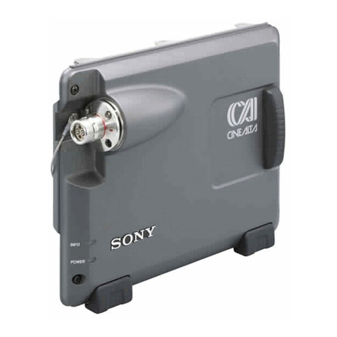
Sony LMT-100 User manual

3-992-365-02 (2)
Media Block
特約店様用設置説明書 2 ページ ______________________________
Installation Manual for Dealers Page 14_______________________
この特約店様用設置説明書には、接続例やインプットボードの取り付けなど、製品の設置
時に必要な情報を記載しています。
電気製品は安全のための注意事項を守らないと、
火災や人身事故になることがあります。
この設置説明書には、事故を防ぐための重要な注意事項と製品の取り扱いかたを示していま
す。この設置説明書をよくお読みのうえ、製品を安全にお使いください。
お読みになったあとは、いつでも見られるところに必ず保管してください。
This manual gives the necessary information for installation of this product, such as
connection examples and attachment of an optional input board.
© 2006 Sony Corporation
警告
このマニュアルはサービス専用です。
お客様が、このマニュアルに記載された設置や保守、点検、修理などを行うと感電や
火災、人身事故につながることがあります。
危険を避けるため、サービストレーニングを受けた技術者のみご使用ください。
WARNING
This manual is intended for qualified service personnel only.
To reduce the risk of electric shock, fire or injury, do not perform any servicing
other than that contained in the operating instructions unless you are qualified to
do so. Refer all servicing to qualified service personnel.
LMT-100
JP
GB

2
安全のために
ソニー製品は安全に充分配慮して設計されています。しかし、電気製品はまち
がった使いかたをすると、火災や感電などにより死亡や大けがなど人身事故につ
ながることがあり、危険です。
事故を防ぐために次のことを必ずお守りください。
安全のための注意事項を守る
4 ページから 5 ページの注意事項をよくお読みください。
定期点検を実施する
1 年に一度は、内部の点検をお買い上げ店またはソニーのサービス窓口にご依頼
ください(有料)。
故障したら使わない
すぐにお買い上げ店またはソニーのサービス窓口にご連絡ください。
万一、異常が起きたら
m
a電源を切る。
b電源コードや接続コードを抜く。
cお買い上げ店またはソニーのサービス窓口に連絡する。
m
すぐに電源を切り、消火する。
•煙が出たら
•異常な音、においがしたら
•内部に水、異物が入ったら
•製品を落としたりキャビネットを破損したときは
炎が出たら
警告表示の意味
取扱説明書および製品では、次の
ような表示をしています。表示の
内容をよく理解してから本文をお
読みください。
この表示の注意事項を守らないと、
火災や感電などにより死亡や大け
がなど人身事故につながることが
あります。
この表示の注意事項を守らないと、
感電やその他の事故によりけがを
したり周辺の物品に損害を与えた
りすることがあります。
注意を促す記号
行為を禁止する記号
行為を指示する記号
日本語

3
目次
JP
目次
警告.....................................................................4
注意.....................................................................5
システムの構成例......................................................6
ラックに取り付ける ..................................................7
インプットボードを取り付ける ................................8
接続する ....................................................................9
SR プロジェクターを接続する ............................9
コントロール用コンピューターを接続する ......10
RAID ディスクを接続する ................................10
オーディオシグナルプロセッサーを接続する...11
本機の性能を保持するために..................................11
寸法図......................................................................12

4警告
指定された電源コードを使
用する
指定以外の電源コードを使用すると、
火災や感電の原因となります。
電源コードのプラグおよび
コネクターは突き当たるま
で差し込む
まっすぐに突き当たるまで差し込ま
ないと、火災や感電の原因となりま
す。
電源コードを傷つけない
電源コードを傷つけると、火災や感
電の原因となることがあります。
•設置時に、製品と壁やラック、棚な
どの間に、はさみこまない。
•電源コードを加工したり、傷つけた
りしない。
•重いものをのせたり、引っ張ったり
しない。
•熱器具に近付けたり、加熱したりし
ない。
•電源コードを抜くときは、必ずプラ
グを持って抜く。
万一、電源コードが傷んだら、お買
い上げ店またはソニーのサービス窓
口に交換をご依頼ください。
油煙、湯気、湿気、ほこり
の多い場所では設置、使用
しない
上記のような場所や、取扱説明書に
記されている仕様条件以外の環境で
使用すると、火災や感電の原因とな
ることがあります。
専用ブレーカまたはスイッ
チを設ける
本機には、電源スイッチがあります
が、ラックマウント設置の際には、
本機の近くの容易に接近できる屋内
配線内に専用ブレーカやスイッチを
設けるか、または本機の使用中でも
容易に抜き差しできるコンセントに
電源プラグを接続してください。
万一、異常が生じた場合は、専用ブ
レーカやスイッチを OFF にするか、
電源プラグを抜いてください。

5
注意
強度を満足したラックマウント
レールを使用する
ラック取り付け方法の耐荷重を満たし、
取り付け穴に合うラックレールを使って
ください。レールの強度不足があると、
機器が落下してけがをすることがありま
す。
安全アースを接続する
安全アースを接続しないと、感電するこ
とがあります。
指定の電源コードを使用することで安全
アースが接続されます。
機器や部品の取り付けは正しく
行う
機器のラックアングルのネジを締め忘れ
ると、機器がラックから滑り出し、落下
することがあります。
安定した場所に設置する
製品が倒れたり、搭載した機器が落下し
てけがをすることがあります。十分な強
度がある水平な場所に設置してください。
通気孔をふさがない
通気孔をふさぐと内部に熱がこもり、火
災や故障の原因となることがあります。
風通しをよくするために次の項目をお守
りください。
•壁から 10cm 以上離して設置する。
•密閉された狭い場所に押し込めない。
•毛足の長い敷物(じゅうたんや布団な
ど)の上に設置しない。
•布などで包まない。
•あお向けや逆さまにしない。
ラックマウントは 2 人以上で
行う
本機をラックにマウントするときは、必
ず 2 人以上で行ってください。1 人で行う
と、腰を痛めることがあります。
重い製品の運搬は 2 人以上で
行う
本機は重量物ですので、1人で運搬する
と腰を痛めたり、けがをすることがあり
ます。
運搬するときは指定された場所
を持つ
運搬するときは底板を持ってください。
そうでないと本機が落下してけがをする
ことがあります。
2 台以上積み上げない
ラックを使用せずに 2 台以上積み上げる
と、機器が落下してけがをすることがあ
ります。
ラックに確実に固定する
不安定な場所に置くと本機の落下や転倒
でけがの原因となることがあります。

システムの構成例
6
システムの構成例
メディアブロック LMT-100 は、SR プロジェクター SRX-R110 または SRX-R105 と組み合わせて、デジタルシネマの上映を可
能にする劇場内のサーバーです。
下図の基本的な構成例では以下のことができます。
•デジタルシネマで配信される DCP(DigitalCinemaPackage)に含まれる映像ファイルを、SMS(ScreenManagement
System)ソフトウェアを搭載したコンピューターを介して SR プロジェクターに映像信号として出力します。
•映像に同期したデジタルオーディオ信号をオーディオシグナルプロセッサーに出力します。
•本機と光ファイバーケーブルで接続した RAID ディスクに DCP を格納します。
•別売のインプットボードを装着し、外部機器から HD-SDI 信号などを入力してそのまま SR プロジェクターに出力します。
*以下のケーブルをご使用ください。
1000BASE-T 通信時:カテゴリー 5E 以上の UTP または STP ケーブル
100BASE-TX 通信時:カテゴリー 5 以上の UTP または STP ケーブル
,
IN OUT
DCP
SMS 搭載のコンピューター SRX シリーズ SR プロジェクター
PM-Link ケーブル
(付属)
メディアブロック
LMT-100 光ファイバー
ケーブル
RAID ディスク
オーディオシグナル
プロセッサー
イーサネットケーブル *
AES/EBU
ケーブル
信号の流れ
HDCAM-SR レコーダー /
プレーヤーなど
HD-SDI

ラックに取り付ける 7
ラックに取り付ける
本機をラックなどに取り付ける場合は、付属のラックアン
グルを左右側面に取り付けます。
ラックに取り付けるスライドレールは、定格荷重 539N/ ペ
ア以上のものを使用してください。
◆ 本機の寸法については、「寸法図」(12 ページ)をご覧くださ
い。
◆ 詳しくは、ご使用になるラックの取付説明書をご覧ください。
1
必要に応じて本機底面の脚(4 か所)を取りはずす。
2
ラックアングルを付属のネジ2本ずつで本機に取り付け
る。
ラックアングルの後側のネジ穴をご使用ください。
3
ラックに取り付ける。
本機側面に取り付けてあるネジ(左右 4 本ずつ)をご
使用ください。
•取り付け穴の位置が本機に合うスライドレールを使用し
てください。
•ネジは締め付けトルク 1.4 ± 0.2N·m で締めてください。
ご注意

インプットボードを取り付ける
8
インプットボードを取り
付ける
本機の外部入力スロットに別売のインプットボードを装着
することにより、外部出力装置からの信号を入力できます。
本機に装着できるインプットボードは 1 枚です。
1
インプットボード取り付け部のネジ 2 本をゆるめ、目か
くし板を取りはずす。
2
インプットボードをレールに沿って差し込む。
3
ネジ 2 本を締める。
締め付けトルク 0.8 ± 0.1N·m でしっかり締めてくださ
い。
はずすときは、ネジ 2 本を確実にゆるめて引き抜きま
す。
ご注意
OUT
IN
OUT
IN

接続する 9
接続する
接続するときは
•各機器の電源を切った状態で接続してください。
•接続ケーブルは、それぞれの端子に合った正しいものを
選んでください。
•プラグはしっかり差し込んでください。抜くときは、必
ずプラグを持って抜いてください。
◆ 接続する機器の取扱説明書もあわせてご覧ください。
SR プロジェクターを接続する
本機に付属の基板を、SR プロジェクターに
取り付ける
本機に付属のプロジェクター用インプットボード 2 枚を、
プロジェクター左側面のインプットボード取り付け部の一
番上(INPUTA)と二番目(INPUTB)に取り付けます。
インプットボードの取り付けかたは、別売のインプット
ボードを本機に取り付ける場合と同じです。「インプット
ボードを取り付ける」(8 ページ)をご覧ください。
◆ SRX-R110/R105 の特約店様用設置説明書もあわせてご覧くださ
い。
本機に SR プロジェクターを接続すると、SR プロジェク
ターのインプットボード取り付け部の 3 番目と 4 番目には
インプットボードを装着できません。
本機に付属のケーブルを接続する
本機に付属の PM-Link ケーブルで、本機の OUTPUTA 端
子とプロジェクターの INPUTA 端子、本機の OUTPUTB
端子とプロジェクターの INPUTB 端子を接続してくださ
い。
コネクターカバーを取り付ける
ケーブルのコネクター保護のため、本機の OUTPUTA 端
子と OUTPUTB 端子に接続したケーブルのコネクターに、
付属のコネクターカバーを取り付けてください。
コネクターカバーをコネクターに取り付け、付属のネジ 5
本で締めます。
ご注意
IN OUT
IN OUT
INTER LOCK
ETHERNET RS232C
SR プロジェクター SRX-R110/R105
本機後面
INPUTA 端子へ INPUTB 端子へ
抜くときは、左
右を押しながら
いったん押し込
んでから抜く。
PM-Link ケーブル
(付属)
OUTPUTA 端子 OUTPUTB 端子
ネジ(5 本)
(付属)
コネクターカバー(付属)

接続する
10
コントロール用コンピューターを接続
する
SMS(ScreenManagementSystem)ソフトウェアを搭載
したコンピューターとイーサネットケーブルで接続します。
注意
安全のために、周辺機器を接続する際は、過大電圧を持つ
可能性があるコネクターをこの端子に接続しないでくださ
い。
接続については本書の指示に従ってください。
RAID ディスクを接続する
RAID ディスクはソニーが推奨するものをご使用ください。
◆ 推奨品について詳しくは、お買い上げ店またはソニーのサービ
ス窓口にお問い合わせください。
光ファイバーケーブルの曲げ部分は半径 30mm 以上確保し
て固定してください。
SMS 搭載コントロール用
コンピューター
本機前面
ETHERNET 端子
イーサネットケーブル
Ethernet
端子へ
ご注意
本機前面
光ファイバー
ケーブル
FIBRE
CHANNEL 端子
RAID ディスク

本機の性能を保持するために 11
オーディオシグナルプロセッサーを接
続する
接続するオーディオシグナルプロセッサーの入力端子によ
り、AUDIOOUTPUT(AES/EBU) 端子の D-sub25 ピンま
たは BNC 端子に接続します。
出荷時の設定では、D-sub25 ピン型と BNC 型端子から、
チャンネル 1 からチャンネル 8 の AES/EBU デジタルオー
ディオ信号が出力されます。(同じ信号が出力されます。)
SMS 搭載のコンピューターの設定により、D-sub25 ピン型
端子から、チャンネル 9 からチャンネル 16 の信号を出力す
ることもできます。
本機の性能を保持するた
めに
お手入れについて
キャビネットやパネルの汚れは、柔らかい布で軽くふき
取ってください。汚れがひどいときには、水でうすめた中
性洗剤に柔らかい布をひたし、固くしぼってから汚れをふ
き取り、乾いた布で仕上げてください。なお、お手入れの
際は必ず電源コードを本体から抜いてください。
結露について
結露とは、寒いところから急に暖かい場所へ持ち込んだと
き、本体の内部に水滴がつくことです。結露が起きたとき
は、電源を入れたまま本機をそのまま約 2 時間放置してお
いてください。
本機前面
AUDIO
OUTPUT
(AES/EBU)
(BNC)端子へ
AUDIOOUTPUT
(AES/EBU)
(D-sub25 ピン)
端子へ
D-sub25 ピン
ケーブル
BNC ケーブル
オーディオシグナルプ
ロセッサー
音声入力へ 音声入力へ

寸法図
12
寸法図
前面(ラックアングル装着時)
単位:mm
側面
単位:mm
上面(コネクターカバー装着時)
単位:mm
482
424
37.7
177
22113.9
465
332
101.6
86.7
7
57.5
( 120)
(70)
184
111.1
88.5
349.3
225.4
352.4
454.9
1) ラックマウント用ネジ穴(左右側面)
2) 光ファイバーケーブルの曲げ部分は半径 30mm 以上
必要です。
3) ご使用時、半径 120mm 以上のスペースが必要です。
PM-Link ケーブル 3)
光ファイバーケーブル 2)
8-M41)
7
498.5
454.9
28.5
6275 PM-Link ケーブル
コネクターカバー


14 Table of Contents
Table of Contents
Precautions................................................15
System Configuration ...............................16
Installing on a Rack...................................17
Attaching an Input Board .........................18
Connections...............................................19
Connecting the SR Projector ...................... 19
Connecting a Computer for Controlling ..... 20
Connecting a RAID Storage Disk............... 20
Connecting an Audio Signal Processor ...... 21
Dimensions ................................................21
English

Precautions 15
GB
Precautions
On safety
• Operate the unit on 100 – 240 V AC, 50/60 Hz.
• Should any liquid or solid object fall into the cabinet,
unplug the unit and have it checked by qualified Sony
personnel before operating it further.
• Unplug the unit from the wall outlet or turn off the power
switches on the front and rear of the unit if it is not to be
used for several days.
• To disconnect the cord, pull it out by the plug. Never pull
the cord itself.
• The wall outlet should be near the unit and easily
accessible.
• The unit is not disconnected from the AC power source
(mains) as long as it is connected to the wall outlet and
the main power switch is turned on.
• Do not place your hand or objects near the ventilation
holes. The air coming out is hot.
• Have at least two people carry and handle the unit, to
avoid accidents or injury.
• Avoid using an extension cord with a low voltage limit,
as it may cause short-circuiting and physical injury.
• To carry the unit, be sure to hold the bottom of the unit.
• Do not catch your finger between the unit and surface of
the floor when moving the unit installed on the floor.
• Be careful not to catch your finger in the cooling fan.
On installation
• Allow adequate air circulation to prevent internal heat
build-up. Do not place the unit on surfaces (rugs,
blankets, etc.) or near materials (curtains, draperies) that
may block the ventilation holes. Leave space of more
than 10 cm (4 inches) between the wall and the unit. Be
aware that room heat rises to the ceiling; check that the
temperature near the installation location is not
excessive.
• Do not install the unit in a location near heat sources
such as radiators or air ducts, or in a place subject to
direct sunlight, excessive dust or humidity, mechanical
vibration or shock.
• To avoid moisture condensation, do not install the unit in
a location where the temperature may rise rapidly.
Caution
The projector is equipped with ventilation holes (intake) at
the upper, left and right sides, and ventilation holes
(exhaust) at the rear side.
Do not block or place anything near these holes, or internal
heat build-up may occur, causing damage to the unit.
On cleaning
To keep the cabinet looking new, periodically clean it with
a soft cloth. Stubborn stains may be removed with a cloth
lightly dampened with a mild detergent solution. Never
use strong solvents, such as thinner, benzene, or abrasive
cleansers, since these will damage the cabinet.
On repacking
Save the original shipping carton and packing material;
they will come in handy if you ever have to ship your unit.
For maximum protection, repack your unit as it was
originally packed at the factory.

16 System Configuration
System Configuration
The LMT-100 Media Block is a server located in a theater that offers the capability of digital cinema exhibition in
combination with the SRX-R110 or SRX-R105 SR projector.
The system configuration example described below allows you to:
• Input the video files included in the DCP (Digital Cinema Package) for digital cinema distribution and to output digital
video signals to the SR projector via a computer with SMS (Screen Management System) application software installed.
• Output digital audio signals to an audio signal processor in synchronization with digital video signals.
• Store the DCP in an external RAID storage disk connected to the unit with a commercially available optical fiber cable.
• Input an HD-SDI signal, etc. from external equipment and output it to the SR projector if the optional input board is
installed in the unit.
* Use the following cables:
• UTP or STP cable of category 5E or higher for communication via 1000BASE-T
• UTP or STP cable of category 5 or higher for communication via 100BASE-TX
,
IN OUT
SRX series SR projector
Computer with SMS installed
PM-Link cables
(supplied)
DCP
Ethernet cable*
AES/EBU cable
Audio signal processor
HDCAM-SR recorder/
player, etc.
Signal flow
RAID storage disk
Optical fiber cable
LMT-100 Media
Block
HD-SDI

17
Installing on a Rack
Attach the supplied angle brackets to the left and right
sides of the unit to install it on a rack.
The slide rails to be used with the rack should have a rated
load of more than 539 N in pair.
For the dimensions of the unit, see “Dimensions” on page
21.
For more information, refer to the instruction manual of
the rack you are using.
1
Remove the four legs from the bottom of the unit, if
necessary.
2
Attach the supplied angle brackets with the supplied
two screws for each side.
Use a screw hole on the rear of the bracket.
3
Install the unit on the rack.
Use the four screws removed from each of the left and
right sides of the unit.
• Use the slide rails whose attachment screw holes fit the
screw holes on this unit.
• Tighten the screws with a torque of 1.4±0.2 N•m.
Notes

18 Attaching an Input Board
Attaching an Input Board
Attaching an optional input board to the input board slot on
the unit allows input of a signal source from external
equipment.
One input board can be installed in the unit.
1
Loosen the two screws fully and remove the panel on
the input board slot.
2
Push in the input board along the rails.
3
Tighten the two screws firmly with a torque of 0.8±0.1
N•m.
To remove the input board, loosen the two screws fully and
pull it out.
Note
OUT
IN
OUT
IN

19
Connections
Connections
When you connect the unit, be sure to:
• Turn off all equipment before making any connections.
• Use the proper cables for each connection.
• Insert the cable plugs firmly. When pulling out a cable,
be sure to pull it out holding the plug, not the cable itself.
Refer also to the instruction manuals of the equipment to
be connected.
Connecting the SR Projector
Attaching the supplied input boards to the
SR projector
Attach the supplied two PM input boards to the top
(INPUT A) and second (INPUT B) input board slots on the
left side of the projector. The attachment procedure is the
same as in the case of attaching the optional input board to
the unit. See “Attaching an Input Board” on page 18.
Refer also to the Installation Manual for Dealers of the
SRX-R110/R105 SR projector.
When this unit is connected to an SR projector, you cannot
install any input board in the third and fourth input board
attachment parts on the SR projector.
Connecting the supplied PM-Link cables
Using the supplied PM-Link cables, be sure to connect the
OUTPUT A connector on the unit to the INPUT A
connector on the projector, and the OUTPUT B connector
to the INPUT B connector.
Attaching the connector cover
The unit is supplied with a connector cover to protect the
connectors of the PM-Link cables.
Attach the connector cover to the two connectors of the
cables inserted into the OUTPUT A and OUTPUT B
connectors on the rear of the unit using the supplied five
screws.
Note
IN OUT
IN OUT
INTER LOCK
ETHERNET RS232C
SRX-R110/R105 SR projector
Rear of the
LMT-100
to INPUT B
to INPUT A
PM-Link cables
(supplied) To remove,
push in while
pressing both
sides, and then
pull out the
connector.
OUTPUT BOUTPUT A
Screws (5)
(Supplied)
Connector cover

20 Connections
Connecting a Computer for
Controlling
Connect a computer with SMS (Screen Management
System) application software installed to the unit with a
commercially available Ethernet cable.
CAUTION
For safety, do not connect the connector for peripheral
device wiring that might have excessive voltage to this
port.
Follow the instructions for this port.
ATTENTION
Par mesure de sécurité, ne raccordez pas le connecteur
pour le câblage de périphériques pouvant avoir une tension
excessive à ce port. Suivez les instructions pour ce port.
ACHTUNG
Aus Sicherheitsgründen nicht mit einem Peripheriegerät-
Anschluss verbinden, der zu starke Spannung für diese
Buchse haben könnte. Folgen Sie den Anweisungen für
diese Buchse.
Connecting a RAID Storage Disk
Use a RAID storage disk recommended by Sony.
For details on recommended products, contact Qualified
Sony Service Personnel.
Do not bend the optical fiber cable to a radius of less than
30 mm (1 3/16 inches).
Computer with SMS installed
Front of the LMT-100
ETHERNET
Ethernet cable
To Ethernet
connector
Note
Front of the LMT-100
FIBRE
CHANNEL
Optical fiber cable
RAID storage disk
Other manuals for LMT-100
2
Table of contents
Languages:
Other Sony Media Converter manuals

Sony
Sony LMT-100 User manual

Sony
Sony BKMA-7031 User manual

Sony
Sony PCWA-DE80 Read This First Instruction sheet

Sony
Sony DVMC-DA2 User manual

Sony
Sony BKSR-2025 User manual

Sony
Sony MVS-8000X System User manual

Sony
Sony GIGAJUKE NAS-C5E User manual

Sony
Sony DFP-R3000 User manual

Sony
Sony BKPF-101A User manual

Sony
Sony DSBK-1820 User manual
Sony
Sony HKSP-1125 User manual

Sony
Sony HAP User manual

Sony
Sony BKPF-L752 User manual

Sony
Sony HKPF-9000 User manual

Sony
Sony HKSP-1125 User manual

Sony
Sony NXLK-IP50Y User manual
Sony
Sony DSC-1024HD User manual

Sony
Sony HDRC-4000 User manual

Sony
Sony VideoStore BKSR-2030 User manual

Sony
Sony Ipela SNT-EX104 User manual