ENDA ATP4 User manual

ENDA AT 4P MULTI FUNCTIONALANALOG TIMER
Thank you for choosing Multi Functional Analog TimerENDA AT 4P
Read this document carefully before using this device. The guarantee will be expired by
damaging of the device if you don't attend to the directions in the user manual. Also we don't
accept any compensations for personal injury , material damage or capital disadvantages.
Connection Diagram
ENDA ATP4 is intended for installation in control panels. Make sure that the device is used only for intended
purpose.Theelectrical connectionsmust be carriedonbyaqualifiedstaffandmustbeaccordingto therelevant
locally applicable regulations. During an installation, all of the cables that are connected to the device must be
free of electrical power.The device must be protected against inadmissible humidity, vibrations, severe soiling.
Makesurethattheoperationtemperatureisnotexceeded.Allinputandoutputlinesthatarenotconnectedtothe
supply network must be laid out as shielded and twisted cables. These cables should not be close to the power
cablesorcomponents.Theshieldingmustbegroundedontheinstrumentside.
Technical Specifications
CONTROL
Timing function A, B, C, D, E, F Modes can be selected on device.
Switch inputs for 10 screw-terminal or 11 pin octal connector models. sing time min.(Pul 3ms.)
Timing unit
Start input
OUTPUTS
ENVIRONMENTALCONDITIONS
Height 2000mMaximum
80% Relative humidity for temperatures up to 31°C, decreasing linearly to 50% at 40°C.
Ambient/storage temperature
Relative humidity 0 ... +50°C/-25 ... 70°C There shouldn't be icing or condensation on the environment( .)
Supply voltage
2 0V AC 50/60Hz 24V AC %10, 50/60Hz90- 5 , or or 24V DC %10± ±
Power consumption Maximum 10VA
8/11pins octal connector or 7/10 pins screw-terminal.
Depending on the effect of supply voltage : max %0.2
Connection
Scale
Reset time
Accuracy
EN 61326-1: 2006
EN 61010-1 201 ( ): 0 pollution degree 2, over voltage category II
ELECTRICALCHARACTERISTICS
0-1.2 , 0-3 , 0- 2 , 0-30 or 0-60.1
0.3 Seconds for ATP4-UV, 0.01 seconds for ATP4-LV.
Rated pollution degree According to Front panelEN 60529 : IP50
Rear panel : IP20
: 250V AC, A ( ), NCRelay 8 resistive load
(OUT2)Control output : 250V AC, A (r ), NO+NCRelay 8 esistive load
Do not use the device in locations subject to corrosive and flammable gasses.
HOUSING
Housing type Suitable for flush-panel mounting or rail mountable 8/11 pin octal connector.
Dimensions 48x 48xD82mmW H
Weight Approx. 170g (after packing)
Enclosure metarial Self extinguishing plastics
48mm
14mm 67mm
82mm
Dimensions
Not :e
Panel thickness
should be
maximum 3mm.
Panel cut-out
51mm
46mm
1) Mains supply cords shall meet the requirements of IEC
60227orIEC60245.
2)Inaccordancewiththesafetyregulations,thepowersupply
switch shall bring the identification of the relevant
instrument and it should be easily accessible by the
operator.
SUPPLY :
NOT :E
90-250
(24V AC/DC)
V AC
Switch
Cable size : 1,5mm²
Fuse
F 100 mA 250V AC
Fuse should
be connected
2
1
1
For removing the device
from the panel:
-1.
-2.
Push in the mounting clamps
in direction
Then, pull out the device
in direction
Control output
state indicator
Power
indicator
(OUT1)Trigger output
1
1
2
Connection
cables
8/11 pin octal
connector
7/10 Screw-terminal
Connector
Timing unit Timing mode
Supply
90-250
(24V AC/DC)
V AC
Gate input
Reset input
Second, 10 seconds, minute, 10 minutes, hour, 10 hours units can be selected on device.
EMC
Safety requirements
Depending on the set value settings : max %5
Depending on the effect of temperature : max %1
CONTACT
250V AC 8A
RESISTIVE
LOAD
INDUSTRIAL ELECTRONICS
ENDA
ATP4-K10-UV-03 ANALOG TIMER
SN: XXXXXXXXX
8 680407 709175
Made in Turkey
RESET
GATE
START
CONTACT
250V AC 8A
RESISTIVE
LOAD
INDUSTRIAL ELECTRONICS
ENDA
ATP4-S11-LV-12 ANALOG TIMER
SN: XXXXXXXXX
8 680407 709434
Made in Turkey
1
2
3
45678
9
10
11
SUPPLY
24V AC/DC ±10%
50/60Hz 10VA
CONTACT
250V AC 8A
RESISTIVE
LOAD
INDUSTRIAL ELECTRONICS
ENDA
ATP4-K07-UV-01 ANALOG TIMER
SN: XXXXXXXXX
8 680407 709069
Made in Turkey
CONTACT
250V AC 8A
RESISTIVE
LOAD
INDUSTRIAL ELECTRONICS
ENDA
ATP4-S08-LV-30 ANALOG TIMER
SN: XXXXXXXXX
8 680407 709342
Made in Turkey
1
2
3
45
6
7
8
SUPPLY
24V AC/DC ±10%
50/60Hz 10VA
Insulation test voltage 3kV AC min. 1 minute, 4,2kV DC min. 1 minute.
1. / 2
8680407709342
OUT1
OUT2
8680407709069
0 30
5
10 15 20
25
S
10S
MH
10H
A
BCD
E
F
ATP4
ENDA
PWR OUT
0 30
5
10 15 20
25
S
10S
M10M H
10H
A
BCD
E
F
ATP4
ENDA
PWR OUT
* 48 x 48mm .
* .
* (OUT1).
*
*
CE marked according to European Norms.
sized
Triggering whit supply voltage
Triggering output
Contact output for timing function (OUT2).
6 Different timing unit selections for OUT2 (S,10S, M, 10M, H, 10H).
* Suitable for 8/11 pin octal or 7/10 screw-terminal connection.
* Start, reset and gate inputs for 10 pins screw-terminal or 11 pin octal connector.
*
* 6 Different timing modes for OUT2 (A, B, C, D, E, F).
ORDER CODE
Scale
01 0 ..... 1,2
03 0 ..... 3
12 0 ... 12
30 0 ... 30
60 0 ... 60
90-250V AC
24V AC/DC
Supply Voltage
UV
LV
ATP4 - K07 - UV - 01
Product Basic Code
Panel Mounted
Multi Function Analog Timer
Connection Type
7 Pins screw-terminal K07
10 Pins screw-terminal K10
8 Pins octal S08
11 Pins octal S11
Life expectancy for relay 30.000.000 ; 250V AC, A re 00.000 .Without load operation 8 sistive load 1 operation
Control output state
OUT Led lights up when there is power at the output control, it is flashes as long as the timer is running.
Switch inputs for 10 screw-terminal or 11 pin octal connector models. sing time min.(Pul 3ms.)
Switch inputs for 10 screw-terminal or 11 pin octal connector models. sing time min.(Pul 3ms.)
While cleaning the device, solvents (thinner, benzine, acid etc.) or corrosive materials must not be used.
+
-+
-
+

ATP4-K07-xV-xx / ATP4-S08-xV-xx
For 7 Screw-terminal / 8 Pin octal connection. ATP4-K10-xV-xx / ATP4-S11-xV-xx
For 10 Screw-terminal / 11 Pin octal connecion.
Start, reset and gate inputs are available.
ATP4-E-09052019
2. / 2
OUTPUT CONTROL
Mode (A, B, C, D, E, F) Output Graphic ( t : Set Time)
Power
PWRLED
PWRLED
PWRLED
PWRLED
PWRLED
PWRLED
Power
Power
Power
Power
Power
OUT 2
OUT 1
OUT 1
OUT 1
OUT 1
OUT 1
OUT 1
t
t
t
t
t
t
t
t
0,5 sn
0,5 sn
0,5 sn
t
t
t
t
t
OUT 2
OUT 2
OUT 2
OUT 2
OUT 2
OUTLED
OUTLED
OUTLED
OUTLED
OUTLED
OUTLED
Mode (A, B, C, D, E, F)
Power
Power
Power
Power
Power
Power
OUT 1
OUT 1
OUT 1
OUT 1
OUT 1
OUT 1
PWRLED
PWRLED
PWRLED
PWRLED
PWRLED
PWRLED
Start
Start
Start
Start
Start
Start
Reset
Reset
Reset
Reset
Reset
Reset
Gate
Gate
Gate
Gate
Gate
Gate
2OUT
2OUT
2OUT
2OUT
2OUT
2OUT
t
t
t
t
t
t t
t
t
t1
t1
t1
t1
t1
t2
t2
t2
t2
t2
t3
t3
t3t2t1
a
t3
t3
t3
OUTLED
OUTLED
OUTLED
OUTLED
OUTLED
OUTLED
0,5sn
Mode C :
Relay
trigger with
power-on
start
periodic
Mode D :
Relay
trigger on
delay
periodic
Mode E :
Single puls on delay
Mode F :
Periodic pulse on
delay
Output Graphic ( t : Set Time)
t : Set time ,
t = t1 + t3
During the Gate signal (t2), the timer stops.
t2 : Gate signal duration , t a>
Mode A :
Relay trigger on
delay with
START
Mode B :
Relay trigger
with
START
Mode C :
Relay
trigger with
START
periodic
Mode D :
Relay
trigger on
delay with
START
periodic
Mode E :
Single puls on delay
with
START
Mode F :
Relat trigger with
power on start
and
single pulse on
delay with
START
Mode B :
Relay trigger
ON-Power.
Mode A :
Relay trigger
ON-Delay.
Statements & Descriptions
.
.
.
.
.
A
B
C
D
E
F
-
-
-
-
-
-
Relay trigger ON-Delay.
Relay trigger ON-Power.
Relay periodic trigger with power-on.
Relay periodic trigger on delay.
Single puls on delay.
Periodic pulse on delay.
When Power on end of the settled period switch ON
When Power on switch immediately ON end of the settled period switch OFF
When Power on switch immediately ON end of the settled period switch OFF
process continues periodically
When Power on end of the settled period switch ON process continues periodically
When Power on end of the settled period switch ON after sec OFF
When Power on end of the settled period switch OFF, after sec OFF, process
continues periodically
,
, ,
, , ,
.
, ,
, ,
,
0.5
0.5
E-mail : info@suran-elektronik.de
Internet : www.suran-elektronik.de
Tel.: +49 (0)7451 / 625 617
Fax: +49 (0)7451 / 625 0650
SURAN Industrieelektronik
Dettinger Str. 9 / D-72160 Horb a.N
This manual suits for next models
4
Other ENDA Timer manuals
Popular Timer manuals by other brands
Autonics
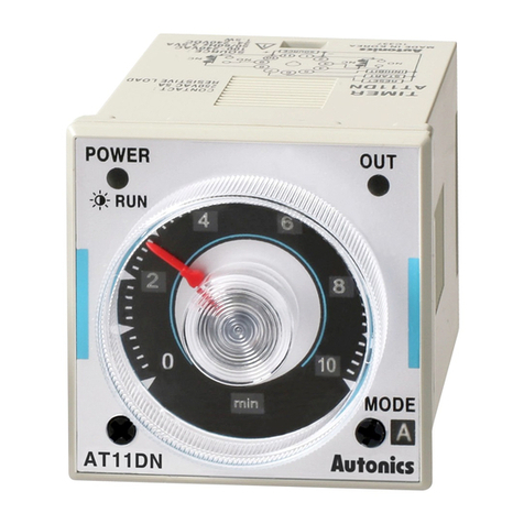
Autonics AT11DN Series instruction manual
Biogents
Biogents BG-CO2 Timer manual

KELCO
KELCO T20 Installation & programming instructions

Vaillant
Vaillant timeSWITCH 130 OPERATING AND INSTALLATION Manual
Full Gauge Controls
Full Gauge Controls ICEMATIC II quick start guide
RainPoint
RainPoint ITV205 user manual
