manuals.online logo
Brands
  1. Home
  2. •
  3. Brands
  4. •
  5. BFT
  6. •
  7. Control Unit
  8. •
  9. BFT SIRIO FR-TMA User manual

BFT SIRIO FR-TMA User manual

SIRIO
FR-TMA
D811231 02-12-02 Vers. 09
CONTROL UNIT
476
D811231_09
SIRIO FR-TMA
SIRIO FR-TMA
Thank you for buying this product, our company is sure that you will be more
than satisfied with its performance. This product is supplied with an
“InstructionManual”whichshouldbereadcarefullyasitprovidesimportant
information about safety, installation, operation and maintenance.
This product complies with recognised technical standards and safety
regulations.This product complies with the recognised technical standards
and safety regulations. We declare that this product is in conformity with the
following European Directives: 89/336/EEC and 73/23/EEC, 98/37/CEE
(and subsequent amendments). with the following Technical Standards
EN60335-1, PrEN12453 and PrEN12445.
WARNINGS
When carrying out wiring and installation work, always refer to current
standards and good technical principles.
WARNINGS
Any assistance required on automation components must be carried out by
a qualified technician (installer).
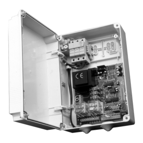
1) GENERAL OUTLINE (Fig.1)
The control panel, equipped with a microprocessor control unit, is used to
operate single-phase or three-phase controllers fitted on sliding gates and
sectional doors. It is provided with a lockable switch, open/close/stop
buttonsandawarninglightforanomalies(e.g.releaseactivated,overstroke).
A series of LEDs allows to check or detect any operating anomalies in the
control unit or on the connected devices. The control unit is supplied with
Dip-switches and Trimmers which provide configuration and calibration,
respectively. Self-diagnosis: the control unit allows a check to be carried out
on operating relays and safety devices (photocells, rubber edge etc.)
before any manoeuvre takes place.
2) GENERAL SAFETY
WARNING! An incorrect installation or improper use of the product
can cause damage to persons, animals or things.
•The “Warnings”leaflet and “Instruction booklet”supplied with this
product should be read carefully as they provide important information
about safety, installation, use and maintenance.
•Scrap packing materials (plastic, cardboard, polystyrene etc) according
to the provisions set out by current standards. Keep nylon or polystyrene
bags out of children’s reach.
•Keep the instructions together with the technical brochure for future
reference.
•This product was exclusively designed and manufactured for the use
specified in the present documentation. Any other use not specified in
this documentation could damage the product and be dangerous.
•The Company declines all responsibility for any consequences resulting
from improper use of the product, or use which is different from that
expected and specified in the present documentation.
•Do not install the product in explosive atmosphere.
•The Company declines all responsibility for any consequences resulting
from failure to observe Good Technical Practice when constructing
closing structures (door, gates etc.), as well as from any deformation
which might occur during use.
•The installation must comply with the provisions set out by the following
European Directives: 89/336/EEC, 73/23/EEC, 98/37/ECC and
subsequent amendments.
•Disconnect the electrical power supply before carrying out any work on
the installation. Also disconnect any buffer batteries, if fitted.
•Fit an omnipolar or magnetothermal switch on the mains power supply,
having a contact opening distance equal to or greater than 3mm.
•Check that a differential switch with a 0.03A threshold is fitted just
before the power supply mains.
•Check that earthing is carried out correctly: connect all metal parts for
closure (doors, gates etc.) and all system components provided with an
earth terminal.
•The Company declines all responsibility with respect to the automation
safety and correct operation when other manufacturers’components
are used.
•Only use original parts for any maintenance or repair operation.
•Do not modify the automation components, unless explicitly authorised
by the company.
•Instruct the product user about the control systems provided and the
manual opening operation in case of emergency.
•Do not allow persons or children to remain in the automation operation
area.
•Keep radio control or other control devices out of children’s reach, in
order to avoid unintentional automation activation.
•The user must avoid any attempt to carry out work or repair on the
automation system, and always request the assistance of qualified
personnel.
•Anything which is not expressly provided for in the present instructions,
is not allowed.
3) TECHNICAL SPECIFICATIONS
Power supply (*):.......................400 vac three-phase230 vac single-phase
Motor output current:...................................................................... 2A 4A
Motor output comm. current:..........................................................8A 12A
Mains - low voltage insulation:..................................... > 2MOhm 500Vdc
Mains - low voltage dielectric strength:.....................................3750Vac 1'
Maximum motor power: ........................................................750W 375W
Power supply to accessories:..............................24Vac/0,5A 24Vac/0,5A
Gate-open warning light:...................................................24V/3W 24/3W
Blinker:................................................................... 230V/40W 230V/40W
Dimensions:.................................................................................see fig.1
(*) (other voltages on request)
4) CONNECTIONS (Fig.3)
WARNINGS - For wiring and installation operations, refer to the current
standards and good technical principles.
Wires powered at different voltages must be physically separated, or
suitably insulated with at least 1 mm extra insulation. The wires must be
clamped by an extra fastener near the terminals, for example by bands.
WARNING! For connection to the mains, use a multipolar cable with
a minimum of 3x1.5mm2cross section and complying with the
previously mentioned regulations. For example, if the cable is out
side (in the open), it has to be at least equal to H07RN-F, but if it is on
the inside (or outside but placed in a plastic cable cannel) it has to
be or at least egual to H05VV-F with section 3x1.5mm2.
N.B.: Before connecting the control unit to the mains voltage, check that
the JP5 (voltage change) terminal is preset for the correct working voltage.
The board is supplied with a series of previously bridged terminals.
The jumpers refer to the following terminals: 26-29, 26-30, 26-31, 26-35.
If these terminals are not used, leave them bridged. In the additional
terminal board SSBB1, the terminals 6-7, 8-9 and 10-11 are bridged.
If these terminals are not used, leave them bridged.
PANEL
Caution: the panel power supply must be connected to the “S”breaker.
S - THREE- PHASE
R-S-T-N......................................Three-phase 400V ±10% 50Hz + Neutral.
CAUTION! (voltage change JP5/39-40).
S - SINGLE-PHASE
R-N.............................................................Single-phase230V±10% 50Hz.
CAUTION! (voltage change JP5/40-41).
CONTROL UNIT
JP1 - THREE-PHASE
1-2-3-4 Three-phase power supply+neutral 400V.
(1 Neutral, 2-3-4 phase)(Note: JP5 jumper between 39-40).
5-6-7 Three-phase motor connection.
8-9 230Vac output for blinker.
JP1 - SINGLE-PHASE
1-2 Single-phase power supply 230V.
(1 Neutral, 2 phase) (N.B.: JP5 jumper between 40-41).
5-6-7 Single-phase motor connection (5-7 motor and capacitor
operation, 6 common terminal).
8-9 230Vac output for blinker.
JP2
10-11 24Vac (3W) output for light indicating motor and/or pedestrian
access release. The light switches on when the motor is released
(manual operation) or the pedestrian access is open.
11-12 24Vac power supply to accessories and safety devices which are
not checked.
12-13 24VTx power supply only for safety device transmitters which are
checked.
14 LOOP1 input for safety device check ring (see fig.5).
15 LOOP2 input for safety device check ring (see fig.5).
16-17 Second radio channel output for two-channel receiver board
(n.o.).
18-19 Antenna input for radio receiver board (18 signal, 19 braid).
JP7
20-21-22
23-24-25 Outputs for the connection of safety devices which are to be
checked (see fig.5).
JP4
26-27 START button (n.o.).
CONTROL UNITS
CONTROL UNITS
477
D811231_09
26-28 Block button (n.c.). Additional buttons to be connected in series
with one another.
26-29 Photocell contact input (n.c.). If not used, leave on. If used while
checking, observe wiring diagram in fig.5.
26-30 Opening limit switch (n.c.). If not used, leave bridged.
26-31 Closing limit switch (n.c.). If not used, leave bridged.
26-32 Pedestrian access button (n.o.).
26-33 Open button (n.o.).
26-34 Close button (n.o.).
26-35 IR edge contact input (n.c.). If not used, leave bridged.
26-36 Individual passage micro input (pedestrian access control).
JP5
37-38 CAUTION! mains voltage across terminals.
Emergency button connection (n.c.).
Use a hold-to-run button with two n.c. contacts having a distance
of at least 8mm between the two contacts. When not used, leave
bridged.
39-40 Change of voltage to 400Vac three-phase.
40-41 Change of voltage to 230Vac single-phase.
JP6
1-2 channel radio receiver board connector.
-SSBB1 TERMINAL BOARD
1 Connected to terminal 26 of control board.
2-3-4 Auxiliary common connection.
4-5 Stop.
6-7 N.C. contact of pedestrian access micro. If not used, leave
bridged.
8-9 (N.C.) contact for SPRING 1 breakage. If not used, leave bridged.
10-11 (N.C.) contact for SPRING 2 breakage. If not used, leave bridged.
12 Connected to terminal 28 of control board.
5) CONNECTION TO SAFETY DEVICES
•In case of standard devices with 4 terminals and without self-diagnostic
function, the connection can be carried out without verification as
indicated in point 5.1.
•In case of devices featuring internal self-diagnostic function, refer to
point 5.2.
•The standard devices with 5 terminals and without self-diagnostic
functioncanbeincluded in the control and self-diagnostic cycle observing
the instructions given in point 5.3.
5.1) Safety devices WITHOUT SELF-DIAGNOSIS
Connections must be carried out as shown in fig. 4. Keep the Dip-switches
9 and 10 in the ON position (standard setting). The tripping contacts of a
group of devices of the same type, must be connected in series with one
another.
5.2) Safety devices WITH INTERNAL SELF-DIAGNOSIS
Connections must be carried out as shown in fig.4. Keep the Dip-switches
9 and 10 in the ON position (standard setting). The tripping contacts of
several devices of the same type, must be connected in series.
5.3) Safety devices WITHOUT SELF-DIAGNOSIS but with voltage-free
EX-CHANGE CONTACTS.
We conventionally make reference to a receiving device (RCS- fig.5) with
5 terminals which have the following functions: terminals 1 and 2 are for
24Vac power supply, terminal 3 is a common terminal, terminal 4 is a
normally closed contact not in use, terminal 5 is a normally open contact not
in use.
A) Fig. 5 “A”shows the wiring diagram for connecting the power supply to
those receivers and transmitters for which a self-diagnosis is required.
B) Fig. 5 “B”. Connection of one or more receivers (photocell) of the same
type up to a maximum of four (Dip 9 OFF/Dip 10 ON, photocells only,
leave jumped 35-26). For example, if there are two photocells, connect
F1 and F2, then interrupt the connection chain by connecting the
terminal 4 of F2 to LOOP1 and the terminal 5 of F2 to COM. If only one
receiver has to be connected, connection must be made as shown in
fig.5 ref.1. If the receivers to be connected are less than four, it is
necessaryto interrupt the connection chainbyperforming the connections
as shown in fig.5 ref. 2 or 3. If rubber edges instead of photocells have
to be connected, use terminal 35-BAR of the control unit.
If the devices concerned are rubber edges instead of photocells, use
terminal 35-BAR in the control unit (Dip 9 ON/Dip 10 OFF, leave jumped
29-26).
C) Connection of one photocell and one rubber edge.(Dip 9 OFF/Dip 10
OFF)
D) Connection of two photocells and one rubber edge.(Dip 9 OFF/Dip 10
OFF)
When connecting two rubber edges and one photocell, F1 and F2 in fig.5
“D”become2 rubber edges, and C1 one photocell; invert the connections
PHOT and BAR of the control unit with one another.(Dip 9 OFF/Dip 10
OFF)
E) Connection of three photocells and one rubber edge. When connecting
three rubber edges and one photocell, F1, F2 and F3 (fig.5 “E”) become
3 rubber edges and C1 one photocell; invert the connections PHOT and
BAR of the control unit with one another.(Dip 9 OFF/Dip 10 OFF)
F) Connection of three photocells and two rubber edges When connecting
three rubber edges and two photocells, F1, F2 and F3 (fig.5 “F”) become
three rubber edges, C1 and C2 two photocells; invert the connections
PHOT and BAR of the control unit with one another.(Dip 9 OFF/Dip 10
OFF)
G) Connection of four photocells and one rubber edge. When connecting
four rubber edges and one photocell, F1, F2 , F3 and F4 (fig.5 “G”)
become four rubber edges and C1 one photocell; invert the connections
PHOT and BAR of the control unit with one another.(Dip 9 OFF/Dip 10
OFF)
6) OPERATION LOGIC
6.1) Dip-switch
Dip 1 and 2 .................................................................. Photocells (FCH)
ON - Excludes photocell operation during gate opening, and immediately
reversesmovement during the closing phase when the photocellisobscured.
OFF - In the case where the photocell is obscured by an obstacle during the
closing manoeuvre, the gate is stopped; when the obstacle is removed, the
gate reopens. In the case where the photocell is obscured by an obstacle
during the opening manoeuvre, the gate is stopped; when the obstacle is
removed, the gate continues to open.
Dip 3 ................................................................... Impulse blocking (IBL)
ON - The Start / Start pedestrian impulse has no effect during the opening
phase.
OFF - The Start / Start pedestrian impulse during the opening phase causes
the gate to stop.
Dip 4 ............................................................... Automatic closing (TCA)
ON - Automatically closes the gate after a dwell time set by the TCA
trimmer.The automatic closing manoeuvre is activated after the gate has
reached the opening end-of-stroke position, after the gate opening time has
ended, or after the gate has stopped in the opening phase due to a Start
impulse.
OFF - Excludes automatic closing.
Dip 5 2 or 4 step logic (2P/4P)
ON - A Start impulse given during the closing phase reverses the direction
of movement, during the opening phase it stops the gate. (Dip-switch OFF).
OFF - A Start impulse given while the gate is moving, causes it to stop; the
following impulse reverses the running direction. (4-step logic).
N.B.: The Start impulse in the opening phase has no effect when Dip-switch
3 is ON.
Dip 6 ........................................................................ Pre-alarm (PREALL)
ON - The blinker comes on about 3 seconds before the motor starts.
OFF - The blinker comes on at the same time as the motor starts.
Dip 7 .......................................................... Open/Close command (U.P.)
Activates the signals connected to terminals 33-34.
ON - Hold-to-run operation: the manoeuvre continues as long as pressure
is maintained on the command button.
OFF - Separate automatic Open/Close operation: by means of an impulse,
it opens the gate if closed and vice versa.
Dip 8 ........................ Reduced or normal operation time range (S.TW)
ON - TW operation time ranging between 1-90 seconds (TW.PED pedes-
trian operation time from 1 to 20 seconds).
OFF - TW operation time ranging between 3÷210 seconds (TW.PED
pedestrian operation time from 5 to 60 seconds).
Dip 9 ........................................................ Unchecked photocells (FNV)
Activates the photocell control logic.
ON - The photocells are excluded from the safety check cycle which is
carried out before each manoeuvre; however their logic state is analysed
(for connection, refer to the typical method of connecting photocells with
continuously active beams). This is used to connect photocells which have
not been checked or have internal self-diagnosing systems, and always
provide a voltage-free output contact.
OFF - The photocells are included in the Ok safety check cycle which is
carried out before each manoeuvre. For connection, refer to the enclosed
diagrams.
Dip 10 ................................................................ Unchecked edge (BAR)
Activates the rubber edge device control logic.
ON - The edge devices are excluded from the safety check cycle which is
carried out before each manoeuvre; however their logic state is analysed
(for connection, refer to the typical method of connecting infrared edges
SIRIO FR-TMA
SIRIO FR-TMA
CONTROL UNITS
CONTROL UNITS
478
SIRIO FR-TMA
SIRIO FR-TMA
CONTROL UNITS
CONTROL UNITS
with continuously active beams). This is used to connect IR edges which
have not been checked or have internal self-diagnosing system, and
always provide a voltage-free output contact.
OFF - The IR edge devices are included in the Ok safety check cycle which
is carried out before each manoeuvre. For connection, refer to the enclosed
diagrams.
6.2) Trimmer-set functions
TW.PED Sets the partial operation time of a sliding gate which is being used
for both vehicles and pedestrians.
TW Sets the operation time during both the opening and closing phases
(adjustable from 3 to 210 seconds).
TCA Sets the dwell time, after which the gate closes automatically (from 1
to 120 seconds).
6.3) LED functions
The SIRIOTMA control unit is provided with leds which are useful in
identifying any anomalies in the system.
(DL1) Stays on when supplied with mains power and with F1 fuse intact.
(DL2) Comes on when the motor is activated during closing.
(DL3) Comes on when the motor is activated during opening.
(DL4) Comes on following the Start command or the activation of the first
radio-receiver channel.
(DL5) Goes off when the block command is activated.
(DL6) Goes off when photocells are not aligned, i.e. when obstacles are
present. When Dip-switch 9 is OFF, the photocells and related leds are only
activated during manoeuvring.
(DL7) Goes off when the gate is in the completely open position, if provided
with end-of-stroke device.
(DL8) Goes off when the gate is in the completely closed position, if
provided with end-of-stroke device.
(DL9) Comes on at the Start command for pedestrian gate.
(DL10) Comes on with manual opening command.
(DL11) Comes on with manual closing command.
(DL12) Goes off when the pneumatic edge is activated. When Dip-switch
10 is OFF, the edge and its related LED are only activated during
manoeuvring.
(DL13) Comes on when the safety ring is closed.
(DL14) Comes on when the safety micro has stepped in.
7) MAINTENANCE AND DEMOLITION
The maintenance of the system should only be carried out by qualified
personnel regularly. The materials making up the set and its packing must
be disposed of according to the regulations in force. Batteries must be
properly disposed of.
The descriptions and illustrations contained in this manual are not
binding. The Company reserves the right to make any alterations
deemed appropriate for the technical, manufacturing and commercial
improvement of the product, while leaving the essential product
features unchanged, at any time and without undertaking to update
the present publication.
D811231_09
479
D811231_09
Fig. 1
Fig. 2
12
NL
3456789
N R S T M1 M2 M3 BLINK
10 11 12 13 14 15 16 17 18 19
SCA 24VAC TX L1 L2 IICAN ANT SHLD
20 21 22 23 24 25
NAR NCB CFB NAA NCA CFA
26
U8
K10
R5
JP6
JP1 JP2
JP7
JP5 RV1
F1
T1
U3
U2
U1
0.2AT
RICEV
DL2
DL14
DL3 DL4 DL5 DL6 DL7 DL8 DL9 DL10 DL11 DL12 DL13
DL2
U6
U5 U10
D20 D19 D18 D14 D15 D26 D13 D16 D17
U7
27 28 29 30 31 32 33 34 35 36
COM STARTSTOP PHOT SWO SWC PED
OPEN CLOSE
BAR
MICRO
41 40 39 38 37
230V S 400V Safety
SIRIOTMA
SSBB1
DIP function
1 FCH
2 FCH
3 IBL
4 TCA
5 2P/4P
6 PREALL
7 U.P.
8 S.TW
9 FNV
10 BAR
12
TWPED -+
+
- TCA + - TW
R31
C37 C8
C11
U4
2AT F2
R1
C1
C2
C3
C7
C4 IC1
Y1
K8
K9
F3
F2A
R105
K7
K4
K3
K2
K1
R8
R6
R7
R104
R32 R33
+
+
+
+
345678910
ON
123456789101112
SSBB1
SIRIOTMA
Cavallotto di messa a terra
U-link for earth connection
Crampillon de mise àla terre
Erdanschlussklemmen
Perno de U de toma de tierra
Cabo descarnado de ligação àterra
Disponibilitàdi raccordi tubo - cassetta:
CRTR (raccordo con tubo rigido).
CRTL (raccordo con guaina flessibile).
Available couplings connecting the pipes to the box:
CRTR (coupling with rigid pipe).
CRTL (coupling with flexible sheath).
Disponibilitéde raccords tube - boîte:
CRTR (raccord avec tube rigide).
CRTL (raccord avec tuyau souple).
Erhältliche Rohrverschraubungen für Steuerungsgehäuse:
CRTR (Verbindungsstück für starres Rohr).
CRTL (Verbindungsstück für flexibles Rohr).
Disponibilidad de uniones tubo - caja:
CRTR (unión con tubo rígido).
CRTL (unión con vaina flexible).
Disponibilidade de conectores tubo - caixa:
CRTR (conector com tubo rígido).
CRTL (conector com bainha flexível).
Sezionatore
Knife switch
Disjoncteur
Trennschalter
Interruptor
Seccionador
Gruppo fusibili
Fuse set
Groupe fusibles
Sicherungsgruppe
Grupo fusibles
Grupo fusíveis
SIRIO FR-TMA
SIRIO FR-TMA
CONTROL UNITS
CONTROL UNITS
480
D811231_09
Fig. 3 Fig. 4
Fig. 5
SIRIOTMA
Rx FL Rx RI
Tx FL Tx RI
35
BAR
Dip 9 ON
29
PHOT
26
COM
11
12
13
24VAC
1 2 3 4 5
1 2 1 2
Dip 10 ON
1 2 3 4 5
JP1 JP2
JP7
fig.5
123 4 5 6 7 8 910 1911 12 13 14 15 16 17 18 20 21 22 23 24 25
JP4 JP5
26 36
27 28 29 30 31 32 33 34 35 37 38 39 40 41
N
7
M
230V
40W
24V
3W ANT.
CH2
24V Tx
LOOP1
LOOP2
24Vac
NO
NC
NC
NC
NC
NO
NO
NO
COM
START
STOP
PED
APRE
CHIUDE
PHOT
BAR
MICRO
SAFETY
SWO
SWC
400V
S
230V
R
1
(L)
S
3
T
5
8
N
2
U
4
V
S
6
W
123456789
10 11 12
SSBB1
11112
2 3 4 5 6 7 8 9 10
COM M1 M2
STOP
SAFETY
NC NO
MPU
C
P1
SIRIO TMA
SIRIO TMA
F4 F3
4-14 LOOP1 / 5-26 COM
F2 F1
1 2 3 4 5 1 2 3 4 5 1 2 3 4 5 1 2 3 4 5
22
14-LOOP1
26-COM
25
21
20
24
23
26-COM
29-PHOT
35-BAR
4-14 LOOP1 / 5-26 COM 3-26 COM / 4-14 LOOP1
3 2 1
SIRIO TMA
C1 F1
1 2 3 4 5 1 2 3 4 5
24
35-BAR
15-LOOP2
26-COM
29-PHOT
SIRIO TMA
C3 F2
1 2 3 4 5 1 2 3 4 5
35-BAR
F1
1 2 3 4 5
15-LOOP2
24
23
26-COM
29-PHOT
RX
24Vac
A
24VTx
TX
5
4
2
1
3
2
1
13
12
12
11
SIRIO TMA
F3 F2
1 2 3 4 5 1 2 3 4 5
26-COM
F1
1 2 3 4 5
25
C1
1 2 3 4 5
35-BAR
15-LOOP2
24
26-COM
26-COM
29-PHOT
SIRIO TMA
F3 F2
1 2 3 4 5 1 2 3 4 5
26-COM
F1
1 2 3 4 5
25
C2
1 2 3 4 5
26-COM
22
24
23
26-COM
29-PHOT
C1
1 2 3 4 5
20
21
15-LOOP2
SIRIO TMA
F3 F2
1 2 3 4 5 1 2 3 4 5
20
F1
1 2 3 4 5
25
21
F4
1 2 3 4 5
26-COM
22
24
23
26-COM
29-PHOT
C1
1 2 3 4 5
35-BAR
15-LOOP2
B C
D E
F
G
Legenda
P1: Pulsante arresto a bordo quadro
MPU: Micro controllo porta passo uomo
M1-M2: Micro controllo rottura molle
Key
P1: Stop button on panel
MPU: Check micro for pedestrian access
M1-M2: Check micro for spring failure
Légende
P1: Bouton d’arrêt sur le tableau
MPU: Micro de contrôle de la porte pas d’homme
M1-M2: Micro de contrôle de la rupture des ressorts
Zeichenerklärung
P1: Stopknopf auf der Tafel
MPU: Mikroschalter zur Kontrolle der Durchgangstür
M1-M2: Mikroschalter zur Feststellung von Federbrüchen
Leyenda
P1: Botón de parada colocado en el cuadro
MPU: Microinterruptor de control puerta paso peatonal
M1-M2: Microinterruptor de control rotura muelles
Legenda
P1: Pulsante arresto a bordo quadro
MPU: Micro controllo porta passo uomo
M1-M2: Micro controllo rottura molle
Legenda
RX: ricevente fotocellule o coste infrarossi.
TX: trasmittente fotocellule o coste infrarossi.
F1 - F2 - F3 - F4: dispositivi riceventi fotocellule.
C1 - C2 - C3 - C4: dispositivi riceventi coste sensibili.
Key
RX: photocell receiver or infrared rubber edges.
TX: photocell transmitter or infrared rubber edges.
F1 - F2 - F3 - F4: photocell receiving devices.
C1 - C2 - C3 - C4: rubber edge receiving devices.
Légende
RX: récepteur cellules photoélectriques ou barres palpeuses àinfrarouges.
TX: émetteur cellules photoélectriques ou barres palpeuses àinfrarouges.
F1 - F2 - F3 - F4: dispositifs récepteurs cellules photoélectriques.
C1 - C2 - C3 - C4: dispositifs récepteurs barres palpeuses.
Zeichenerklärung
RX: Empfangsteil der Photozellen oder Infrarotleisten.
TX: Sendeeinheit der Phototellen oder Infrarotleisten.
F1 - F2 - F3 - F4: Empfangsvorrichtungen der Photozellen.
C1 - C2 - C3 - C4: Empfangsvorrichtungen der Sicherheitsleisten.
Leyenda
RX: receptor fotocélulas o barras de infrarrojos.
TX: receptor fotocélulas o barras de infrarrojos.
F1 - F2 - F3 - F4: dispositivos receptores fotocélulas.
C1 - C2 - C3 - C4: dispositivos receptores barras sensibles.
Legenda
RX: ricevente fotocellule o coste infrarossi.
TX: trasmittente fotocellule o coste infrarossi
F1 - F2 - F3 - F4: dispositivi riceventi fotocellule.
C1 - C2 - C3 - C4: dispositivi riceventi coste sensibili.
SIRIO FR-TMA
SIRIO FR-TMA
CONTROL UNITS
CONTROL UNITS

Other manuals for SIRIO FR-TMA

2

Other BFT Control Unit manuals

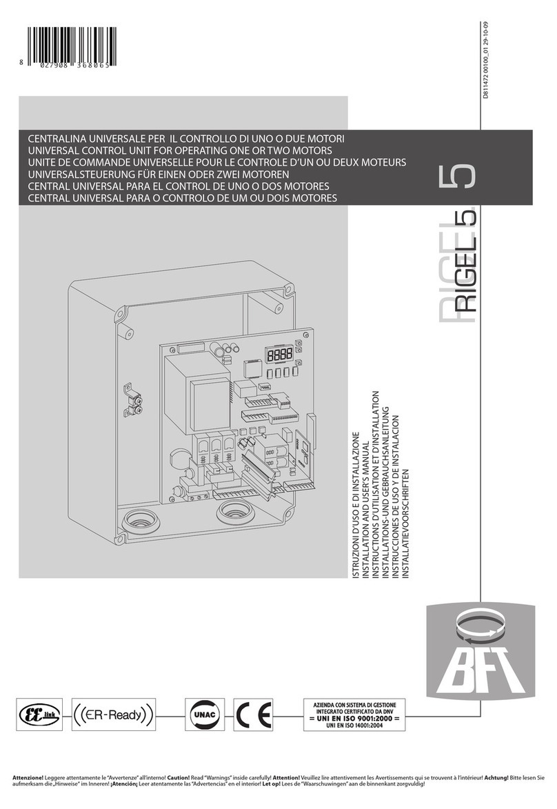
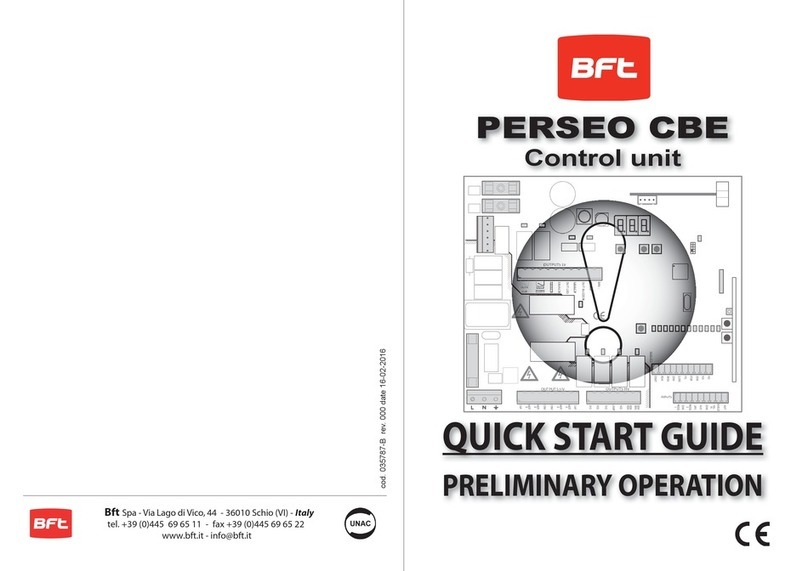
BFT PERSEO CBE User manual

BFT

BFT PERSEO CBE User manual

BFT RIGEL 5 User manual

BFT

BFT RIGEL 5 User manual

BFT RIGEL 5 User manual

BFT

BFT RIGEL 5 User manual

BFT Compass-485 User manual

BFT

BFT Compass-485 User manual

BFT MICRO N1 User manual

BFT

BFT MICRO N1 User manual

BFT CPEL User manual

BFT

BFT CPEL User manual

BFT SIRIO FR-TMA User manual

BFT

BFT SIRIO FR-TMA User manual

BFT BEBA Z-WAVE User manual

BFT

BFT BEBA Z-WAVE User manual

BFT RIGEL 5 User manual

BFT

BFT RIGEL 5 User manual

BFT SD User manual

BFT

BFT SD User manual

BFT ELBA User manual

BFT

BFT ELBA User manual

BFT RIGEL 5 User manual

BFT

BFT RIGEL 5 User manual

BFT BOX User manual

BFT

BFT BOX User manual

BFT PERSEO-CBE User manual

BFT

BFT PERSEO-CBE User manual

BFT LIBRA C MA Installation and operating instructions

BFT

BFT LIBRA C MA Installation and operating instructions

BFT SUPER MA User manual

BFT

BFT SUPER MA User manual

BFT MICHELANGELO 60 User manual

BFT

BFT MICHELANGELO 60 User manual

BFT B EBA RS 485 LINK User manual

BFT

BFT B EBA RS 485 LINK User manual

BFT MOOVI BT 30 User manual

BFT

BFT MOOVI BT 30 User manual

BFT ALTAIR User manual

BFT

BFT ALTAIR User manual

BFT MIZAR UL User manual

BFT

BFT MIZAR UL User manual

BFT ME BT User manual

BFT

BFT ME BT User manual

BFT POLLUCE 2M User manual

BFT

BFT POLLUCE 2M User manual

BFT SIRIO FR-TMA User manual

BFT

BFT SIRIO FR-TMA User manual

Popular Control Unit manuals by other brands

AVCO 1100 Series Installation, operation & maintenance manual

AVCO

AVCO 1100 Series Installation, operation & maintenance manual

Skov BlueControl Insect Technical user guide

Skov

Skov BlueControl Insect Technical user guide

GEA ECOVENT TEFASEP-Gold ECO E Assembling Instruction

GEA

GEA ECOVENT TEFASEP-Gold ECO E Assembling Instruction

SVS SHR-7 manual

SVS

SVS SHR-7 manual

Bosch MS 6 manual

Bosch

Bosch MS 6 manual

Leviton 47616-DSB installation instructions

Leviton

Leviton 47616-DSB installation instructions

Emco A1100EVR GUARDIAN installation instructions

Emco

Emco A1100EVR GUARDIAN installation instructions

GatesAir Intraplex DS-64NC Installation and operation manual

GatesAir

GatesAir Intraplex DS-64NC Installation and operation manual

Freescale Semiconductor TWR-VF65GS10 user manual

Freescale Semiconductor

Freescale Semiconductor TWR-VF65GS10 user manual

SEA GATE 1 DG R2BF manual

SEA

SEA GATE 1 DG R2BF manual

Emerson PACSystems RX3i quick start guide

Emerson

Emerson PACSystems RX3i quick start guide

VersaLogic VersaFlap H.25 Manual instructions

VersaLogic

VersaLogic VersaFlap H.25 Manual instructions

Rockwell Automation Allen-Bradley FLEX Ex 1797-IRT8 user manual

Rockwell Automation

Rockwell Automation Allen-Bradley FLEX Ex 1797-IRT8 user manual

Leviton SureSlide 6637 installation instructions

Leviton

Leviton SureSlide 6637 installation instructions

Festo CPX-E-PN manual

Festo

Festo CPX-E-PN manual

Fostoria VHC-66 installation instructions

Fostoria

Fostoria VHC-66 installation instructions

Knorr-Bremse BENDIX TIM G2 user manual

Knorr-Bremse

Knorr-Bremse BENDIX TIM G2 user manual

Beninca CP.B24-SW quick start guide

Beninca

Beninca CP.B24-SW quick start guide

manuals.online logo
manuals.online logoBrands
  • About & Mission
  • Contact us
  • Privacy Policy
  • Terms and Conditions

Copyright 2025 Manuals.Online. All Rights Reserved.