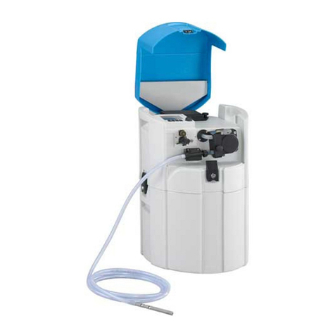
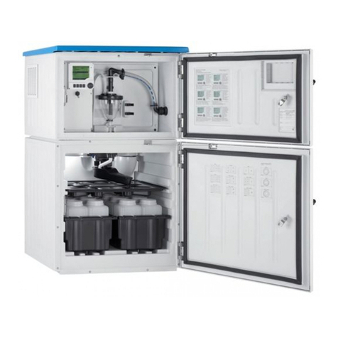
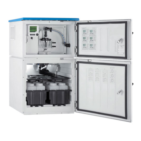
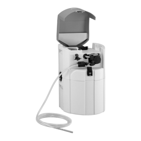
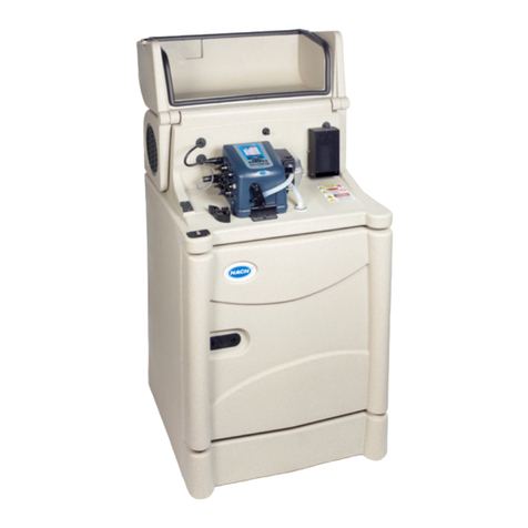
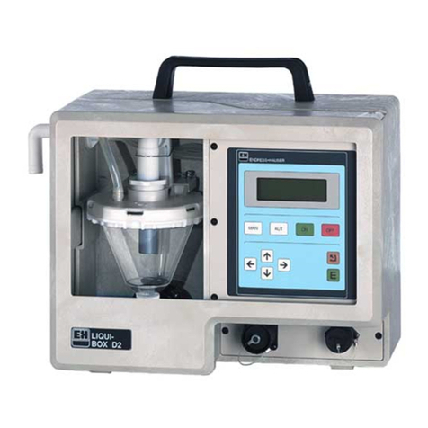
Endress+Hauser asp-station a 2 User manual

Water sampler
asp-station a 2
Installation and operating instructions
BA 020R/09/en/04.97
Part No. 50051343
Nothing beats know-how
Endress Hauser


Complete delivery ●Check: That the delivery note and delivery contents correspond!
Check the package and contents for external damage.
Should there be any visible damage you should immediately inform
both the transport agency as well as your supplier. If this is not done
any later claims cannot be handled under the guarantee.
Transport insurance
Please take note of the following characters:
Hint: Hints for better installation.
Attention: Ignoring this note can lead to damage of the
device or faulty operation.
Danger: Ignoring this warning can lead to personal injury.
Should the "asp-station a 2" be in storage for more than 6 months
please take note of the storage details in chapter
"Maintenance, general".
Please note

Dimensional drawing,
complete unit
Dimensional drawing, complete unit with all options
(above).
A = Roof (option)
B = Suction hose (accessories)
C = Sampler
asp - station a 2
D = Power cable
E = Base (option)
Note: All dimensions shown are for the "standard housing".
For "wide housing" dimensions see technical data.
Sampler
asp-station a
(left):
1 = Controller
liqui-box a
2
2 = Distribution tray (tap and tray)
3 = Bottle tray with bottles and lids
4 = Terminal box (behind cover plate)
5 = Refrigeration unit (inside lower part of housing)
Extra: Flow through armature if needed is fitted
in the lower right part of the sampler.
1
2
3
4
5
Wetzer Meßtechnik Printed in W. Germany (INT)
Modifications reserved
asp - station a 2

"liqui-box a 2" construction A Housing
BDisplay and operating components (controller)
C Power supply socket (connected to terminal box in lower part)
DElbow connector (for suction hose)
ESignal in and output socket (connected to terminal box)
FHose clamp
HSample release hose (for connection to sample distribution
system
K Wet compartment
L Dosing system
MLegend plate (unit number, supply voltage, power consumption
of functional module)
Operating elements and
display 1 MAN-push button: Immediate sample start
2 AUT-push button: Automatic sample sequence start
3 ON-push button: Switches unit on
4 OFF-push button: Switches unit off
5⇐push button: Operation mode selection
6 - push button: Reduce target value
7 + push button: Increase target value
8INFO- display field: Information (pump running times etc.)
9TEMP- display field: Cabinet temperature display
10 IMP- display field: Quantity proportional sampling
11 TIME- display field: Time proportional sampling
12 PRESET Sample and temperature target values
13 SAMPLE Sample selection (heading)
14 Sampling display fields (total)
15 STATUS Sample and temperature actual values
16 ⇐push button Operation mode selection
17 + push button Increase target value
18 - push button Reduce target value
19 INFO- display field: Information (samples not taken)
20 END- display field: Sample sequence end or continuous
operation
21 SUM- display field: Number of samples per container
22 TIME-display field: Fill time per container
23 STATUS Actual value for sample sequence end
24 PRESET Target value for sample sequence end
25 DISTRIBUTION Sample distribution (heading)
26 Sample sequence end and distribution display fields (total)
Component description

B
F
A
E
HM
D
LC
K
2
25
24
10 9 8
16
18
17
76543
23
22 21 20 19 11
12
26
13
1
15
14
Operating components and display
Functional module construction

Page
asp-station a 2
- Construction, - dimensional drawing
Please note:
- If the delivery is complete
- Transport insurance
Construction of functional module
- Operating elements and display
General notes 2
- Safety 2
Mechanical installation 3
- General 3
- Installation 3
- Hose connection/installation 3
- Recommendations and accessories 4
- Foundation recommendation 4
Electrical installation 6
- Power supply 6
- Terminal box 6
- In / outputs 7
- Outputs 7
- Inputs 7
- Terminal connections 7
- Connection examples 8
- Input 8
- Output 8
- What happens on power up ? 8
- Power failures 8
- Switching on and off
(ON/OFF push buttons) 8
Operating components and
setting up principle 9
Sampling principle 10
Setting up sample volume 11
- Setting up steps (1 to 8) 11
Page
Methods of sampling 14
- Manual sampling 14
- Automatic sampling 14
- Time proportional 14
- Quantity proportional 15
- Event controlled sampling 15
- Setting up sample sequence end 16
- With sample distribution 16
- With composite container 16
- Setting up bottle change (distribution) 17
- Time base 17
- Number of samples taken 17
Additional functions 18
- Countdown
- Sample cycle interrupt / restart 18
- Alterations during operation 18
- Refrigeration and heating 18
Additional information 19
- Information that can be called up 19
- Pump running times and faults 19
- Number of not taken samples 19
Example 20
Sample distribution conversion 21
- Changing number of
containers / bottles 21
Maintenance 22
- General 22
- Repairs 22
Problems and solutions 23
- Fault messages 23
- Spare parts 25
Technical data 26
Contents
1

Safety This unit is constructed and tested according to EN 61010-1 /
VDE 0411 Part 1 and left our works in perfect and safe condition. In
order to maintain this condition and operate safely the user must take
note of the following safety information and warnings contained in
these instructions.
First check that the power supply to be used corresponds with that on
the unit legend plate.
This unit is supplied with a loose power cable including plug and
socket arrangement and is therefore classified to protection class I.
The power supply plug must only be connected to a socket with an
earth protection connection. This protection must be continued when
using extension leads. Any breakage of the earth conductor within or
outside the unit or loosening the earth connections can make the unit
potentially dangerous. Intentional disconnection or an open circuit of
this earth connection is not permissible.
There are no components in the unit that can be repaired by the user.
All repairs must be made by trained service personnel.
Removing covers or components, except where this can be done by
hand, must only be carried out by skilled personnel.
If it is assumed that the unit cannot be safely operated it must be
immediately taken out of operation and secured against unintentional
use.
It can be assumed that the unit cannot be safely operated,
- if the unit is visibly damaged
- if the unit no longer operates
- if the unit has been in storage under adverse conditions for a longer
period of time
- after long transport under adverse conditions.
The manufacturer does not accept liability for any damage that has
been made due to the unit not having been used in accordance with
these safety instructions.
General notes
2

GeneralRemove the external protection film as soon as possible as this can
stick due to sun rays.
The water sampler must be installed so that it stands higher than the
sampling point. It can be installed outside and mounted on a concrete
foundation or solid level ground. The unit can be levelled by using the
four levelling screws fitted in the bottom of the sampler. All
components are mounted in a lockable, thermostatically controlled
stainless steel cabinet.
The cabinet must be installed in an area where an additional heating
effect from external sources (eg. radiators, etc.) is avoided. In order to
ventilate the built in refrigeration system the sampler, when mounting
next to a wall, must be fitted with the 50mm long spacers supplied in
the accessory pack.
Do not install the sampler close to large magnetic fields (eg. motors,
transformers, large contactors, etc). Do not install the sampler in areas
where it can be subject to high mechanical vibration. Avoid shocks
when transporting the sampler.
The suction hose must be installed so that it always rises from the
sampling point to the hose connection on the sampler !
Syphons must be avoided between the sampling point and
sampler !
Right
The sampler must not be connected to a pressurised system !
For sample lift less than 2 m we recommend using a 15 mm suction
hose. Both 13 mm and 15 mm connections are delivered.
The minimum conductivity of the sample liquid must not be less than
30 microsiemens !
●The 13 mm internal ∅hose must be of a spirally reinforced type.
●The hose can be connected to the connector on the top left hand
side of the cabinet.
●Maximum height difference: 6m from sampling point to sampler.
●Maximum hose length: 30m
Wrong
Mechanical installation
3

Recommendations and
accessories The suction hose must always be submerged in liquid at the sampling
point. Suitable measures for this are:
Weight the end of the hose using a short length of V2A tubing or fixing
the hose to the channel (tank) wall using a hose saddle or the
submersion armature (can be ordered as an accessory).
Submersion armature: PVC. is pivoted to move in all directions. Order No. 50038168
A suction filter can be used in
applications where large solids
particles are not required in the
sample.
A= Filter
B= Connector
C= Jubilee clip
Filter order No. 50038327
Recommendation:
Never submerge the hose against
the flow direction !
If possible always sample with the flow.
Sampler with flow through
armature Flow rate min.200l/h max.1500l/h
Vacuum sampling from A
Inlet B3/4"
Outlet C11/4"
Attention: It must be guaranteed
that liquid flow at the outlet C is
free to atmosphere. Should the
system come under pressure the
water head at A will rise and can
lead to flooding the sampler.
We accept no liability for damage caused by ignoring this information !
Mechanical installation
4

Foundation recommendation
(For standard units)
A = Fixing dimensions (There are four 10 mm dia holes in the base of the cabinet)
B = Defrost water drain.
C = Possible cable entries.
Mechanical installation
5

The sampler is delivered with a 3core mains cable (length approx.
1.4m) connected to a 2 pin plug with earth contact.
This cable is fed through the sampler left side panel and is already
connected to the mains terminals in the terminal box.
Terminal box Open the cabinet door.
The terminal box is situated behind the hinged blanking plate (2) at the
base of the sampler.
Remove the mains plug from the power supply (the system must be
without power).
Push both snap locks (1) inwards and hinge the blanking plate (2)
downwards. The terminal box (3) can now be seen.
Undo screws (4) and remove the terminal box lid. (There is a terminal
connection diagram stuck to the inside of the lid).
The terminal box contains all in/output terminals, internally connected
cables to the functional module, alarm and sample sequence end relay
outputs (for retransmission), heating and cooling relays (internal) as
well as the mains fuse SI1 (6,3AT).
For skilled personnel only:
Cable connections through PG glands. Only use terminal strips
KL6, KL7, KL9.
Connection sticker inside
terminal box lid
Internally connected
11
24
3
4
Electrical installation
6

Terminal connectionsKL 9/1 Auxiliary voltage 0 Volt
KL 9/2 Auxiliary voltage +8...+18,5 Volt (max. 200 mA)
KL 9/3 Impulse input (pos. quantity impulses)
KL 9/4 Stop input (logic high stops sampling sequence)
Sample sequence end output, potential free changeover contact:
KL 6/1 Normally closed
KL 6/2 Normally open
KL 6/3 Common (Power failure, sample sequence end: 1 and 3
closed)
Alarm output, potential free changeover contact:
KL 7/1 Normally closed
KL 7/2 Normally open
KL 7/3 Common (Power failure, Alarm: 1 and 3 closed >30 seconds.
In / outputs
OutputsThe controller has 2 outputs for alarm and sample sequence end.
These outputs are individual potential free changeover contacts. When
active (in alarm) or during a power failure terminal 1 is connected to
terminal 3 (valid for KL6 and KL7)
Limit data: Umax.: 300V-/250V~I
max.: 8A Pmax.: 50 / 220W
Sample sequence endOutput (KL6) signals sample sequence end (changeover from 2-3 to
1-3):
*When the preset sample sequence has finished.
*On power failure
*The contact returns to 2-3 when a new automatic sampling sequence
programme is started.
AlarmOutput (KL7) signals Alarm (changeover from 2-3 to 1-3 as a ≥30sec
impulse contact.):
*When a fault has occurred during a sample cycle.
The respective error message appears in the display.
For fault descriptions see chapter "Problems and solutions"
Inputs
Flow impulse inputs1 Impulse input (KL9, terminal 3 via opto coupler) max.25Hz
(+7 to +27 Volt).
For connecting an external quantity measuring system
External stop1 Stop input (KL9, terminal 4 via optocoupler).
A voltage between +7 to +27 Volt on the input stops all sampler
functions (eg. for connection to an external timer)
0 Volt (or open circuit) to +3 Volt initiates normal operation (the status
display restarts at zero, the next sample is taken once the target value
is reached). For further information to this function see chapter
"Interrupt/restart sample cycle".
Electrical installation
7

Connection examples Alternatives: In example "Impulse input for flow input"
a: Using external aux. voltage b: Using internal aux. voltage
Output The outputs (KL6/KL7) are individual (potential free) changeover
contacts and can be directly connected to either DC or AC sources.
(KL9 terminals 5/6 are normally not to be connected = Transistor output max.20mA DC)
What happens on power up ? a) The display shows “INIT”, unit does a self test (start up). Display
shows “OFF”. Switch sampler on by operating the “ON” push
button. The unit continues to operate using the data from before the
power failure. If required reset data by operating and restart the
sampler by operating the "AUT" push button.
Power failures b) Short term power failures during operation:
The sampler continues to operate as normal after power return. The
auxiliary output power supply is not available during power failure
(the inputs continue to be scanned). Samples are not taken, but the
internal electronics continue to operate and the lost samples are
added into the "INFO" counters. See chapter "Additional
information". Missed distribution switchings are done on power
return.
c) Long term power failures (internal buffer accumulator discharge):
The error message "E09PrES" is displayed and the distribution arm
goes to its zero position (between last and first bottle). Operate push
button OFF, followed by push button ON, set up operation data
again. The system restarts at the first bottle when "AUT" is operated.
Note: The internal buffer accumulator is automatically recharged on return of power.
On/off switching using the
ON and OFF push buttons a) Switch off (operate OFF): This switches the operating cycle off. The
system should not be switched off during a sample cycle, always
wait until the unit has completed the cycle. Display shows "OFF",
the sampler is switched off (mains power is still available).
The refrigeration system continues to operate as normal.
b) Switch on (operate ON): Display shows "END". The sampler can be
restarted (using new data if required). The sampler starts operating
using the first bottle.
+
b
a
K
L
9
K
L
9
Electrical installation
8

Operating elementsSee drawings at the front of these instructions ("Operating
components and display")
Operating principle
"ON" push buttonPush button “ON” (3) activates the
"liqui-box a 2"
controller
- The display shows the last operation
sequence values.
"OFF" push buttonPush button "OFF" (4) switches the
"liqui-box a 2"
off.
- The display (14) shows "OFF"
“ ⇐” push buttonPush buttons “ ⇐”(5and 16) change the mode of operation
- Display arrowhead ▼changes to the next field.
- Display arrowhead ▼flashes for a few seconds,
then the new settings are accepted (always wait
for the arrowhead to stop flashing).
"+" and "-" push buttonsPush buttons “+” (7and 17) and “−” (6and 8) change the target
value (12 and 24)
- Simultaneous operation of "+" and "−"changes
the display to auf 0001 (Reset).
- If the target value is changed the arrowhead ▼flashes.
- Once the arrowhead ▼is stable the new values are
accepted and stored.
"AUT" push buttonPush button “AUT” (2) starts an automatic sampling sequence.
Count down"Count down" to sample sequence start:
If the "AUT" (2) push button is operated for more than approx 5
seconds a preset counter appears in the display. Once this counter
has be set the arrowhead ▼flashes.
Once the arrowhead is stable the counter counts down in a minute
cycle. The sampler is now blocked. Once 0000 is reached the sampler
starts automatic sample operation using the preset sampling data.
"MAN" push buttonPush button "MAN" (1) initiates an immediate sample cycle.
Operating elements and operating principle
9

Sampling principle
Vacuum principle
-
+
2A fresh sample is then
sucked into the dosing
chamber until the
conductivity level switch is
activated (sensors in the
dosing chamber flange)
4The hose clamp is released
and the sample flows into the
composite container or
bottles if operating using
sample distribution.
=
=VP
D
1The dosing system is
pneumatically sealed at the
beginning of each sample
cycle. The diaphragm pump
then blows the suction hose
free of obstructions via the
dosing chamber
3The sample is now dosed to
the preset volume (VP). This
is dependent on the dosing
tube position (D). Excess
liquid flows back to the
sampling point due to a
syphonic effect.
Sampling principle
10

Varying sample volumeFollow the next steps.
1. Open controller door
2. Switch unit offOperate the - OFF- (4) push button at the "liqui-box a 2".
Dosing system:
➀= Elbow
➁= Dosing tube
➂= Dosing chamber
➃= Piping clamp 3. Remove air hose
1
2
3
4
Sampler operation
11

4. Remove dosing system Lift clamp from pipe elbow.
Pull dosing system forwards
and remove from controller.
5. Remove flange Release the bayonet fitting by
turning the lower part of the
flange as shown. Remove the
flange from the dosing chamber.
6. Set sample volume Set the dosing tube to the
required sample volume by
pushing it in or out. Take note
of the engraved quantities on
the tube. (The further the tube
is pulled out of its retainer the
smaller the sample volume)
(Only move the dosing tube.
NEVER loosen the nut and
NEVER move the upper elbow.)
Use the following calculation in order to avoid overfilling the sample
containers:
Preset sample volume x number of samples = Container volume
300
350
400
450
500
Sampler operation
12

7. Dosing system➀ = Nipple
➁ = Suction pipe elbow
➂ = Hose clamp
➃ = Contacts
➄ = Spring contacts
➅= Fixing clamp
➆ = Silicon hose
●Push silicon hose ➆into the hose clamp ➂.
●Push suction pipe elbow ➁onto the nipple ➀. (Make sure that the
spring contacts and flange contacts are made).
●Push fixing bracket ➅downwards.
"The contacts ➃and contact springs ➄must be made
(otherwise faults can occur).
We cannot be held responsible for damage caused by not complying
with these instructions !
8. Replace air hose
Sampler operation
13

Methods of sampling
Manual sampling Operate push button MAN.
Starts an immediate sample cycle
This can be done as often as required and can be repeated at any
time.
Automatic sampling One of three possible sampling methods can be selected
a) Time proportional sampling
b) Quantity proportional sampling
c) Event controlled sampling
a) Time proportional sampling Q = Sample volume
t = Time intervals
Principle: Samples of identical volume are taken in preset identical time cycles.
Time spans of 0001 min. to 9999 min. are possibleI
Operate push button ⇐as often as required to bring the flashing
arrowhead ▼over the display field marked as TIME .
Set the time span between each sample cycle in minutes using push
buttons - or +.
Continuous operation of push buttons
-
or
+
causes the numbers in the
display to scroll at a faster speed.
The controller has accepted and stored the new values once the
arrowhead ▼over the display field
TIME
has stopped flashing.
Do not select a sample time span smaller than the time it takes to
complete a sample cycle.
Continue with "Setting up bottle change" and "Setting up sequence end".
0001 min
0000 min
Sample cycles
1234
Sampler operation
14
Table of contents
Other Endress+Hauser Sampler manuals

Endress+Hauser
Endress+Hauser Liquistation CSF28 Technical specifications

Endress+Hauser
Endress+Hauser Liquiport CSP44 Technical specifications

Endress+Hauser
Endress+Hauser ASP Inline User manual

Endress+Hauser
Endress+Hauser Liquistation CSF33 User manual

Endress+Hauser
Endress+Hauser ASP Station 2000 peristaltic User manual

Endress+Hauser
Endress+Hauser Liquistation CSF48 User manual

Endress+Hauser
Endress+Hauser Liquiport 2010 CSP44 User manual

Endress+Hauser
Endress+Hauser Liquistation CSF48 Technical specifications

Endress+Hauser
Endress+Hauser Liquistation CSF34 Technical specifications

Endress+Hauser
Endress+Hauser Liquistation CSF28 User manual