Endress+Hauser Liquistation CSF48 Technical specifications

BA443C/07/EN/13.10
71122369
Valid as of:
Software version 01.01.00
Operating Instructions/Brief Operating Instructions
Liquistation CSF48
Automatic sampler for liquid media
Commissioning

Overview of documentation
Operating Instructions
The Operating Instructions are split into several parts:
Commissioning (BA443C)
• All steps that have to be carried out once only during the initial commissioning
• Description of menus:
– Basic settings
– Display/Operation
• Technical data
Operation & settings (BA464C)
• Configuration of inputs and optional outputs
– Analog inputs
– Binary inputs/outputs
– Current outputs
– Alarm relays
–Relays
• Sampling programs
• Logbooks
• Individual settings for the inputs:
– Sensor-specific settings
– Calibration settings
– Sensor-related diagnostic settings
• Additional functions
– Limit contactor
– Cleaning programs
• Data administration
Calibration (BA467C)
• Calibration menus
• Examples
Maintenance & diagnostics (BA463C)
• Maintenance
• Troubleshooting and diagnostics
– Diagnostic menu
– Troubleshooting instructions
– Process-related errors
• Accessories and spare parts
Operating Instructions BA443C, BA463C, BA464C and BA467C can be found in all the
available languages on the CD-ROM enclosed.

Endress+Hauser
Liquistation CSF48
Table of contents
1 Safety instructions . . . . . . . . . . 4
1.1 Designated use . . . . . . . . . . . . . . . . . . . . . . 4
1.2 Installation, commissioning and operation . 4
1.3 Operational safety . . . . . . . . . . . . . . . . . . . 4
1.4 Return . . . . . . . . . . . . . . . . . . . . . . . . . . . . 5
1.5 Notes on safety conventions and icons . . . . 5
2 Identification . . . . . . . . . . . . . . 6
2.1 Device designation . . . . . . . . . . . . . . . . . . . 6
2.2 Scope of delivery . . . . . . . . . . . . . . . . . . . . 6
2.3 Certificates and approvals . . . . . . . . . . . . . . 7
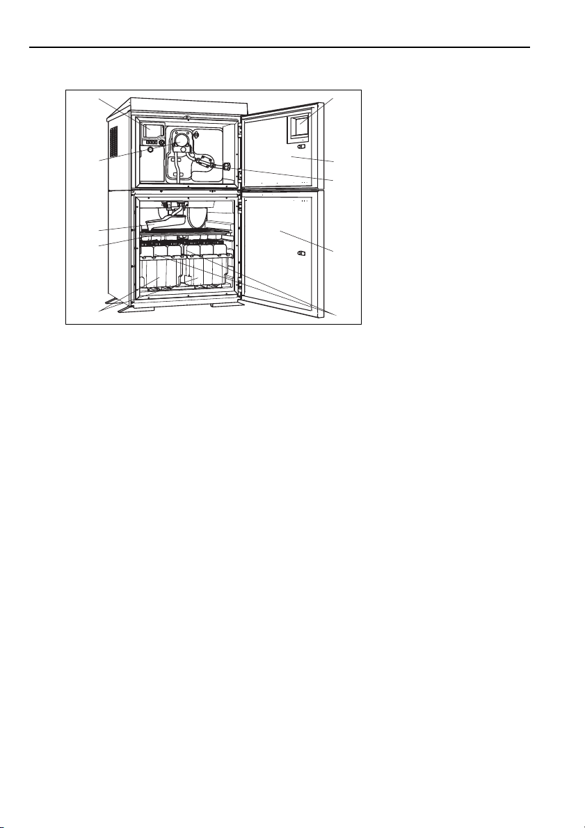
3 Device description . . . . . . . . . . 7
4 Installation . . . . . . . . . . . . . . . . 8
4.1 Incoming acceptance, transport, storage . . . 8
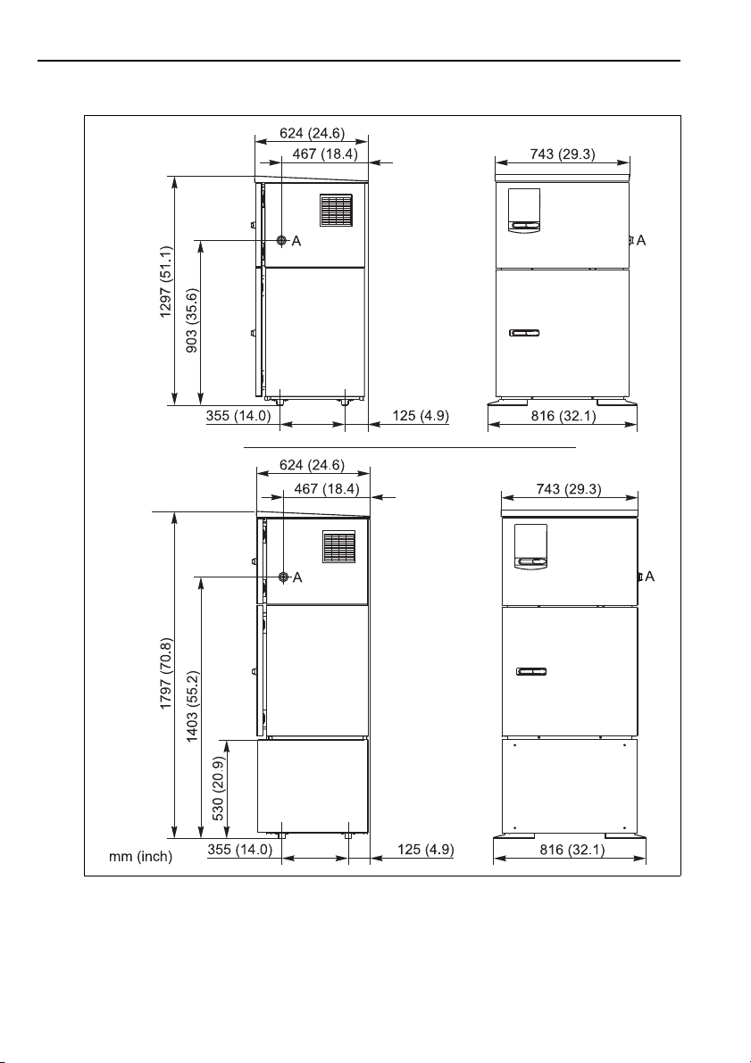
4.2 Installation conditions . . . . . . . . . . . . . . . . 9
4.3 Erecting the sampler . . . . . . . . . . . . . . . . 13
4.4 Sampling with a flow assembly . . . . . . . . . 16
4.5 Post-installation check . . . . . . . . . . . . . . . 17
5 Wiring . . . . . . . . . . . . . . . . . . 18
5.1 Quick wiring guide . . . . . . . . . . . . . . . . . 18
5.2 Terminal assignment for input/output signals
22
5.3 Optional sensor inputs, current outputs and
relays . . . . . . . . . . . . . . . . . . . . . . . . . . . . 23
5.4 Sampler controller . . . . . . . . . . . . . . . . . . 28
5.5 Post-connection check . . . . . . . . . . . . . . . 30
6 Operation . . . . . . . . . . . . . . . . 31
6.1 Display and operating elements . . . . . . . . 31
6.2 Operation concept . . . . . . . . . . . . . . . . . . 32
6.3 Configuration options . . . . . . . . . . . . . . . . 33
7 Commissioning. . . . . . . . . . . . 34
7.1 Function check . . . . . . . . . . . . . . . . . . . . 34
7.2 Switching on the unit . . . . . . . . . . . . . . . . 34
7.3 General settings . . . . . . . . . . . . . . . . . . . . 35
8 Technical data . . . . . . . . . . . . 46
8.1 Input . . . . . . . . . . . . . . . . . . . . . . . . . . . . 46
8.2 Temperature inputs . . . . . . . . . . . . . . . . . 46
8.3 Binary input, passive . . . . . . . . . . . . . . . . . 46
8.4 Analog input, passive/active . . . . . . . . . . . 46
8.5 Output . . . . . . . . . . . . . . . . . . . . . . . . . . . 47
8.6 Current output, active . . . . . . . . . . . . . . . 47
8.7 Relay outputs . . . . . . . . . . . . . . . . . . . . . . 48
8.8 Power supply . . . . . . . . . . . . . . . . . . . . . . 48
8.9 Performance characteristics . . . . . . . . . . . . 49
8.10 Environment . . . . . . . . . . . . . . . . . . . . . . 51
8.11 Process . . . . . . . . . . . . . . . . . . . . . . . . . . . 51
8.12 Mechanical construction . . . . . . . . . . . . . . 52
Index. . . . . . . . . . . . . . . . . . . . 54

Safety instructions Liquistation CSF48
4Endress+Hauser
1 Safety instructions
1.1 Designated use
The Liquistation CSF48 is a stationary sampler for liquid media. The samples are taken
discontinuously using a vacuum or peristaltic pump, distributed to sampling containers and
cooled.
The sampler is designed for use in the following applications:
• Municipal and industrial sewage treatment plants
• Laboratories and Water Conservancy Boards
• Monitoring of liquid media in industrial processes
If the device is used for any purpose other than that described, this poses a threat to the safety
of people and the entire measuring system and is thus not permitted.
The manufacturer does not accept liability for damage caused by improper or non-designated
use.
1.2 Installation, commissioning and operation
Observe the following points:
• Installation, commissioning, operation and maintenance of the measuring system must only
be carried out by trained technical personnel.
The technical personnel must be authorized to perform the tasks by the owner-operator.
• The electrical connection may only be established by an electrical technician.
• The technical personnel must have read and understood these Operating Instructions and
must follow the instructions they contain.
• Prior to commissioning the entire measuring point, check that all connections are correct.
Make sure that electric cables and hose connections are not damaged.
• Do not commission damaged products. Protect them against unintentional startup. Label and
identify the damaged product as defective.
• Faults at the measuring point may only be rectified by authorized and properly trained
personnel.
• If the faults cannot be eliminated, take the products out of service and protect them against
unintentional startup.
• Repairs not described in these Operating Instructions may only be carried out directly at the
manufacturer's or by the Service Organization.
1.3 Operational safety
The product is designed to meet state-of-the-art safety requirements, has been tested and left the
factory in a condition in which it is safe to operate. Relevant regulations and European standards
have been observed.
Connected equipment to the CSF48 shall be in compliance with the relevant safety standard.

Liquistation CSF48 Safety instructions
Endress+Hauser 5
As the user, you are responsible for observing the following safety regulations:
• Installation guidelines
• Local standards and regulations
Electromagnetic compatibility
With regard to electromagnetic compatibility, this device has been tested in accordance with the
applicable European standards for industrial applications.
The electromagnetic compatibility indicated only applies to a device that has been connected in
accordance with the instructions in these Operating Instructions.
1.4 Return
The Liquistation CSF48 is repaired on site.
Contact your Endress+Hauser Service.
1.5 Notes on safety conventions and icons
1.5.1 Warnings
1.5.2 Document symbols
#
Warning!
This symbol alerts you to dangers.
If the warning is not observed, this can result in serious injury to people or damage
to property.
"
Caution!
This symbol alerts you to possible malfunctions resulting from incorrect operation.
If not observed, this could result in damage to property.
!Note!
This symbol indicates important items of information.
È ä 1 This symbol stands for a cross-reference to a certain page (e.g. Page 1).
È å 2 This symbol stands for a cross-reference to a certain graphic (e.g. Fig. 2).
Additional information, tips
Permitted or recommended
Forbidden or not recommended

Identification Liquistation CSF48
6Endress+Hauser
2 Identification
2.1 Device designation
2.1.1 Nameplate
Nameplates can be found:
• On the inside of the upper door
• On the packaging (adhesive label, portrait format)
The nameplate provides you with the following information on your device:
• Order code
• Extended order code
• Serial number
• Device version (software package)
• Input, output values
• Environment
• Activation codes
• Safety notices, warnings
Compare the data on the nameplate with your order.
2.1.2 Serial number and order code
The order code and serial number of your device can be found in the following locations:
• On the nameplate
• On the front page of these Operating Instructions
• In the delivery papers
To find out the version of your device, enter the order code indicated on the nameplate in
the search screen at the following address:
www.products.endress.com/order-ident
2.2 Scope of delivery
The scope of delivery comprises:
• 1 stationary sampler with:
– The ordered bottle configuration
– Optional hardware
• Accessories kit with:
– Connection fitting for suction line with various angles, Allen key
• 1 set of Brief Operating Instructions
(In the preferred language if the "Default operating language" order option is selected.
Otherwise, the Brief Operating Instructions are supplied in English)
• 1 CD-ROM with Operating Instructions in all the languages available
• Optional accessories
If you have any queries, please contact your supplier or local sales center.

Liquistation CSF48 Device description
Endress+Hauser 7
2.3 Certificates and approvals
Declaration of Conformity
The product meets the requirements of the harmonized European standards.
As such, it complies with the legal specifications of the EC directives.
The manufacturer confirms successful testing of the product by affixing to it the 4mark.
3 Device description
A complete sampling unit comprises:
• Liquistation CSF48, with the following depending on the version ordered:
– Controller with display, soft keys and navigator
– Vacuum or peristaltic pump for sampling
– Plastic (PE) or glass sample bottles for sample preservation
– Sample compartment temperature control (optional) for safe sample storage
– Suction line with suction strainer
a0011690
Fig. 1: Example of a Liquistation CSF48, version with vacuum pump
1
2
3
4
5
6
7
8
9
10
Controller
Window (optional)
Dosing compartment door
Suction line connection
Sampling compartment door
Sample bottles, e.g. 2 x 12 PE
1 liter bottles
Bottle trays (depending on the
sample bottles selected)
Distribution plate (depending on
the sample bottles selected)
Distribution arm
Vacuum system, e.g. dosing
system with conductive sample
sensor
12
3
4
5
6
7
9
8
10

Installation Liquistation CSF48
8Endress+Hauser
#Warning!
Danger of injury due to rotating parts
Do not open the cover of the peristaltic pump while the pump is operating.
4 Installation
4.1 Incoming acceptance, transport, storage
• Make sure the packaging is not damaged!
Inform your supplier of any damage to the packaging.
Please keep the damaged packaging until any issues have been resolved.
• Make sure the contents are not damaged!
Inform your supplier of any damage to the contents.
Please keep the damaged goods until any issues have been resolved.
• Check the scope of delivery against the delivery papers and your order to ensure it is complete
and nothing is missing.
• Pack the product in such a way as to protect it reliably against impact and moisture for storage
and transportation. Optimum protection is provided by the original packaging materials. In
addition, the permitted ambient conditions must be observed (see Technical data).
• If you have any queries, please contact your supplier or local sales center.
"Caution!
The top of the sampler may be damaged or torn by incorrect transportation
Always use a lifting truck or a fork-lift to transport the sampler. Never lift the sampler by the top.
a0013207
Fig. 2: Example of a Liquistation CSF48, version with peristaltic pump
1
2
3
4
5
6
7
8
9
10
Controller
Window (optional)
Dosing compartment door
Suction line connection
Sampling compartment door
Sample bottles, e.g. 2 x 12
PE 1 liter bottles
Bottle trays (depending on the
sample bottles selected)
Distributionplate (depending on
the sample bottles selected)
Distribution arm
Peristaltic pump
12
3
4
5
6
7
9
8
10

Liquistation CSF48 Installation
Endress+Hauser 9
4.2 Installation conditions
4.2.1 Dimensions
a0013080
Fig. 3: Dimensions of plastic version of Liquistation CSF48 without and with stand
A Suction line connection

Installation Liquistation CSF48
10 Endress+Hauser
a0013082
Fig. 4: Dimensions of stainless steel version of Liquistation CSF48 without and with stand
A Suction line connection

Liquistation CSF48 Installation
Endress+Hauser 11
4.2.2 Mounting location
1. Correct
The suction line must be routed with a downward slope to the sampling point.
2. Incorrect
The sampler should never be mounted in a place where it is exposed to aggressive gases.
3. Incorrect
Avoid siphoning effects in the suction line.
4. Incorrect
The suction line should never be routed with an upward gradient to the sampling point.
Note the following when mounting the sampler:
• Mount the sampler on a level surface.
• Protect the sampler from additional heating (e.g. from heaters).
• Protect the sampler from mechanical vibrations.
• Protect the sampler from strong magnetic fields.
• Make sure air can circulate freely through the side panels of the housing. Do not mount the
sampler directly against a wall. Allow at least 150 mm (5.91") between the wall and the
sampler on the left and right-hand sides.
• Do not mount the sampler directly over the inlet channel of the wastewater treatment plant.
a0011693
Fig. 5: Mounting conditions

Installation Liquistation CSF48
12 Endress+Hauser
4.2.3 Mechanical connection
Foundation plan
a0012761
Fig. 6: Foundation plan
A Fasteners (4 x M10)
B Cable inlet
C Outlet for condensate and overflow > DN 50
D Sample supply from below > DN 80
– – – Dimensions of Liquistation CSF48

Liquistation CSF48 Installation
Endress+Hauser 13
4.2.4 Connection for sampling
• Maximum suction height:
Vacuum pump: standard 6 m (20 ft), optional 8 m (26 ft)
Peristaltic pump: standard 8 m (26 ft)
• Maximum hose length: 30 m (98 ft)
• Hose connection diameter:
Vacuum pump: internal diameter of 10 mm (3/8"), 13 mm (1/2"), 16 mm (5/8") or
19 mm (3/4")
Peristaltic pump: internal diameter of 10 mm (3/8")
• Intake speed:
> 0.5 m/s (> 1.6 ft/s) for ≤13 mm (1/2") ID, in accordance with EN 25667, ISO 5667
> 0.6 m/s (> 1.9 ft/s) for 10 mm (3/8") ID, in accordance with Ö 5893, US EPA
"Caution!
• Always route the suction line with an upward slope from the sampling point to the sampler
• The sampler should always be located above the sampling point
• Avoid siphoning effects in the suction line
Sampling point
The following conditions must be met at the sampling point:
"Caution!
• Do not connect the suction line to pressurized systems
• Use a suction strainer to catch bigger, abrasive solids that could clog the system
• Immerse the intake hose in the direction of flow
• Take samples at a representative point (turbulent flow; not directly at the base of the channel)
Useful sampling accessories
• Suction strainer:
Catches bigger, abrasive solids that could clog the system
• Immersion assembly:
The adjustable immersion assembly fixes the suction line to the sampling point.
4.3 Erecting the sampler
4.3.1 Connecting the suction line from the side
1. Observe the installation conditions when mounting the sampler.
2. Route the suction line from the sampling point to the sampler.
3. Screw the suction line onto the suction line connection of the sampler.

Installation Liquistation CSF48
14 Endress+Hauser
4.3.2 Connecting the suction line from below
If the suction line is connected from below, the suction line is routed upwards behind the rear
panel of the sample compartment. First remove the rear panel of the dosing chamber and sample
compartment as described in the "Wiring" section.
1. Remove the drain plug from the hose gland located at the back of the sampler base.
2. As illustrated, guide the suction line upwards and through the opening towards the front.
Connecting the suction line in the version with the vacuum pump
1. Unscrew the thread adapter nut (item 3).
2. Unscrew the hose gland (item 4) from the side panel.
3. Fit the hose gland in the fixing clamp (item 2) as illustrated.
4. Screw the hose tight from above.
5. Attach the hose adapter supplied to the suction line and screw it onto the hose gland from
below.
6. Insert the dummy plugs supplied.
a0013704
Abb. 7: Sample supply from below
1
2
Gland for the suction line
Suction line
1
2

Liquistation CSF48 Installation
Endress+Hauser 15
Connecting the suction line in the version with the peristaltic pump
1. Unscrew the thread adapter nut (item 3) and the hose gland (item 4) from the side panel.
2. Unscrew the small thread adapter nut (item 1) and remove the hose.
3. Connect the suction line from below as illustrated.
4. Insert the dummy plugs supplied.
a0013707
Abb. 8: Vacuum pump with suction line connected at the
side
1 Hose
2 Fixing clip for hose gland
3 Thread adapter nut
4 Hose gland
a0013708
Abb. 9: Suction line connected from below
a0013705
Abb. 10: Peristaltic pump with suction line connected at
the side
1 Small thread adapter nut
2 Hose
3 Thread adapter nut
4 Hose gland
a0013706
Abb. 11: Suction line connected from below
1Suctionline
1
2
3
4
1

Installation Liquistation CSF48
16 Endress+Hauser
4.4 Sampling with a flow assembly
The sample is taken directly from the flow assembly which is installed in the sampler stand.
The flow assembly is used when sampling in pressurized systems, e.g.:
• Containers located at a higher level
• Pressurized pipes
• Pumping with external pumps
The flow rate should be 1000 to 1500 l/h.
"Caution!
The outlet of the flow assembly must be unpressurized (e.g. drain, open channel).
a0013127
Fig. 12: Flow assembly
1
2
3
Flow assembly inlet: ¾"
Sample connection
Flow assembly outlet: 1¼"

Liquistation CSF48 Installation
Endress+Hauser 17
Use the ball valve 1 to set the flow rate to 1000 l/h ... 1500 l/h. When the sampling cycle
begins, you can use one of the relay outputs to control and open valve 2. The medium flows
through the pipe and the flow assembly into the outflow. When a settable delay time has elapsed,
the sampler takes the sample directly from the flow assembly. Valve 2 is closed again once the
sample has been taken.
!Note!
Valves 1 and 2 are not contained in the scope of delivery.
4.5 Post-installation check
• Make sure the suction line is securely fitted to the sampler.
• Perform a visual inspection to ensure the suction line is routed correctly from the sampling
point to the sampler.
• Make sure the distribution arm is correctly mounted.
a0013458
Fig. 13: Example: Sampling from pressure piping
1 Ball valve 1
2Valve2

Wiring Liquistation CSF48
18 Endress+Hauser
5 Wiring
#Warning!
• The electrical connection may only be established by an electrical technician.
• The electrical technician must have read and understood these Operating Instructions and
must follow the instructions they contain.
•Prior to beginning any wiring work, make sure voltage is not applied to any of the cables.
"Caution!
• The device does not have a power switch.
The customer must provide a protected circuit breaker in the vicinity of the device. This must
be a switch or a power-circuit breaker and must be labeled as the circuit breaker for the
device.
• The protective earth connection must be established before any other connections are made.
A disconnected protective ground can be a source of danger.
• An overload protection unit is required for the power supply cable.
• The device versions for 24 V shall be powered from an energy source which is separated from
hazardous live by double or reinforced insulation at the source of the supply.
5.1 Quick wiring guide
5.1.1 Routing the cables
• Route the cables behind the rear panel of the sampler so that they are properly protected.
• 8 cable glands are available for the cable entries.
• Plan a cable length of approx. 1.7 m (5.6 ft) from the foundation to the terminal connection.
5.1.2 Cable types
• Power supply: e.g. NYY-J; 3-wire; max. 2.5 mm2
• Analog, signaling and transmission cables: e.g. LiYY 10x0.34 mm2
!Note!
The terminal connection is located under an additional protective cover in the upper rear section
of the device. For this reason, the rear panel of the device must be removed to connect the power
supply prior to commissioning.

Liquistation CSF48 Wiring
Endress+Hauser 19
5.1.3 Removing the rear panel of the dosing compartment
Open the dosing compartment door to remove the rear panel of the dosing compartment.
5.1.4 Removing the rear panel of the sampling compartment
a0012803
Fig. 14: Screw above the dosing compartment
1 To release the rear panel, turn clockwise with an
Allen key (5 mm)
a0012826
Fig. 15: Lift up the top rear panel and pull it back to
remove it
a0012825
Fig. 16: Remove the bolts on the bottom left and right on
the rear of the dosing compartment
a0012824
Fig. 17: Push up the lower rear panel to remove it
CLOSE OPEN
1
1.
2.

Wiring Liquistation CSF48
20 Endress+Hauser
5.1.5 Removing the cover on the power unit
#Warning!
Make sure the device is disconnected from the power source before you remove the cover of the
power unit.
a0012831
Fig. 18: Removing the cover on the power unit
1. Release the screw with an Allen key (5 mm)
2. Remove the cover of the power unit from the front
Other manuals for Liquistation CSF48
13
Table of contents
Other Endress+Hauser Sampler manuals

Endress+Hauser
Endress+Hauser Liquistation CSF33 User manual

Endress+Hauser
Endress+Hauser Liquistation CSF34 Technical specifications

Endress+Hauser
Endress+Hauser ASP Inline User manual

Endress+Hauser
Endress+Hauser Liquistation CSF28 User manual

Endress+Hauser
Endress+Hauser asp-port d 2 se User manual

Endress+Hauser
Endress+Hauser Liquiport 2010 CSP44 User manual

Endress+Hauser
Endress+Hauser Liquiport 2010 CSP44 User manual

Endress+Hauser
Endress+Hauser Liquistation CSF28 Technical specifications

Endress+Hauser
Endress+Hauser ASP Station 2000 peristaltic User manual

Endress+Hauser
Endress+Hauser asp-station a 2 User manual