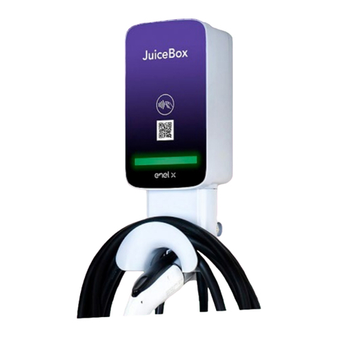
Enel X JUICEBOX PRO User guide

JUICEBOX PRO &
JUICEBOX PLUS
Installer Manual

In this document
Purpose of this document 6
Installation Process 6
Document Structure 6
A. JuiceBox Pro & JuiceBox Plus - Installation Manual 8
1 JuiceBox 9
1.1 Features 10
1.2 Dimensions 11
2 Impoant safety information 12
2.1 Electric and electronic equipment end of life user’s information 12
3 Package Contents 13
4 Tools Needed 14
5 Installation Prerequisites 15
5.1 Protections 16
5.2 Power and signal cables 18
5.3 JB4Installers App 18
5.4 JuicePass App 18
6 Standard Installation 19
7 Special Installation Cases 36
7.1 Three phase JuiceBox installed on a Single-phase or Bi-phase supply system 36
7.2 Other special cases 36
8 Firmware Update 36
9 Load Optimization Pro 37
10 JuiceBox Commissioning through the JuicePass App 38
10.1 Commissioning via Cellular Connectivity 38
10.2 Commissioning via Wi-Fi Connectivity 44
10.3 Procedure for Unpairing the JuiceBox from the JuicePass Account 51
11 Charging Test 53
11.1 Charging in Unlock to Charge mode 54
11.2 Charging in Connect&Charge Mode 56
11.3 Recording the Charging Session in the Charging history 57

11.4 Checking Charging Power 58
11.5 Testing Load Optimization Pro 58
12 LED indicator 59
B. JuiceMeter- Installation Manual 60
1 JuiceMeter 61
1.1 Electric and electronic equipment end of life user’s information 61
2 Single-phase JuiceMeter 62
2.1 Features 62
2.2 Installation 64
2.3 JuiceBox connection diagrams 68
3 Three-phase JuiceMeter 70
3.1 Features 70
3.2 Installation 72
3.3 JuiceBox connection diagrams 77
C. JuiceBox Pro & JuiceBox Plus - JB4Installers App Manual 80
1 Purpose of the Manual 81
2 Pre-requisites 81
3 Login 81
4 New rmware download 83
5 Loading the JuiceBox serial on the app 84
6 Connecting the JuiceBox to the App 86
7 Firmware Update 89
8 JuiceBox Connectivity Check for Cellular Versions 92
9 JuiceBox Conguration 94
9.1 Conguration of the “Supply System” Parameter 94
9.2 Wi-Fi Conguration 95
9.3 JuiceMeter Conguration (for JuiceBox Pro) 96
9.4 Conguration of the JuiceBox in Standalone Mode 97
9. 5 Conguration of the JuiceBox in Absence of Cellular Connectivity 98
9.6 Conguration of the JuiceBox in case of installation on the IT network or in absence

of neutral 102
9.7 GPD disabling procedure 102
10 Viewing JuiceBox Diagnostics 103
D. JuiceBox Pro & JuiceBox Plus - JuiceBox Web Manager manual 104
1 Procedure for accessing the Web Manager tool 105
2 Procedure for seing the JuiceBox in “standalone” mode in case of lack of
connectivity and for commissioning 106
3 Seing the JuiceBox access mode, power, and Supply System 107
4 Association of the JuiceBox with JuiceMeter 110
5 Wi-Fi 113
E. JuiceBox Pro & JuiceBox Plus - Procedure for installing the external
protection release solution for JuiceBox with control board 114
1 Introduction 115
2 Procedure for installing the external protection release solution 115
3 Composition of Siemens Protection Kits 117
F. JuiceBox Pro & JuiceBox Plus - HW GPD Deactivation Procedure 119
1 GPD Deactivation Procedure 120
G. JuiceBox Pro & JuiceBox Plus - What-if Manual - Special installation
cases 123
1 Purpose of the Manual and Method 124
2 List of Special Installation Cases 125
2.1 Data network signal with SIM is insucient 126
2.2 Single-phase IT power grid 127
2.3 Customer smaphone connectivity not adequate 128
2.4 Lockable garage with shuer (or other type) that weakens signal 129
2.5 Single-phase TT/TN power grid 130
2.6 Three-phase TT/TN power grid 131
2.7 Single-phase TT electrical grid without neutral 132
2.8 JuiceBox with control board in Italy and in Holland 132

2.9 EV ready Installation 133
2.10 JuiceBox with Load Optimization Pro (without photovoltaics) 133
2.11 JuiceBox with Load Optimization Pro (with photovoltaics) 134
2.12 Customer's vehicle not available during installation 134
2.13 Renault Zoe, Sma 22 kW, Twingo Electric 135
2.14 Load Optimization Pro with transformer 135
H. JuiceBox Pro & JuiceBox Plus - Installer checklist 136
1 Installer checklist example 137

6
REV. 1
Purpose of this document
The purpose of this manual is to provide the installer with all the information necessary for
the correct installation and commissioning of the JuiceBox Pro and JuiceBox Plus charging
stations.
Installation Process
The following process is recommended to carry out the installation operations:
1. Please read this Installer Manual.
2. Carry out a feasibility inspection at the installation site by lling out a checklist provided
for this purpose by Enel X (see Installer Checklist example). This checklist allows you to
nd out whether you can proceed with standard installation (see Standard Installation)
or whether you need to follow the special installation procedures (see What-if Manual);
3. Obtain tools, materials, apps, and everything needed for installation (see Tools Needed);
4. Proceed with installation, commissioning, congurations, testing, and acceptance test.
Document Structure
The manuals that comprise this document are listed below.
DOCUMENT
SECTION MANUAL TOPIC
Section A JuiceBox Pro & JuiceBox Plus
Installation Manual
Physical installation of the JuiceBox,
introduction to congurations,
commissioning via JuicePass app,
and charging test
Section B JuiceMeter Installation
Manual
Physical installation of single-phase
and three-phase JuiceMeter device
to enable Load Optimization Pro
feature (available only with JuiceBox
Pro)

7
REV. 1
Section C JuiceBox4Installer App
Manual
Guide for the use of the
"JuiceBox4Installer" app, necessary
to carry out the JuiceBox
conguration activities (if not carried
out with the JuicePass app) and
JuiceMeter
Section D JuiceBox Web Manager
Manual
Guide for the use of the "JuiceBox
Web Manager" web app, which can
be used by all users to carry out the
JuiceBox conguration activities (if
not carried out with the JuicePass
app) and JuiceMeter
Section E
Procedure for installing the
external protection release
solution for JuiceBox with
control board
Guide to install protection
components for JuiceBox equipped
with control board
Section F HW GPD Deactivation
Procedure
Guide to disable the Ground
Presence Detector in the JuiceBox
to be followed in the cases indicated
in this manual
Section G What-if Manual - Special
installation cases
Procedures to be followed after
verication of a non-standard
installation case
Section H Installer checklist example
Checklist to be lled in during
the inspection to determine the
JuiceBox installation method
(standard or procedures for special
cases)

8
REV. 1
A. JuiceBox Pro & JuiceBox Plus -
Installation Manual

9
REV. 1
1 JuiceBox
JuiceBox Pro and JuiceBox Plus charging stations are available in two versions.
JUICEBOX CABLE VERSION (1):
1Cable
2RFID reader
3LED indicator
4Connector
1RFID reader
2LED indicator
3Socket
JUICEBOX SOCKET VERSION (2):
The JuiceBox Pro diers from the JuiceBox Plus by the possibility to enable the Load
Optimization Pro feature, which allows the Customer to always charge at the maximum
available power without triggering the meter. The activation of this function requires the
installation of an additional device, the JuiceMeter.
>JuiceBox Pro installation: hardware installation of the JuiceBox, hardware installation of
the JuiceMeter, conguration, testing and acceptance test
>JuiceBox Plus installation: hardware installation of the JuiceBox, conguration, testing
and acceptance test

10
REV. 1
1.1 Features
Output power
Single-phase
Up to 3.7 kW, 16 A
Up to 7.4 kW, 32 A
Three-phase Up to 22 kW, 32 A
Input voltage
Single-phase 230 VCA
Three-phase 400 VCA
Charging mode Mode 3
LED Dynamic LEDs indicating charging status
Protezione
IP55, IK08
The JuiceBox has an internal detector for DC fault
currents above 6 mA.
The following external protections are required:
>Type A residual current device (RCD)
>Curve C Miniature Circuit Breaker (MCB)
NOTE:
Some countries may require the installation of a Type B
RCD instead of the type A.
Operating temperature From -40 °C to +60 °C
Standards and
ceications
IEC 61851-1
CE Ceication
JuiceBox with control board: The cable version JuiceBox to be installed in Italy and Holland
has the control board.
JuiceBox to be installed according to EV ready requirements also are equipped with the
control board.

11
REV. 1
1.2 Dimensions
NOTE:
All dimensions are in mm.
>Base (mounting holes circled in red)
>JuiceBox cable version
>JuiceBox socket version and JuiceBox socket version with control board

12
REV. 1
2 Impoant safety information
Read all safety information before installing the product.
>WARNING: Do not leave this unit unaended if children are nearby.
>WARNING: Do not put your ngers into the electric vehicle connector.
>WARNING: Do not use this product if the exible power cord is frayed, has damaged
insulation, or shows other signs of damage.
>WARNING: For use with electric vehicles only.
>WARNING: Do not use this unit with an extension cord.
>WARNING: Do not remove the cover or aempt to open the housing. There are no user-
serviceable pas inside. Refer all servicing to qualied service personnel.
>WARNING: Install and use the JuiceBox away from ammable, explosive, irritating, or
combustible chemicals, materials, or vapors.
>WARNING: Do not turn on the JuiceBox outside of its operating temperature range of
-40 °C to +60 °C.
>WARNING: This unit is intended only for electric vehicles that do not require ventilation
while charging.
>WARNING: This product must be grounded. In the event of a failure or breakdown,
grounding ensures a path of least resistance for electrical current to reduce the risk of
electric shock.
>WARNING: Improper connection of the equipment-grounding conductor may result
in a risk of electric shock. If you are unsure whether the product is properly grounded,
consult a qualied electrician or service technician.
2.1 Electric and electronic equipment end of life user’s
information
Pursuant to local laws and regulations and according to a.14 of Directive 2012/19 / EU
on waste electrical and electronic equipment (WEEE), crossed-out waste bin symbol on
equipment or on its packaging means that the product shall be disposed of
separately from household waste. When this product reaches its end of life, take
it to a collection point designated by local authorities. The separate collection
and recycling of product at the time of disposal will help to conserve natural
resources and ensure that it is recycled in a manner that protects human health
and the environment.

13
REV. 1
JuiceBox charging station with M3-0.5 x
12 mm screws (x3) and washers (x3)
Base with M5 x 50 mm screws (x4) and
washers (x4)
Terminal block
Dowels M8 x 40 mm (x4)
Ferrite
Terminals (x5)
NOTE:
These terminals must be used only
when using cables with a cross section
of 4 mm2and 6 mm2
Wateight gasket for external antenna
NOTE:
This item must be installed in case you
need an external antenna.
3 Package Contents

14
REV. 1
4 Tools Needed
>Phillips screwdriver.
>Flat screwdriver.
>Pencil or marker.
>Hex wrench size 4.
>Wrench size 8.
>Phillips screwdriver (dynamometric 1.3 Nm).
>Crimping tool.
>Wire stripper.
>Electrician's scissors.
>Silicone.
>Android smaphone (required for conguration tasks).
>Measuring tape and level.
For masonry or concrete buildings:
>Hammer.
>Drill bit for M8 wall plugs.
Gasket kit for single-phase JuiceBox
installation with 10 mm2cross section
cables
>Gasket 6 for PE
>Gasket 2/6 for L1 and N/L2
Gasket kit for three-phase JuiceBox
installation with 10 mm2cross section
cables
>Gasket 6 for PE
>Gasket 4/6 for L1, L2, L3, N
Gasket for installation of connection cables
with control board (included only in versions
with control board)
>Gasket 2/3

15
REV. 1
DISTRIBUTION NEUTRAL VOLTAGE
Single-phase
TT
Yes 230 VAC
Three-phase Yes 400 VAC
Single-phase
TN-S
TN-C-S
Yes 230 VAC
Three-phase Yes 400 VAC
Single-phase IT No 230 VAC
5 Installation Prerequisites
The JuiceBox must be installed in accordance with the following specications:
> Within a useful distance of the vehicle's charging po.
> For Wi-Fi enabled units: Within range of local Wi-Fi network (suppos IEEE 802.11b/g/n
at 2.4 GHz).
> For units equipped with a cellular data connection (JuiceBox Pro Cellular and JuiceBox
Plus Cellular): in an area with good mobile data network coverage. If the reception is
not sucient, an external antenna will also need to be installed and connected to the
JuiceBox. The optimal signal strength is greater than or equal to -80 dBm (e.g. -75 dBm is
greater than -80 dBm, because of the minus sign). If the measured signal is less than -80
dBm (e.g. -85 dBm) could be necessary to install a dedicated external antenna. Anyway,
also if an antenna is installed it could not be sucient.
NOTE:
JuiceBox Pro, Pro Cellular, Plus and Plus Cellular all have Wi-Fi connectivity, except in Italy
and Spain. In these two countries, only Cellular connectivity is available and currently only
JuiceBox Pro Cellular and JuiceBox Plus Cellular are installed.
NOTE:
The system shall be installed in accordance with applicable local codes.
The JuiceBox is compatible with the networks in the following table:

16
REV. 1
JUICEBOX MINIATURE CIRCUIT
BREAKER
RESIDUAL CURRENT
DEVICE
Single-
phase
Up to 3.7 kW, 16 A
>Curve C
>ICC: 10 kA
>In: 20 A
>Poles: 2
>Type A
>Id: 30 mA
>In: 20/25 A
>Poles: 2
Up to 7.4 kW, 32 A
>Curve C
>ICC: 10 kA
>In: 40 A
>Poles: 2
>Type A
>Id: 30 mA
>In: 40 A
>Poles: 2
Three-
phase Up to 22 kW, 32 A
>Curve C
>ICC: 10 kA
>In: 40 A
>Poles: 4
>Type A
>Id: 30 mA
>In: 40 A
>Poles: 4
5.1 Protections
The installation of the JuiceBox should include dedicated protection devices. Below are the
recommended protections for the installation:
NOTE:
MCB shall have a magnetic throughput energy I2t ≤ 60000 A2s
WARNING
Some electric vehicles require the Neutral (N) on the charging station to have direct
contact with the Ground. This has an impact on charging in case of IT networks. In
this case, a transformer must be installed upstream of the RCD and MCB and the
JuiceBox to have a local TN system.

17
REV. 1
Control board location Clean contact on control board
The characteristics of the clean contact of the control board are as follows:
>The contact is NO (normally open).
>The maximum voltage the contact can withstand is 60V.
>The maximum sustained current in continuous mode is 100 mA.
>The cross-section of the connecting cables to the contact is between 1 mm2
and 1,5 mm2.
>The diameter of the connecting cables is between 3 mm and 3.5 mm.
The change in status of this contact is used to control an external release solution
(motor with MCB adapter). For more information on the installation of the release
device, please refer to “Procedure for installing the release solution for external
protections for JuiceBox cable version and socket version with control board”.
JUICEBOX WITH CONTROL BOARD
JuiceBox with control board are equipped with a clean contact on the board itself that
changes its status from NO (normally open) to closed in case of a fault on the internal
contactor of the JuiceBox. In this case, the control board is used to command the
opening of a protection (dierential or magnetothermal) to cut o the power supply
circuit.

18
REV. 1
5.2 Power and signal cables
The choice of cross-sections, insulating materials and composition of the power cables
shall be made in line with the size of the switches and in accordance with local standards
in force.
The following table shows the minimum recommended cross sections for a standard
installation using copper cables.
JUICEBOX MINIMUM SECTION
Single-
phase
Up to 3.7 kW, 16 A 4 mm2
Up to 7,4 kW, 32 A 6 mm2
Three-
phase Up to 22 kW, 32 A 6 mm2
5.3 JB4Installers App
Enel X paners will need to install the JB4Installers app on their smaphone to peorm
JuiceBox conguration and diagnostic tasks. To use the app, they will need to receive
authorization from Enel X and complete a registration process. Please refer to the
JB4Installers App Manual for more information.
5.4 JuicePass App
Enel X paners will need to install the JuicePass app on their smaphone to peorm JuiceBox
conguration tasks. JuicePass is available on the iOS App Store e Google Play. For more
information, see section 10 of this manual.
NOTE:
The maximum conductor cross-section of cables that can be used for JuiceBox is 10 mm2.
In this case the maximum conductor diameter shall be 4 mm.
JUICEBOX WITH CONTROL BOARD:
JuiceBox with control board require signal cables with section between 1 and 1.5 mm2and
external diameter between 2.5 and 3.5 mm.

19
REV. 1
6 Standard Installation
The following is the standard installation procedure, valid for all versions of JuiceBox in this
manual. The procedure also includes optional steps, which must be carried out only in the
following cases:
>Installation of a JuiceBox with control board.
>Installation of an external antenna.
NOTE:
The JuiceBox must be installed by a qualied electrician.
1. Make sure no voltage is applied to the input cable.
WARNING
Do not continue this procedure until you are ceain that no voltage is present at the
input cable.
2. When installing 4 mm2and 6 mm2cross-section cables, install the terminals on the input
cable wires with the crimping tool.
NOTE:
When installing 10 mm2cables, strip only the cables, do not install the terminals.

20
REV. 1
3. Remove the gasket block cover using a 4mm hex wrench.
4. Identify the nut screws that secure the gasket block. Hold the nut in place with a size 8
wrench, then loosen the screw with a size 4 hex wrench.
Other manuals for JUICEBOX PRO
2
This manual suits for next models
1
Table of contents
Other Enel X Batteries Charger manuals
Enel X
Enel X JuicePump 150 User manual
Enel X
Enel X JuiceBox User manual
Enel X
Enel X Waypole User manual
Enel X
Enel X Way JuiceBox OpenPay User manual

Enel X
Enel X JUICEBOX PRO User manual
Enel X
Enel X Way Next Gen JuiceBox User manual

Enel X
Enel X Waypole User manual

Enel X
Enel X JuicePump User manual
Enel X
Enel X Way JuiceBox User manual

Enel X
Enel X Waybox Pro User guide
