Enel X Waypole User manual

User Manual
Waypole
ENGLISH


3
1. Purpose
The purpose of this document is to describe how to use the equipment named Enel X Way
Waypole™.
2. Field of application
It is used to document how to use such equipment as pa of an Electric Vehicle Charging
System.
3. Denitions/Abbreviations
PS 4G POLE STATION 4G or Enel X Way Waypole™
JP POLE STATION 4G or Enel X Way Waypole™
EV ELECTRIC VEHICLE
RH RIGHT
LH LEFT
CM COMMUNICATION MODULE
CP CONTROL PROCESS
4
4. Waypole
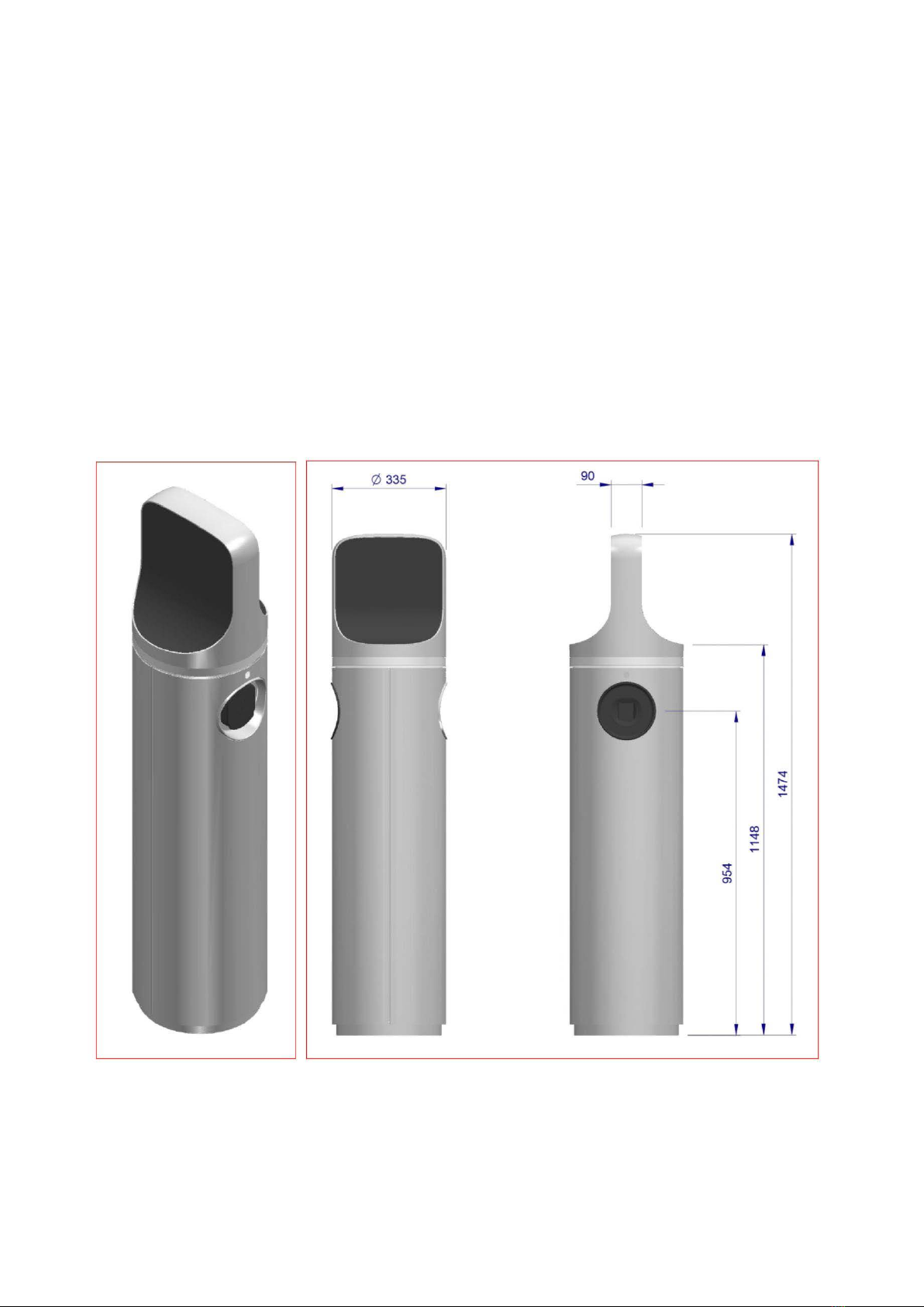
4.1 Dimensions
There are several versions of the Enel X Way Waypole™:
1. Three-phase/Three-phase with 2 T2 sockets;
2. Single-phase/Three-phase with 1 T3a socket and 1 T2 socket;
3. Single-phase/Single-phase with 2 T3a sockets.
These variants aect the user, especially regarding the type of power supply cable provided with
the Electric Vehicle.
3⁄4 View Outline and dimensions in mm

5
4.2 Specications
VOLTAGE 400 Vac Three-phase
FREQUENCY 50 Hz
POWER SUPPLY
CHARGING DATA
SINGLE-
PHASE
CHARGING
Type 3A socket with 4 contacts L, N, EARTH + Pilot
Maximum power 3,7 kW
Maximum current 16 A
Thermal-magnetic protection
In= 16 A
Icn = 10kA
Type “D”
Residual Current Protection
Current = 0.03 A
Protection type B
THREE-
PHASE
CHARGING
Type 2 socket with 7 contacts R, S, T, N, EARTH + Pilot +
Proximity
Maximum power 22kW
Maximum current 32A
Thermal-magnetic protection
In= 40 A
Icn = 10 kA
Type “D”
Residual Current Protection
Current = 0.03 A
Protection type B

6
GENERAL
STANDARDS
AMBIENT TEMPERATURE -25°C to 50°C
RELATIVE HUMIDITY 5% to 95%
ATMOSPHERIC PRESSURE 860hPa÷1060hPa
PROTECTION LEVEL IP54
>EN61851-1
>EN61851-22
>EN62196-1
4.3 Functionality
The Waypole was designed for charging “Class I” Electric Vehicles.
It supplies 230 Vac single-phase with a maximum power of 3.7 kW and/or 400 Vac three-
phase with a maximum power of 22 kW.
It works in “Mode 3” and is connected to the vehicle as described in the EN61851-1 standard
(Ed. 3.0) under “Case A” or “Case B”.
CLASS I
An Electric Vehicle the protection of which against electric shocks,
when connected to an a.c. supply network (mains), does not rely on the
functional insulation, but includes supplementary safety measures. This
shall consist of connecting all exposed conductive
pas to the vehicle eah terminal.
MODE 3 Direct connection of the Electric Vehicle to the mains power. Any baery
chargers are installed directly on the vehicle.
CASE A Connection of an Electric Vehicle to an a.c. supply utilizing a cable and
plug permanently aached to the Electric Vehicle.

7
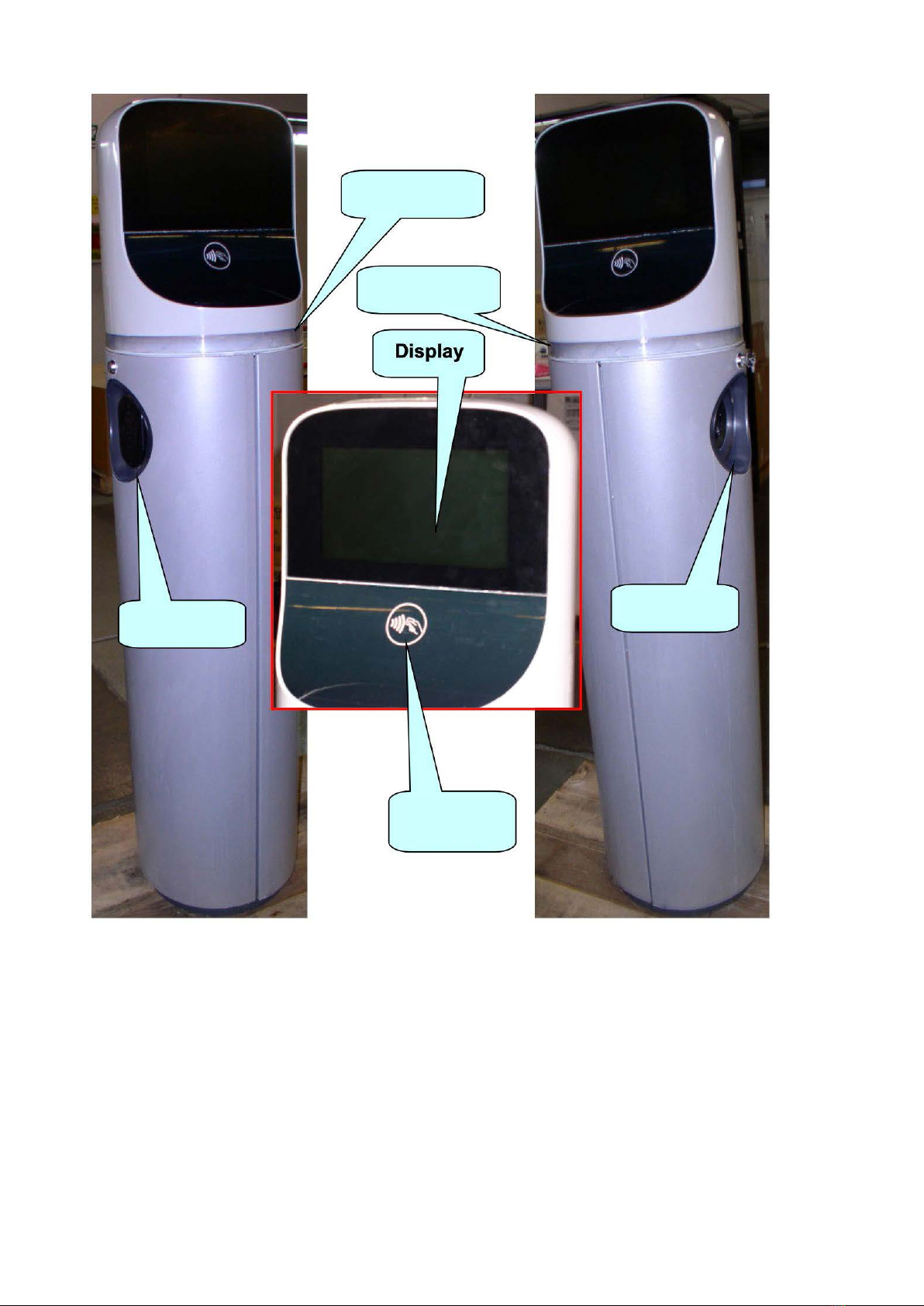
4.4 The user inteace
The Waypole is equipped as described below.
DESCRIPTION USE
Display Provides the user with information
User Card Reader Reads the user’s card
RH indicator Always lit
LH indicator Always lit
RH socket RH supply point
LH socket LH supply point
CASE B Connection of an Electric Vehicle to an a.c. supply utilizing a detachable
cable assembly with a vehicle connector and a.c. supply equipment.
NOTE: The user should note that the ”pilot control wire” in the power supply
circuit prevents the Waypole from supplying power until the plug is fully inseed
into the socket.
8
RH indicator
LH indicator
RH socket
LH socket
Card
Reader

9
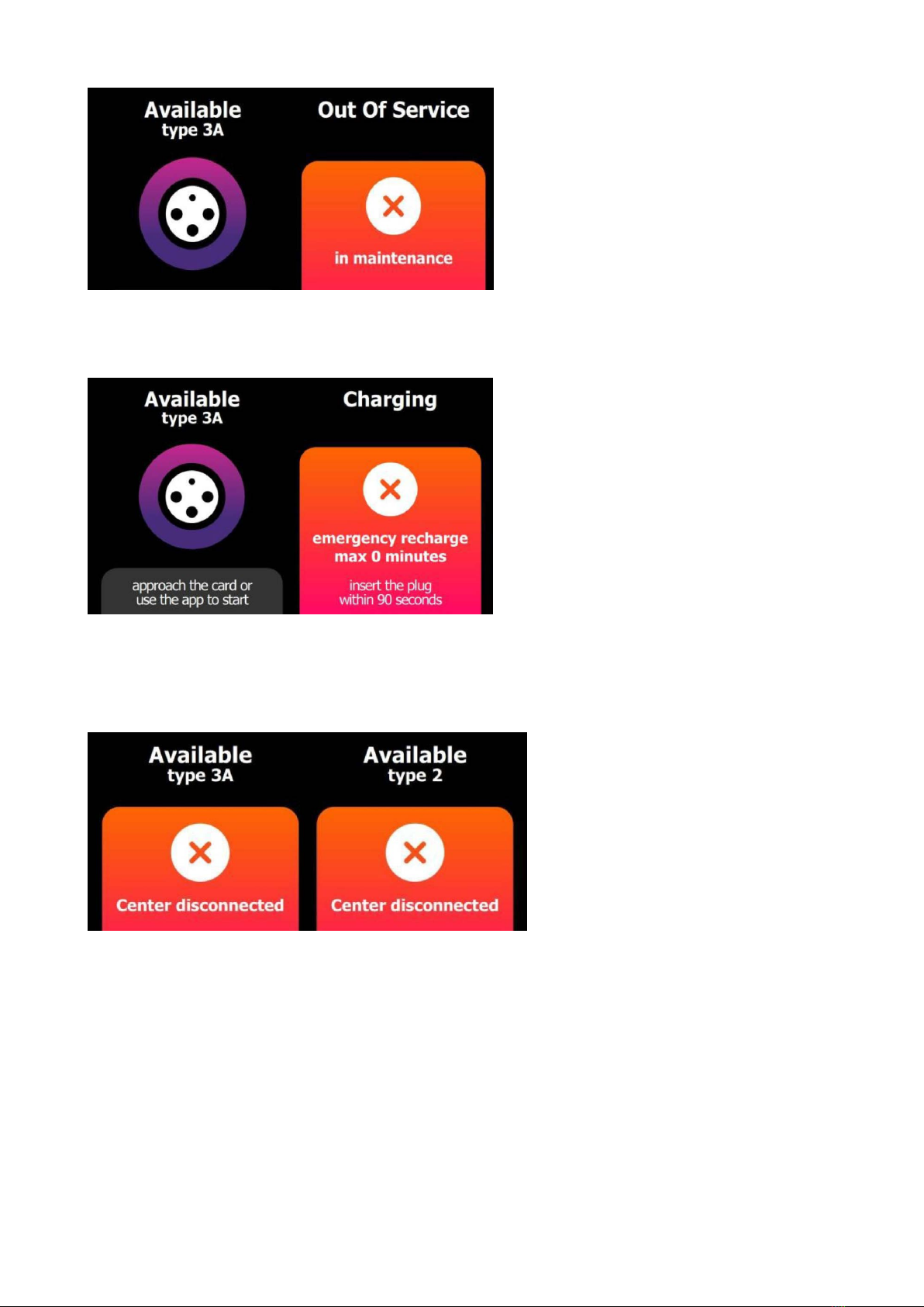
4.5 Operation
4.5.1 INTRODUCTION
The Waypole control system manages both the RH and LH sockets in parallel, making it
possible to charge two EVs simultaneously.
4.5.2 CHARGING
The display initially looks like this (assuming that there is no charging in progress):
First, users must identify themselves with the RFID card or appropriate APP.
Bring the RFID card up to the reader and wait for it to be accepted. When this happens, the
following screen will appear on the display for a moment:

10
It is then necessary to inse the plug on the charging cable into the chosen socket within
90 seconds (timeout).
The following screens will “alternate” cyclically.
When only 30 seconds remain, the screen will show a numerical countdown (see the red
arrow).
If the system accepts the RFID card, this appears:

11
As soon as charging stas, the screen will show the kWh supplied on the side in which the
plug is inseed, e.g. RH.
If a second valid RFID card is brought up to the reader (or using an appropriate APP) while
the charging just staed is in progress, the following appears in sequence:
It is now necessary to inse the plug on the charging cable into the LH socket (last available)
within 90 seconds (timeout). The screen with a socket that appears/disappears will be
shown only for the LH side.
As soon as charging stas, the display will show the kWh supplied on the LH side in which
the plug is inseed.
Suppose we inse the plug into the RH side; the display will show:

12
Suppose that the charging on the RH side is stopped by bringing the card up to the RFID
reader (or using the appropriate APP); the following will appear in sequence:
The system will stop supplying power from the side corresponding to the RFID card used,
and gives a summary of the Wh supplied during charging. It is now necessary to extract the
plug on the RH side.
The RH plug will become available for charging again.

13
Lastly, suppose that the charging on the RH side is also terminated by bringing the card up
to the RFID reader; the following will appear in sequence:
The system will stop supplying power from the side corresponding to the card used, and
gives a summary of the Wh supplied during charging. It is now necessary to extract the plug
on the LH side.
Both sockets are now available for charging again.
4.5.3 EXCEPTIONS
During the activities described in the previous paragraph, the system may respond to the
user in an unexpected manner. In this case, the user must peorm specic actions to solve
the setback, if possible.
NOTA: Obviously, exceptions related to user card “validation” by the centre do not
regard the APP, which communicates directly with it.

14
>Charging interrupted -> Remove the plug to nish.
>Charging interrupted -> Bring the card close or use the App to end.
>Standby: charging suspended by the centre -> Wait for charging to continue.
>Standby: charging suspended by the EV (baeries overheated) -> Wait for charging to
continue.
>Standby: charging suspended by the EV (baeries charged) -> Remove the plug.
15
>Plug inseed without card validation -> Remove the plug
>(105:) Problems with the centre -> Not possible to continue.
>Communication problems with the centre -> Charging will end when the indicated time
expires if the communication problems are permanent (e.g. 15 minutes).

16
THE MESSAGES ARE CODED AS FOLLOWS
CODE MESSAGE SIGNIFICANCE
100 Invalid card Not possible to continue.
101 Validation not successful Not possible to continue.
103 Validation failed Problems with the centre - > Not
possible to continue.
105 Centre disconnected Communication problems with the
centre -> Not possible to continue.
106 Session limit reached Not possible to continue.
107 Unrecognised error Not possible to continue.
108 CU not registered Problems with the centre -> Not
possible to continue.
109 Commissioning error Not possible to continue.
200 Unauthorised card Card problems -> Not possible to
continue.
201 Expired card Card problems -> Not possible to
continue.
202 Unrecognised card Card problems -> Not possible to
continue.
203 Unregistered card Card problems -> Not possible to
continue.
204 Card not accepted Card problems -> Not possible to
continue.
205 Card accepted Card problems -> Not possible to
continue.
206 Credit nished Invalid card -> Not possible to
continue.
207 Card already being used Not possible to continue.
208 Invalid contract Invalid card -> Not possible to
continue.

17
209 No associated stakeholder Invalid card -> Not possible to
continue.
210 Incorrect CU type Invalid card -> Not possible to
continue.
211 Incorrect POD Invalid card -> Not possible to
continue.
212 Out of province Invalid card -> Not possible to
continue.
214 Socket booked Not possible to continue.

18
Appendix A
Error codes
Messages appear on the display together with an “Error Code” (see the blue arrow) if errors
occur during normal Waypole operation.
The table below lists all the possible error codes with their meanings and possible solutions.
X X Y Y Z Z EVENT SOLUTION
0# # # # # Pole Station Identier --
4# # # # # The system is powering
down
Restore the power
supply
#2# # # # CM is not operational Switch the PS o and on
again
#4# # # # Internal ash memory full Ask the centre to erase it
#6# # # # CM is not operational +
Internal ash memory full
Switch the PS o and on
again + Ask
the centre to erase
#8# # # # No mains power Restore the power
supply

19
#A# # # # CM is not operational +
No mains power
Switch the PS o and on
again
#E# # # #
CM is not operational +
Internal ash memory full
+ No mains power
Switch the PS o and on
again + Ask
the centre to erase
# # 1###
Communication problem
with the card
reader
Switch the PS o and on
again
# # 2###Communication problem
with the meter
Switch the PS o and on
again
# # 4###Equipment opening
detected (Antitamper) Ask the centre for a reset
# # 5###
Communication problem
with the card reader
+ Equipment opening
detected (Antitamper)
Switch the PS o and on
again + Ask the centre
for a reset
# # # # 1#
Communication problem
with the socket
board
Switch the PS o and on
again
# # # # 2#
Internal residual current
device or circuit breaker
tripped
Rearm the circuit breaker
# # # # # 1No communication with
the power supply board
Switch the PS o and on
again
# # # # # 2CP is not operational Switch the PS o and on
again
#####3
CP is not operational +
No communication with
the power supply board
Switch the PS o and on
again
NOTE: “#” means “any value”.
Other manuals for Waypole
1
Table of contents
Other Enel X Batteries Charger manuals

Enel X
Enel X Waymedia 2 User manual

Enel X
Enel X JUICEBOX PRO User guide

Enel X
Enel X Waypole User manual

Enel X
Enel X Way Next Gen JuiceBox User manual

Enel X
Enel X JuiceBox User manual

Enel X
Enel X JUICEBOX PRO User manual

Enel X
Enel X Waybox Pro User guide

Enel X
Enel X Way JuiceBox User manual

Enel X
Enel X Way JuiceBox OpenPay User manual

Enel X
Enel X JuicePump 150 User manual


