Enel X JuicePump 150 User manual
JuicePump 150
INSTALLATION AND USER’S MANUAL
WWW.ENELX.COM
PHONE NUMBER:+1-844-584-2329

JuicePump
150 INSTALLATION AND USER’S
MANUAL
Page 2of 68
17-Jun-21
Initial Release
PLEASE NOTE
This document contains useful general information about the product and its installation. Enel X.
reserves the right to make changes to this product without further notice. No part of this
document may be reproduced in any form or by any means, electronic or mechanical, including
photocopying, without written permission of Enel X.
Changes or modifications to this product by other than an authorized service facility could void
the product warranty.
If you have questions about the use of this product, contact your customer service representative.
This product should be operated by trained personnel only.

17-Jun-21
Initial Release
JuicePump
150 INSTALLATION AND USER’S
MANUAL
Page 3of 68
TABLE OF CONTENTS
Table of Contents
1. Safety Guidelines ...................................................................................................................5
1.1. Important Safety Instructions.................................................................................................5
1.2. Symbols and Definitions.........................................................................................................6
2. System Overview ...................................................................................................................7
3. Equipment Description ..........................................................................................................8
4. System Specification ...........................................................................................................11
4.1. DCFC Power Unit..................................................................................................................11
4.2. DCFC Dispenser ...................................................................................................................12
5. Pre-Installation......................................................................................................................13
5.1. Location Selection ...............................................................................................................13
5.2. Cable Reach........................................................................................................................14
5.3. ADA Consideration ..............................................................................................................15
5.4. List of Parts, Materials, and Tools Needed for Installation .................................................17
6. Transportation and Handling...............................................................................................18
6.1. Packaging ............................................................................................................................18
6.2. Transport, Handling, and Storage.......................................................................................18
6.3. Receiving and Unpacking ..................................................................................................19
7. Installation ............................................................................................................................20
7.1. Moving and Hoisting Instructions ........................................................................................21
7.2. Mounting Procedures ..........................................................................................................24
7.2.1. Clearance Around the Unit.................................................................................................24
7.2.2. Tower and Dispenser Mounting ..........................................................................................25
7.3. Electrical and Communication Service Connection........................................................28
7.4. Ethernet Port Location.........................................................................................................36
8. Verification and Inspection.................................................................................................38
9. Operation .............................................................................................................................39
9.1. System Power Up..................................................................................................................39
9.2. Output Connectors..............................................................................................................40
9.2.1. CHAdeMO Connector (200 A) ...........................................................................................40

17-Jun-21
Initial Release
JuicePump
150 INSTALLATION AND USER’S
MANUAL
Page 4of 68
TABLE OF CONTENTS
Table of Contents (Continuation)
9.2.2. CCS1 Connector (500 A).....................................................................................................41
9.2.3. CCS1 Connector (200 A).....................................................................................................41
9.3. Operating Instruction...........................................................................................................42
9.4. Troubleshooting....................................................................................................................46
10. Maintenance........................................................................................................................54
11. Product Disposal ..................................................................................................................59
12. Appendix..............................................................................................................................60
12.1. Component Information .....................................................................................................60
a) CCS1 High-Power Liquid Cooled Coupler (500A Rated)..................................................60
b) Cooling Unit System .............................................................................................................61
c) Cool Cable Coolant............................................................................................................62
d) SAE J1772 CCS1 Coupler (200A Rated) .............................................................................64
e) CHAdeMO High Power Coupler (200A Rated) .................................................................64
12.2. Cooling Unit System Overview............................................................................................65
a) Main Parts .............................................................................................................................65
b) Refiling Coolant in Cooling Unit Tank .................................................................................65

17-Jun-21
Initial Release
JuicePump 150
INSTALLATION AND USER’S MANUAL
Page 5of 68
SAFETY GUIDELINES
1. Safety Guidelines
SAVE THESE INSTRUCTIONS
This document contains important instructions for the installation, operation, and maintenance
of the JuicePump 150. These instructions should be retained for future reference.
1.1. Important Safety Instructions
DANGER
READ THIS MANUAL BEFORE YOU BEGIN
This JuicePump 150 manages electricity and may be hazardous. The equipment should be
installed, adjusted, and serviced only by qualified electrical personnel familiar with the
construction and operation of this type of equipment and the hazards involved, and in full
compliance with all local and national codes and standards. Failure to observe this precaution
could result in severe injury or death.
Read this manual completely and become familiar with the equipment prior to performing any
procedures specified in the manual and energizing the equipment. Inspection and
maintenance of this equipment should be performed in accordance with the procedures
detailed in this manual.
In situations where it is not possible to perform an installation following the procedures stated in
this document, contact Enel X. Enel X will not be responsible for any damages that may occur
resulting from custom installations that are not stated in this document.
There are no user serviceable parts inside. For service, please contact customer service or your
local distributor. DO NOT ATTEMPT TO REPAIR THE CHARGE STATION YOURSELF. SERVICE TO THE
UNIT SHALL ONLY BE PERFORMED BY A QUALIFIED PERSONNEL.
If the charging cable is somehow damaged, do not operate the charge station. Contact your
service representative for service immediately. Shut down the power to the tower by switching
the breaker on the supply panel to the off position.

17-Jun-21
Initial Release
JuicePump 150
INSTALLATION AND USER’S MANUAL
Page 6of 68
SAFETY GUIDELINES
1.2. Symbols and Definitions
Please take special attention to all information marked with the following symbols. These symbols
may be found throughout the manual and on labels affixed to the equipment unit.
DANGER
Indicates High Voltage. It calls attention to items or operations
that could be dangerous to person/s operating this
equipment. Read and follow the instructions carefully. Failure
to do so will result in severe injury or possibly death.
WARNING
Indicates a hazard or unsafe practice which, if not avoided,
may result in severe injury or possibly death.
CAUTION
Indicates a hazard or unsafe practice which, if not avoided,
may result in minor to moderate injury.
NOTE
Indicates important information to consider, otherwise,
improper installation and/or damage to components may
occur.
17-Jun-21
Initial Release
JuicePump 150
INSTALLATION AND USER’S MANUAL
Page 7of 68
SYSTEM OVERVIEW
2. System Overview
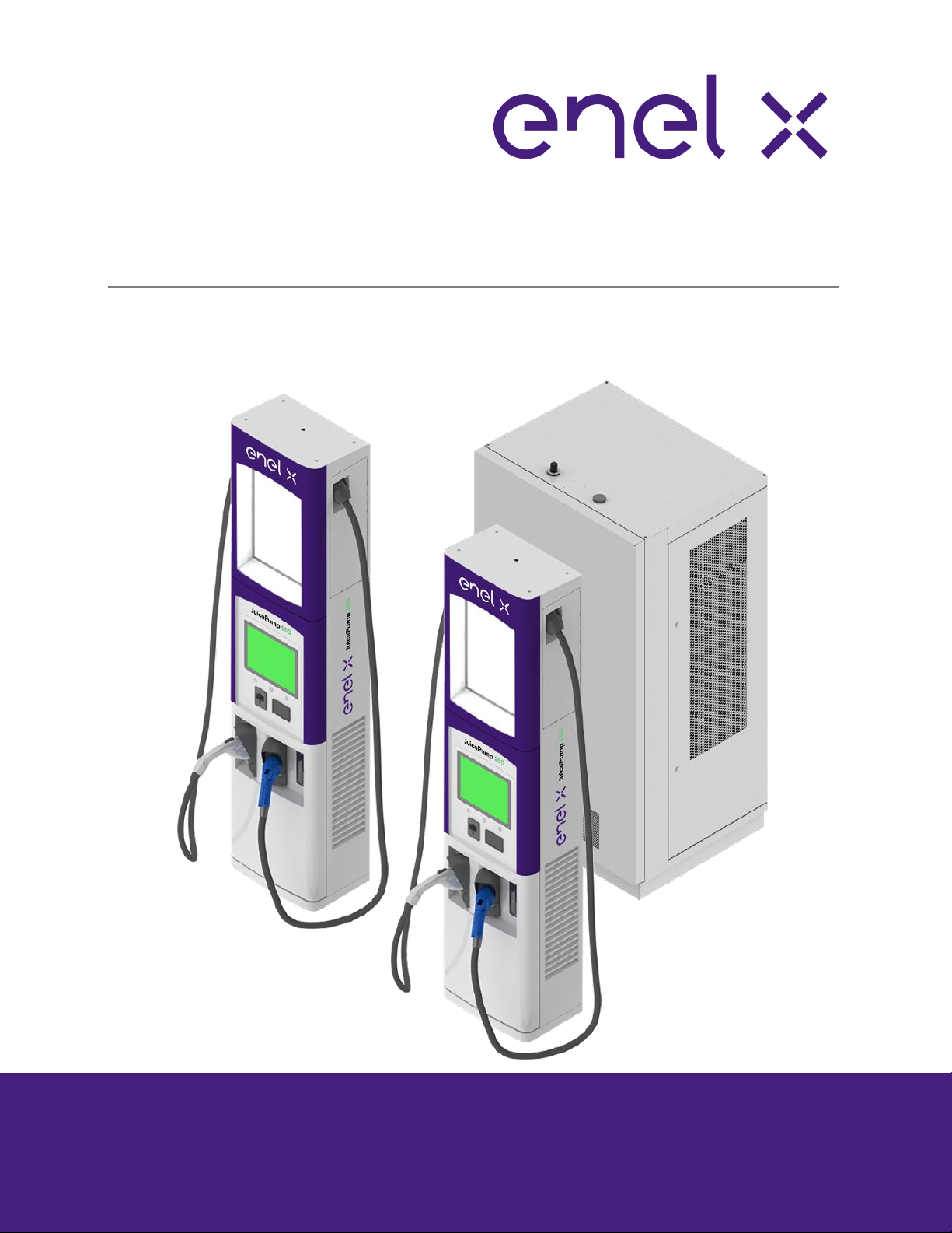
The JuicePump 150 converts a 480VAC 3-phase voltage into DC voltage to directly charge an
electric vehicle’s lithium-ion battery. It is capable to charge all electric vehicles compliant with
CHAdeMO charging system and Combined Charging System (CCS) standards.
The charger is composed of a 150kW Power Unit (with 3 individual 50kW power modules on it)
and one or two dispenser/s depending on the configuration. The dispensers can either be a Dual
CCS or CCS/CHAdeMO configuration and a 350A or 200A rated.
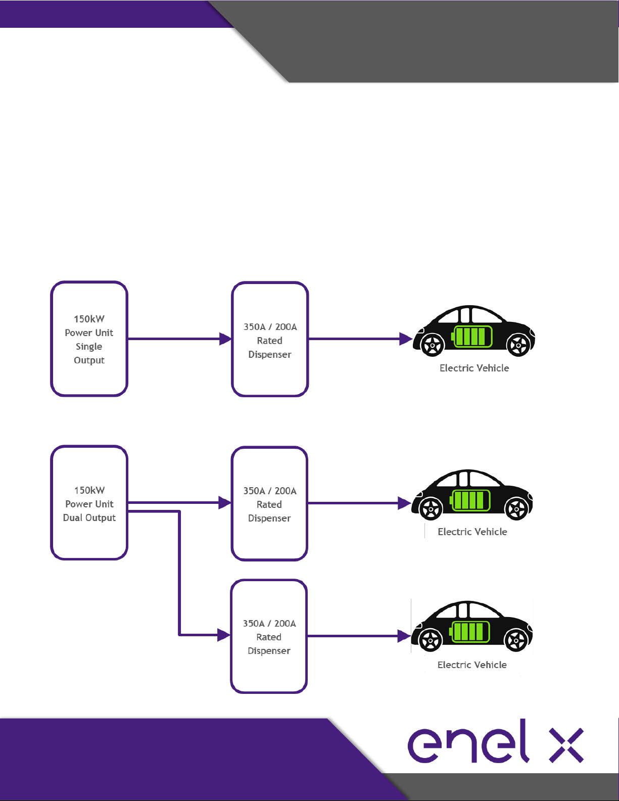
➢SIMPLIFIED BLOCK DIAGRAM (1-DISPENSER SYSTEM):
➢SIMPLIFIED BLOCK DIAGRAM (2-DISPENSER SYSTEM):

17-Jun-21
Initial Release
JuicePump 150
INSTALLATION AND USER’S MANUAL
Page 8of 68
EQUIPMENT DESCRIPTION
3. Equipment Description
150 kW HIGH POWER UNIT / TOWER
COMPONENT DESCRIPTION
1. 50KW #3 Power Module
2. 50KW #2 Power Module
3. 50KW #1 Power Module
4. Output Contactors (+/-) Power Module #3
5. Output Contactors (+/-) Power Module #2
6. Output Contactors (+/-) Power Module #1
7. Air Vent
8. Master Controller
9. Safety Relays
10. 24VDC Power Supplies
11. 12VDC Power Supply
12. Input Section
13. Output Section
14. Optical Transceivers
15. Empty slot for 50kW upgrade
* Power Module #4 as optional upgrade
17-Jun-21
Initial Release
JuicePump 150
INSTALLATION AND USER’S MANUAL
Page 9of 68
EQUIPMENT DESCRIPTION
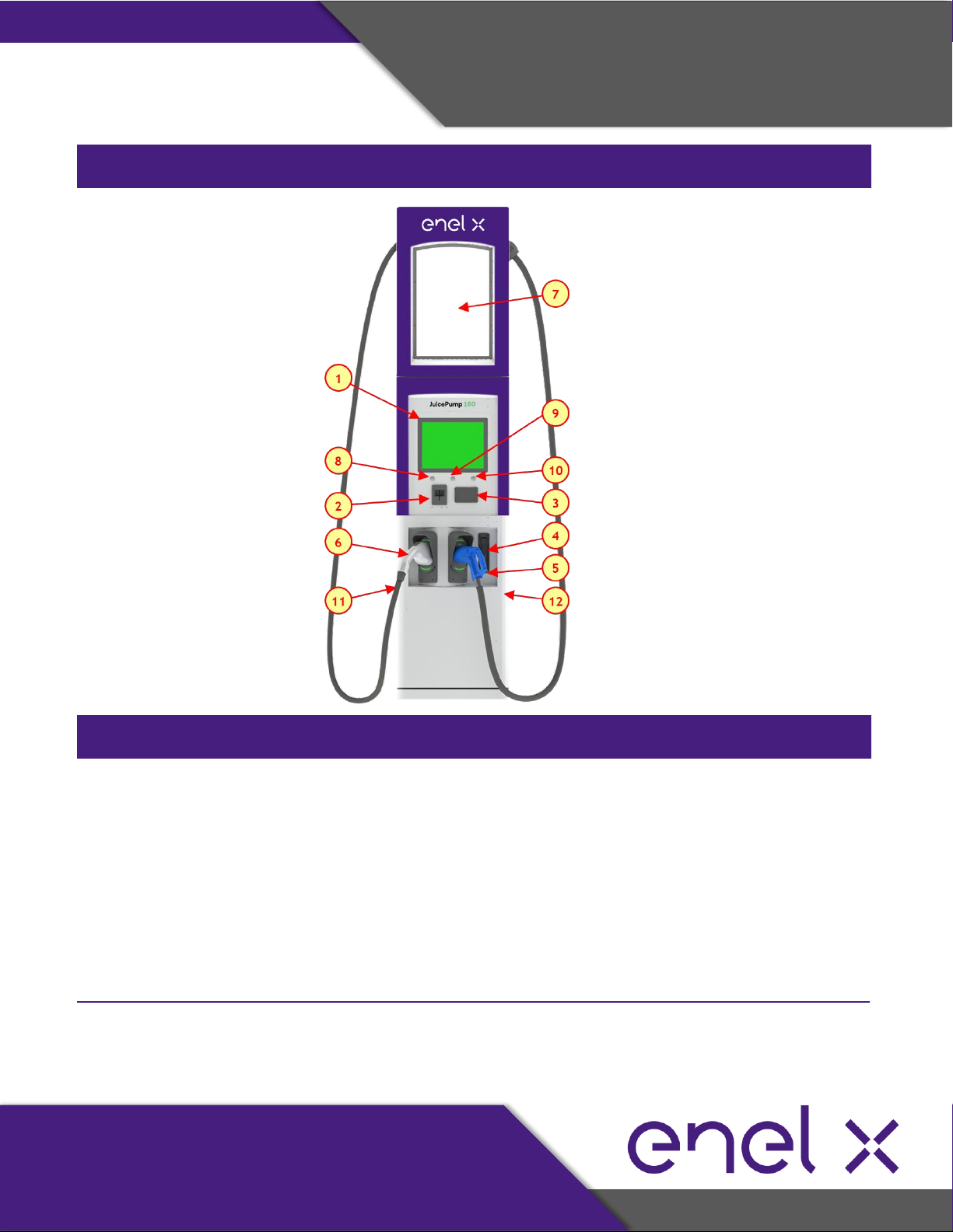
350A / 200A CHARGE DISPENSER
COMPONENT DESCRIPTION
1. 15-inch Outdoor-Rated Display and
Touch Screen
2. Magnetic stripe Credit Card Reader
3. RFID Card Reader
4. High Security Lock
5. Charging Connector 1
6. Charging Connector 2
7. Customer Advertising Panel
8. Start Button / Function Key 1
9. Stop Button / Function Key 2
10. Emergency Stop Button / Function Key 3
11. Air Inlet (left side)
12. Air Exit (right side)

17-Jun-21
Initial Release
JuicePump 150
INSTALLATION AND USER’S MANUAL
Page 10 of 68
EQUIPMENT DESCRIPTION
SYSTEM COMPONENTS
Power Unit / Tower
ITEM
DESCRIPTION
MODEL NUMBER
SKU
1
DCFC Power Unit Dual Output, SCCR 65kA
EVPC-150-2-480-3-65
HPCT-150-480-2
Dispenser
ITEM
DESCRIPTION
MODEL NUMBER
SKU
2
DCFC 350A Dispenser, CCS/CHAdeMO
EVDSP-350-5-120-0-2-C-4-0
HPCD1-350-01-003
3
DCFC 350A Dispenser, Dual CCS
EVDSP-350-4-120-0-2-C-4-0
HPCD1-350-02-003
4
DCFC 200A Dispenser, CCS/CHAdeMO
EVDSP-200-5-120-0-2-C-4-0
HPCD1-200-01-003
5
DCFC 200A Dispenser, Dual CCS
EVDSP-200-4-120-0-2-C-4-0
HPCD1-200-02-003

17-Jun-21
Initial Release
JuicePump 150
INSTALLATION AND USER’S MANUAL
Page 11 of 68
SYSTEM SPECIFICATION
4. System Specification
4.1. DCFC Power Unit
AC to DC Power Converter Specification
Model Number: EVPC-150-2-480-3-65
SKU: HPCT-150-480-2
PARAMETER
150kW POWER UNIT / TOWER
AC Input
Input Voltage Range
480 VAC, 3 Phase, +10% / -15%
Input Frequency Range
47 –63 Hz
Input Current @ 480 VAC
198 A
Power Factor
> 0.99 full load
Total Harmonic Distortion
< 5%
Efficiency
> 92%
SCCR
65 kA
Idle Power Consumption
159.5 W
DC Output
Output Voltage Range
50 –920 VDC
Maximum Output Current
CCS: 350 A, CHAdeMO: 200 A
Maximum Output Power
150 kW
Minimum Output Current
5 A
Output Ripple Current
< 15 Ap–p (Bandwidth 1 kHz)
Protection
Over Temperature
Self–protected and Latched
Output Over Voltage
Output Shutdown and Latched
Output Overload
Output Shutdown and Latched
CAN Communication Loss
1 sec Shutdown Upon Loss of Connection
Safety Standards
Isolation
UL 2231–1/2, UL 840
EMC Standards
Harmonics
IEC 61000-3-12
Immunity
UL 2231-2
Environment Conditions
Operating Temperature Range
-30°C to +50°C
Operating Altitude
6,000 ft.
Humidity
95% Non-Condensing
Mechanical Characteristics
Dimensions
42“ W x 35” D x 82“ H
Weight
1892 lbs
Enclosure IK Rating
IK 08
Enclosure IP Rating
IP 54 (NEMA 3R)
Specifications are subject to change without prior notice.

17-Jun-21
Initial Release
JuicePump 150
INSTALLATION AND USER’S MANUAL
Page 12 of 68
SYSTEM SPECIFICATION
4.2. DCFC Dispenser
High Power Dispenser Specification
Model Numbers: EVDSP-350-5-120-0-2-C-4-0, EVDSP-350-4-120-0-2-C-4-0
EVDSP-200-5-120-0-2-C-4-0, EVDSP-200-4-120-0-2-C-4-0
SKUs: HPCD1-350-01-003, HPCD1-350-02-003, HPCD1-200-01-003, HPCD1-200-02-003
PARAMETER
DISPENSER
350A Rated
200A Rated
AC Input
Auxiliary Input Voltage
120 VAC, Single phase, +/-10%
Auxiliary Input Current
21 A
10 A
Input Frequency Range
47 –63 Hz
Panel Breaker
30 A
Power Quality
IEEE-519 and IEC 6200-3-4
Idle Power Consumption
143.06 W
DC Input
Input Voltage Range
50 –920 VDC
Input Current Range
5 –500 A
DC Output
Dual CCS Configuration
Maximum DC Output Current
CCS, continuous
350 A
500 A
(boost mode; non-continuous)
200 A
CHAdeMO + CCS Configuration
Maximum DC Output Current
CHAdeMO, continuous
200 A
200 A
Maximum DC Output Current
CCS, continuous
350 A
200 A
Environment Conditions
Operating Temperature Range
-30°C to +50°C
Operating Altitude
6,000 ft.
Humidity
95% Non-Condensing
Mechanical Characteristics
Outdoor Enclosure
NEMA 3R, IP 54 equivalent
Dimensions
22“ W x 15” D x 97“ H
Weight
600 lbs
LED Lighting System
580 lumens

17-Jun-21
Initial Release
JuicePump 150
INSTALLATION AND USER’S MANUAL
Page 13 of 68
PRE-INSTALLATION
5. Pre-Installation
Prior performing any installation activities, it is important to go through each of the items
outlined in this section which are essential for the installation process.
5.1. Location Selection
Thing to consider when choosing a location to install the unit:
•Standards for Accessible Design (refer to section 5.3)
•Conformance to all governing standards for location and placement of the charger
•Communications Connectivity
oRefer to Enel X guidelines in “Determining Suitability of Site for Cellular Connectivity”
oEnsure that installation location meets the Cellular Signal Strength Criteria below
Parameter
Min Value
Device
Notes
RSSI
-69 dBm
SureCall
If RSSI < - 69dBm, measure RSRP,
RSRQ, and SNIR
RSRP
-100 dBm
Squid or -Cellular Meter
Please consult Enel X
Application Engineering
RSRQ
-11 dBm
Squid or -Cellular Meter
Please consult Enel X
Application Engineering
SNIR
> 6 dB
Squid or -Cellular Meter
For Reference
•Local Conditions
oArea is not expose to high temperatures, dust, corrosive fumes, combustible materials, or
explosive gases
oArea is dry and well-ventilated
oClearances at both sides for proper ventilation
oClearance at front and sides for accessibility during service (refer to Section 7.2.1)
oWiring and conduit needed to connect the charger to the circuit panel
oLocation of vehicle’s charging inlets while parked
oUse of protective bollards and wheel stops to protect the charger

17-Jun-21
Initial Release
JuicePump 150
INSTALLATION AND USER’S MANUAL
Page 14 of 68
PRE-INSTALLATION
5.2. Cable Reach
The cables of the dispenser come in different lengths depending on the dispenser configuration
and cable/connector type. The table below shows the connector type with its corresponding
cable reach while the figure shows the radius in which the two (2) DC connectors can be used.
Dispenser
Connector
Cable Reach
HPCD1-350-01-003
CCS1 (500A)
11.15 feet
CHAdeMO (200A)
10.5 feet
HPCD1-350-02-003
CCS1 (500A)
11.15 feet
CCS1 (500A)
11.15 feet
HPCD1-200-01-003
CCS1 (200A)
13 feet
CHAdeMO (200A)
10.5 feet
HPCD1-200-02-003
CCS1 (200A)
13 feet
CCS1 (200A)
13 feet

17-Jun-21
Initial Release
JuicePump 150
INSTALLATION AND USER’S MANUAL
Page 15 of 68
PRE-INSTALLATION
5.3. ADA Consideration
STANDARDS FOR ACCESSIBLE DESIGN for Americans with Disabilities is applicable when choosing
the location and placement of all Electric Vehicle Supply Equipment. The following is a direct
excerpt from the 2010 ADA Standards for Accessible Design:
http://www.ada.gov/2010ADAstandards_index.htm
“The Department of Justice published revised regulations for Titles II and III of the Americans with
Disabilities Act of 1990 “ADA” in the Federal Register on September 15, 2010. These regulations
adopted revised, enforceable accessibility standards called the 2010 ADA Standards for
Accessible Design “2010 Standards” or “Standards”. The 2010 Standards set minimum
requirements –both scoping and technical –for newly designed and constructed or altered State
and local government facilities, public accommodations, and commercial facilities to be readily
accessible to and usable by individuals with disabilities.
Adoption of the 2010 Standards also establishes a revised reference point for Title II entities that
choose to make structural changes to existing facilities to meet their program accessibility
requirements; and it establishes a similar reference for Title III entities undertaking readily
achievable barrier removal.
The Department has assembled this online version of the official 2010 Standards to increase its
ease of use. This version includes:
•2010 Standards for State and Local Government Facilities Title II
•2010 Standards for Public Accommodations and Commercial Facilities Title III
The Department has assembled into a separate publication the revised regulation guidance that
applies to the Standards. The Department included guidance in its revised ADA regulations
published on September 15, 2010. This guidance provides detailed information about the
Department’s adoption of the 2010 Standards including changes to the Standards, the reasoning
behind those changes, and responses to public comments received on these topics. The
document, Guidance on the 2010 ADA Standards for Accessible Design, can be downloaded
from:
http://www.ada.gov
17-Jun-21
Initial Release
JuicePump 150
INSTALLATION AND USER’S MANUAL
Page 16 of 68
PRE-INSTALLATION
For information about the ADA, including the revised 2010 ADA regulations, please visit the
Department’s website www.ADA.gov; or, for answers to specific questions, call the toll-free ADA
Information Line at 800- 514-0301 (Voice) or 800-514-0383 (TTY).”
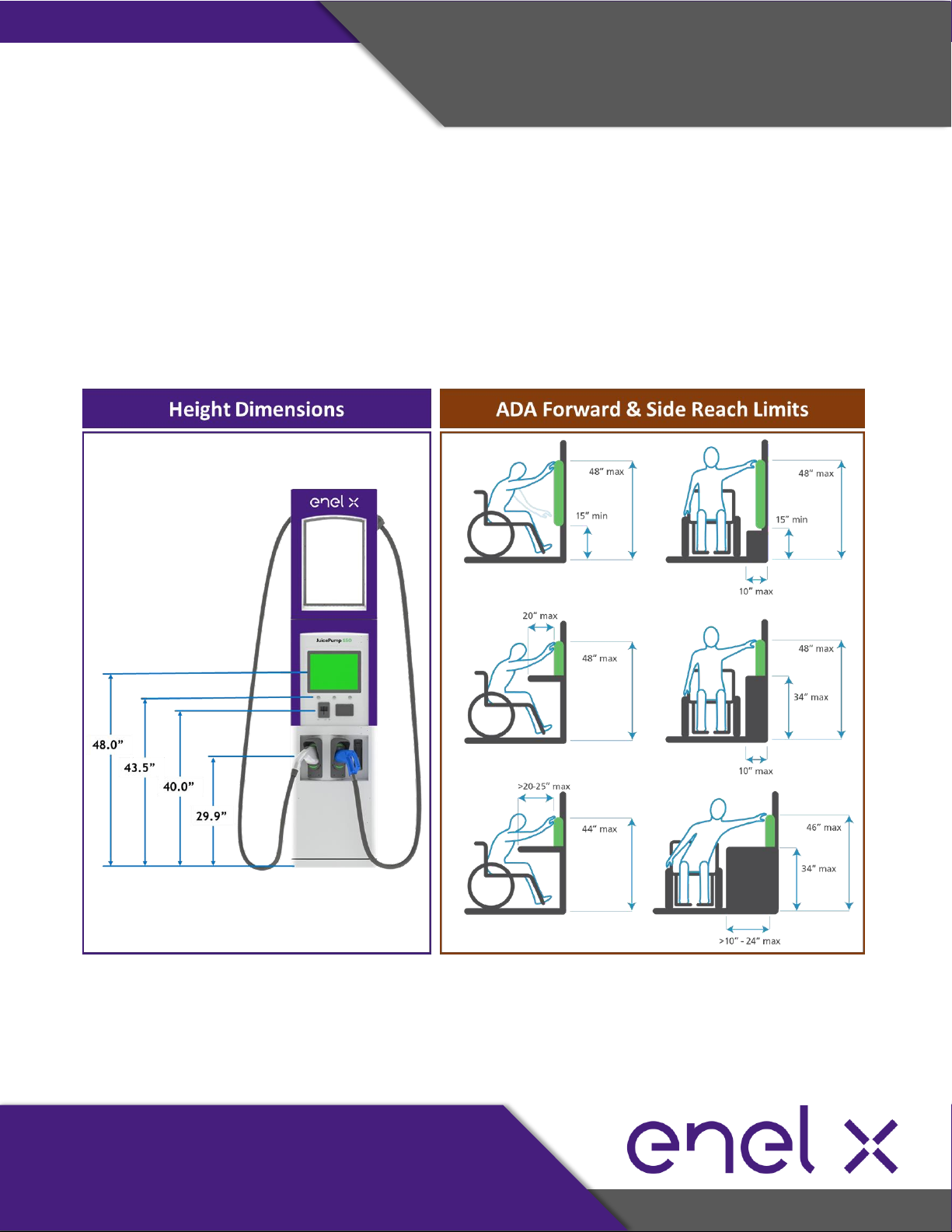
Compliance to ADA Standards
Access to all the controls and commands including the buttons and the card reader, must
comply with local codes and ADA requirements. That includes being under 48” of distance to
the ground.

17-Jun-21
Initial Release
JuicePump 150
INSTALLATION AND USER’S MANUAL
Page 17 of 68
PRE-INSTALLATION
5.4. List of Parts, Materials, and Tools Needed for Installation
Parts & Materials Needed to Purchase
Item
Part Description
Quantity
Remarks
1
OM3, multimode, 50/125µm,
ST connectors on both ends
2 pairs per
dispenser
Recommended supplier:
https://fibercablesdirect.com/
2
18AWG Twisted Pair, Shielded,
Interlock Cable
1
3
DC Wire
1 pair per
dispenser
4
AC 120VAC Wire
1 pair per
dispenser
5
Ethernet Cable
1 per dispenser
*Note: Extra sets of Fiber Optic Connectors are needed as back-up since these breaks easily.
Tools Needed during Installation
Item
Part Description
Quantity
1
Philips Head Screwdriver
1
2
½” x 4” Concrete Expansion Bolt
4
3
½” Torque Wrench
1
4
Allen Wrench Set
1
5
Keys (shipped with the unit)
1

17-Jun-21
Initial Release
JuicePump 150
INSTALLATION AND USER’S MANUAL
Page 18 of 68
TRANSPORTATION AND HANDLING
6. Transportation and Handling
6.1. Packaging
The power unit/tower and dispenser are packaged, shipped, and delivered in wood crates.
Below are the details of its packaging and dimensions for both tower and dispenser.
Item
Width (in)
Depth (in)
Height (in)
Weight (lb)
Power Unit/ Tower
49
42
90
up to 1998
Dispenser
37
30
103
up to 740
6.2. Transport, Handling, and Storage
Transport
The tower and dispenser must be transported upright or in vertical position. Liquid may leak or
other materials may get damaged if tilted or transported on its side.
Moving and Hoisting
Forklift or pallet truck can be used in moving or transporting the tower and dispenser. In addition
to this, the tower and dispenser can be moved or lifted using the lifting eye bolts.
Refer to section 7.1 for more details.

17-Jun-21
Initial Release
JuicePump 150
INSTALLATION AND USER’S MANUAL
Page 19 of 68
TRANSPORTATION AND HANDLING
Storage
The tower and dispenser must be stored in its original wood packaging in a dry environment from
-30°C to +50°C.
6.3. Receiving and Unpacking
Receiving Instructions
Once shipment is received, please follow these receiving instructions. It is the responsibility of the
receiver to perform visual inspection on the shipment and immediately notify Enel X Project
Manager for any damage.
•Unload and carefully inspect the crate or packaging for any damage caused by
mechanical impacts or any incidents during its transportation.
•Inspect the Tip N Tell tilt indicator attached on the crate. Tip N Tell tilt indicator provides
information of the shipment conditions during transit. Blue beads in arrow indicates crate has
been on its side or tipped over in transit.
•Note on the delivery receipt any visible damage to the crate/packaging or shipment has
been tipped based on the Tip N Tell tilt indicator. Provide information of the damage as
detailed as possible.
•For any issues or questions regarding the shipment, please call Enel X Shipment In-charge at
(714) 706 –4970.

17-Jun-21
Initial Release
JuicePump 150
INSTALLATION AND USER’S MANUAL
Page 20 of 68
INSTALLATION
7. Installation
SAFETY INSTRUCTIONS
The JuicePump 150 should be installed in accordance with local codes and all applicable
ordinances.
Read all installations instructions carefully prior to performing the installation.
DANGER
The equipment utilizes high voltages, only qualified electrical personnel familiar with the
operation and construction should install, adjust, modify, and service this equipment. Failure to
observe this precaution could result to severe injury or death.
WARNING
•The equipment may be installed outdoors but only use under environment conditions as stated
in this document.
•Do not perform any live wire operations.
•Do not touch the inside of the equipment while it is running.
•This equipment includes capacitive components such as electrolytic capacitors. Some parts
may still remain charged inside of the unit even after the input power is disconnected.
•This charger should not be modified in any way. This will void the warranty, compromise
protection and could result in a possible shock or fire hazard.
•Personal Protective Equipment should be used at all times when working with the equipment.
CAUTION
During installation of the unit, ensure that the charge station’s supply cable is in such a way that
it will not be tripped over, stepped on, pulled on, or somehow subjected to damage or stress.
This manual suits for next models
5
Table of contents
Other Enel X Batteries Charger manuals

Enel X
Enel X Way JuiceBox User manual

Enel X
Enel X Waypole User manual

Enel X
Enel X Way Next Gen JuiceBox User manual

Enel X
Enel X JuiceBox User manual

Enel X
Enel X JUICEBOX PRO User manual

Enel X
Enel X Waymedia 2 User manual

Enel X
Enel X JuicePump User manual

Enel X
Enel X Waybox Pro User guide

Enel X
Enel X JUICEBOX PRO User manual

Enel X
Enel X JUICEBOX PRO User guide


