Enel X JuicePump User manual

50kW DC
RT
www.enelx.com
Phone: +1-844-584-2329
Installation Manual
TRI93-50-01-UL


www.enelx.com
Phone: +1-844-584-2329
Important safety instructions and specications. Save these instructions.........................1
FCC Notice.............................................................................................................................3
Packaging, handling & receipt...............................................................................................4
Site conguration...................................................................................................................5
Underground power preparation...........................................................................................9
Above ground power preparation........................................................................................10
Installation requirements & equipment...............................................................................11
Unpacking & installation preparation...................................................................................13
Installation............................................................................................................................16
Underground conduit and wiring..........................................................................................18
Above ground conduit and wiring........................................................................................20
Wire & commission...............................................................................................................21
Ethernet port access............................................................................................................23
Closing checklist...................................................................................................................24
Installation checklist.............................................................................................................27
Contents

1www.enelx.com
Phone: +1-844-584-2329
Important safety instructions and
specications. Save these instructions
This manual contains important
instructions for the JuicePump electric
vehicle fast charger.
These instructions must be followed
during installation of the unit.
For charger operating instructions, see
JuicePump Operating Manual.
For charger maintenance instructions, see
JuicePump Maintenance Manual.
Identifying symbols
CAUTION
RISK OF ELECTRIC SHOCK
Equipment Grounding
Conductor Symbol
ø Phase Symbol
Alternating Current Supply
Symbol
CAUTION
The JuicePump fast charger must be
installed and serviced only by qualied
electrical personnel. To achieve EMC
compliance, the chassis of the JuicePump
must be bonded to Earth locally at the
charger.
CAUTION
In the event of a circuit breaker trip, the
charger must be inspected by an Enel
X-certied service agent before the char-
ger is re-energized.
Grounding instructions
This unit is to be connected to a
grounded, metal, permanent wiring
system; and an equipment-grounding
conductor is to be run with circuit
conductors and connected to
equipment-grounding terminal or lead on
battery charger. Connections to the bat-
tery charger shall comply with all local
codes and ordinances.
Observe all pertinent national,
regional and local safety laws and
regulations when installing and
commissioning the JuicePump fast char-
ger.
Wiring size
3ø: 4 AWG
Use 90°C Copper Wire
Use 4 AWG insulated
grounding conductor
1ø: 18 AWG
Use 90°C Copper Wire
An insulated grounding conductor that is
identical in size, insulation material and
thickness to the grounded and
ungrounded branch-circuit supply
conductors except that it is green with or
without one or more yellow stripes is to
be installed as part of the branch circuit
that supplies the unit or system. This
grounding conductor is to be grounded to
earth at the service equipment or, when
supplied by a separately derived system,
at the supply transformer.

2www.enelx.com
Phone: +1-844-584-2329
Input:
3ø WYE CONNECTED
277/480V ±10%
60Hz
55kW
1ø, 120V
60Hz
250W
The JuicePump must be connected to a
circuit provided with appropriate branch
circuit over-current protection in
accordance with the National
Electrical Code, ANSI/NFPA 70.
Tightening torque:
Wiring terminals:
Breaker 4.0 Nm/35 lb-in
Service hatch:
2.0 Nm/17.70 lb-in
Operating temperature:
-35° to 50°C / -31° to 122°F
Maximum ambient
temperature:
55°C /131°F
Weather rating:
NEMA Type 3R
Important safety instructions and
specications. Save these instructions

3www.enelx.com
Phone: +1-844-584-2329
FCC Notice
Information to the user
(FCC Part 15.105)
Class A product:
NOTE:
This equipment has been tested and
found to comply with the limits for a Class
A digital device, pursuant to part 15 of
the FCC rules. These limits are designed
to provide reasonable protection against
harmful interference when the equipment
is operated in a commercial environment.
This equipment generates, uses and
can radiate radio frequency energy and,
if not installed and used in accordance
with the instruction manual, may cause
harmful interference to radio communi-
cations. Operation of this equipment in a
residential area is likely to cause harmful
interference in which case the user will be
required to correct the interference at his
own expense.
Modication warning
(FCC Part 15.21)
In addition the user’s manual or
instruction manual shall caution the
user that changes or modications
not expressly approved by the party
responsible for compliance could void
the user’s authority to operate the
equipment (see below for example)
Warning: Any changes or
modications not expressively
approved by (Enel X) could void
the user’s authority to operate this
equipment

4www.enelx.com
Phone: +1-844-584-2329
Read these instructions carefully to
become familiar with JuicePump packag-
ing and handling procedures prior to
unpacking and installation.
In all cases, the JuicePump is to be
transported to the installation site in its
original packaging and only unpacked at
the installation site.
Installation, commissioning and servicing
of the JuicePump should only be carried
out by qualied personnel.
Materials:
The JuicePump is transported in a
reinforced cardboard crate.
Please respect the environment and
recycle/reuse the materials.
Storage:
Store in the original packaging in a
horizontal position.
Storage temperature:
-20 to 45°C / -4 to 113°F.
Handling:
Only lift the JuicePump packaging in its
horizontal orientation using a forklift,
pallet jack or with lifting straps and
engine hoist, forklift or crane. Check the
weight on the delivery documents and
ensure the lifting apparatus used is
compatible.
Receipt:
Check that the crate packaging is in
good condition and that the JuicePump is
not damaged.
If there are any problems noted, make a
formal complaint to the carrier and notify
your supplier.
Packed crate weight:
200kg/440lb
Crate size:
850(W) x 2150(H) x 450(D)mm
33.5(W) x 84.5(H) x 18(D) inches
JuicePump size:
750(W) x 2000(H) x 330(D)mm
29.5(W) x 78.7(H) x 13(D) inches
(without plugs)
JuicePump weight:
165kg/364lbs
Packaging, handling & receipt

5www.enelx.com
Phone: +1-844-584-2329
Site survey:
The JuicePump can be installed onto a
newly prepared concrete pad, or onto an
existing concrete surface, with service
wiring supplied through conduit via the
foundation or above ground.
A qualied engineer must
survey the installation site to determine
the correct ground preparation for the
size and weight of the JuicePump, in
accordance with all local applicable codes
and regulations.
If a foundation to supply power from
underground is to be prepared, follow the
underground power instruction for
installation.
If the charger is to be installed onto an
existing concrete surface, follow the
above ground power instruction for
installation.
The JuicePump is best installed following
the recommended site conguration
requirements.
Ground xing:
The JuicePump is to be xed to the
ground through the baseplate xing holes
with 4 x M16 or 5/8-11 inch fasteners
(not supplied). The fasteners should
x the Veel securely to the foundation
through the baseplate and protrude
30-40mm/1.2-1.6 inch maximum from
the foundation surface, in accordance
with the dimensions and xing points
shown in: Figure 5: Fixing guide.
See Figure 1: Dimensions walls or
obstacles, for installation against or near
walls or other obstacles.
Foundation requirements:
The foundation must be at, even, and
the appropriate density for the weight of
the JuicePump.
Check the atness and level of the
foundation and level of the JuicePump
baseplate prior to xing.
Communications:
4G network capability or Ethernet.
The JuicePump is tted with a Harting
external IP65 rated ethernet port. This
port can be accessed temporarily during
installation. If a more permanent, sealed
connection is required, use Harting
external ethernet connector, 9153000401.
See page 23 for ethernet port access.
Site restriction:
Installation shall not be done in a
commercial garage (repair facility) or
closer than 6 meters/20ft of an outdoor
motor fuel dispensing device.
Site conguration
6www.enelx.com
Phone: +1-844-584-2329
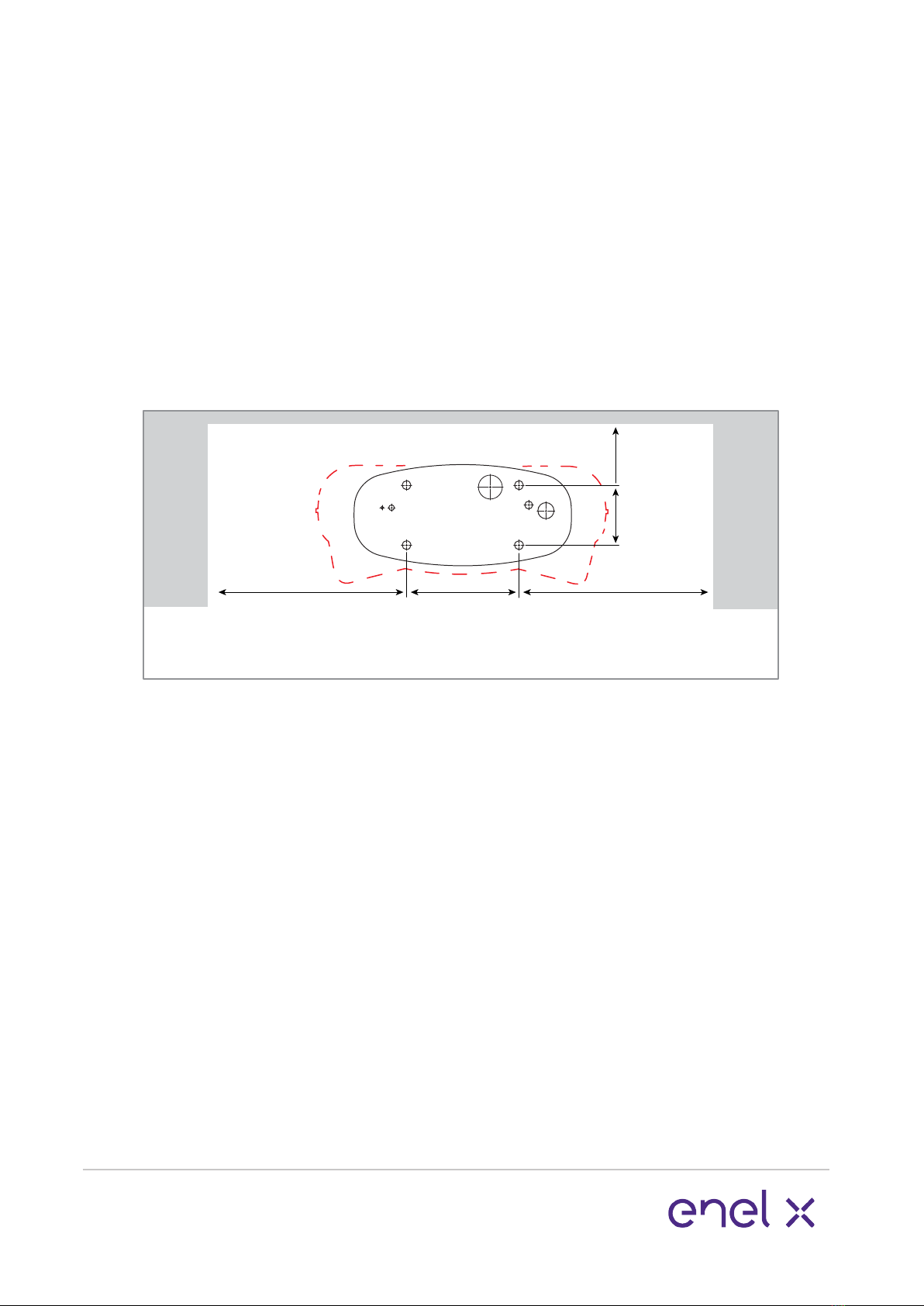
Site conguration
Minimum measurement
requirements:
Contact your Enel X representative for
installation advice if your mimimum
measurements are smaller than shown in
Figure 1.
28.5” (725)
minimum
6.3”
160
9.8”
(250)
11.8”
(300)
Do not scale
Wall Wall
Figure 1.
Dimensions walls or obstacles
28.5” (725)
minimum
7www.enelx.com
Phone: +1-844-584-2329
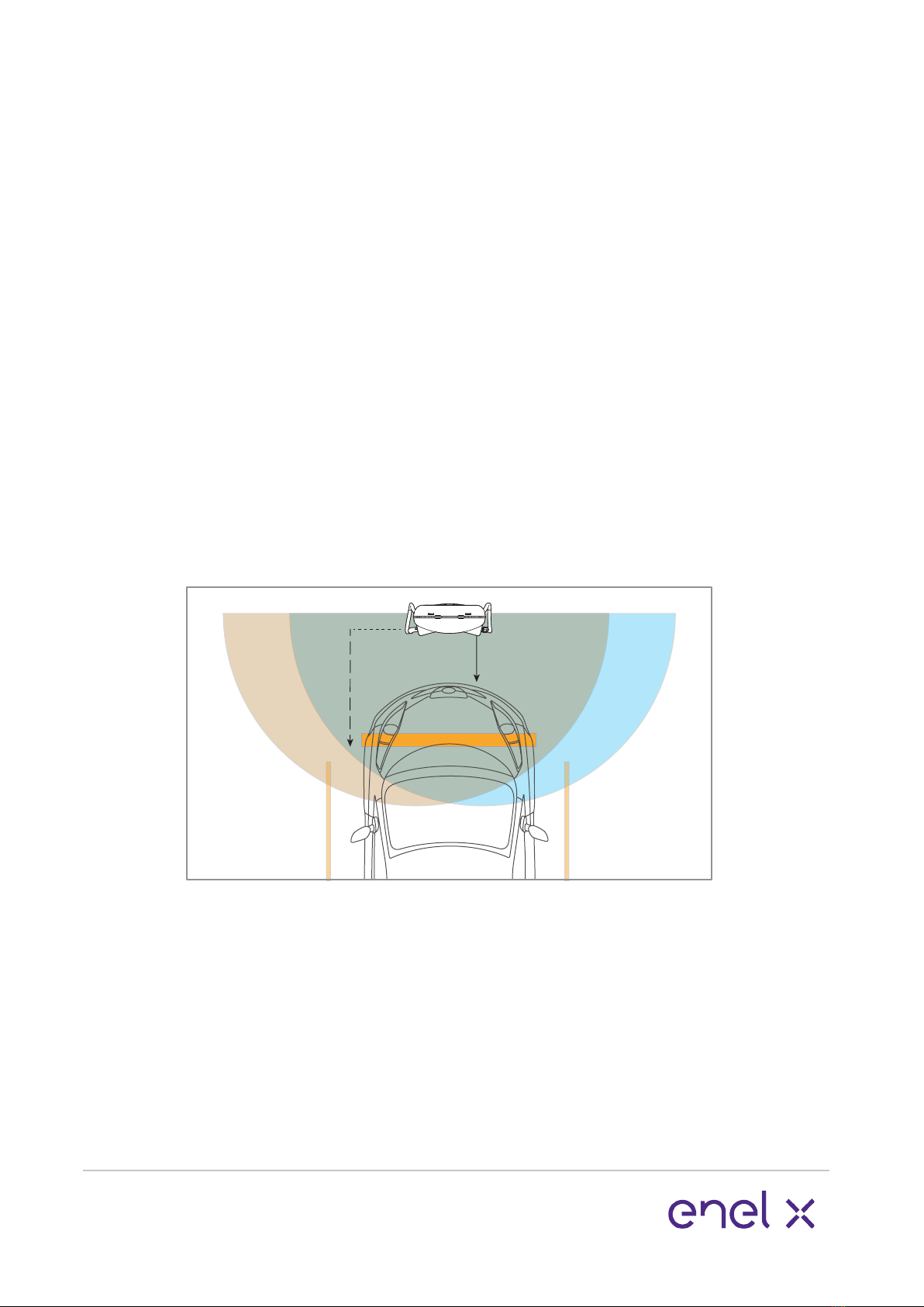
JuicePump charging cable range:
The standard JuicePump cable reach is
approximately 2.0 metres/6.5 feet as
shown in these site layouts.
Customised lengths are also available.
Contact your supplier should your
requirements dier.
If longer length cables are used please
ensure the cable is kept tidy and close
to the JuicePump sides at all times.
Single carparking bay:
To service one car bay, 500mm/20 inches
of space is recommended between the
car and the JuicePump front and back for
ease of use.
Wheel stops installed at 1200mm/4 feet
from the centre front of the JuicePump
can achieve this.
If the JuicePump is to be installed with it’s
back or sides against or near a wall or
other obstacle, use the minimum
distances shown in Figure 1.
Top view
Do not scale
20”
(500)
SAE Combo
Plug Range
CHAdeMO
Plug Range
47”
(1200)
WHEEL
STOPS
Figure 2.
Site conguration
8www.enelx.com
Phone: +1-844-584-2329
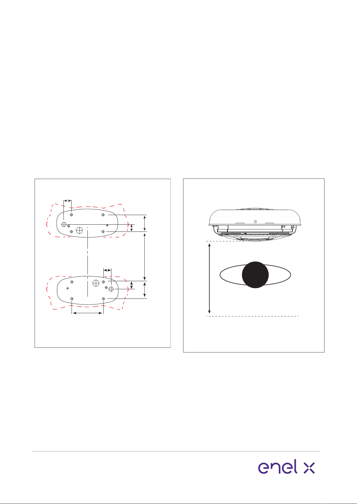
Site conguration back to back
units:
When being installed back to back, a
minimum distance of 300mm/12 inches
between the JuicePump chargers is
recommended.
To ensure this minimum distance is
observed use the dimensions for
foundation positioning in Figure 3.
30.3”
(72)
2.7”
(68)
6.3”
(160)
16”
(410)
11.8”
300
Figure 3. Back to back units
Do not scale
6.3”
(160)
30.3”
(72)
2.7”
(68)
Site conguration servicing:
A additional space of 700mm/27.5 inches
from the center front of the baseplate is
required to open the front panel for
servicing, as shown in Figure 4.
Do not scale
27.5”
(700)
Figure 4. Servicing distance
requirement
Site conguration
9www.enelx.com
Phone: +1-844-584-2329
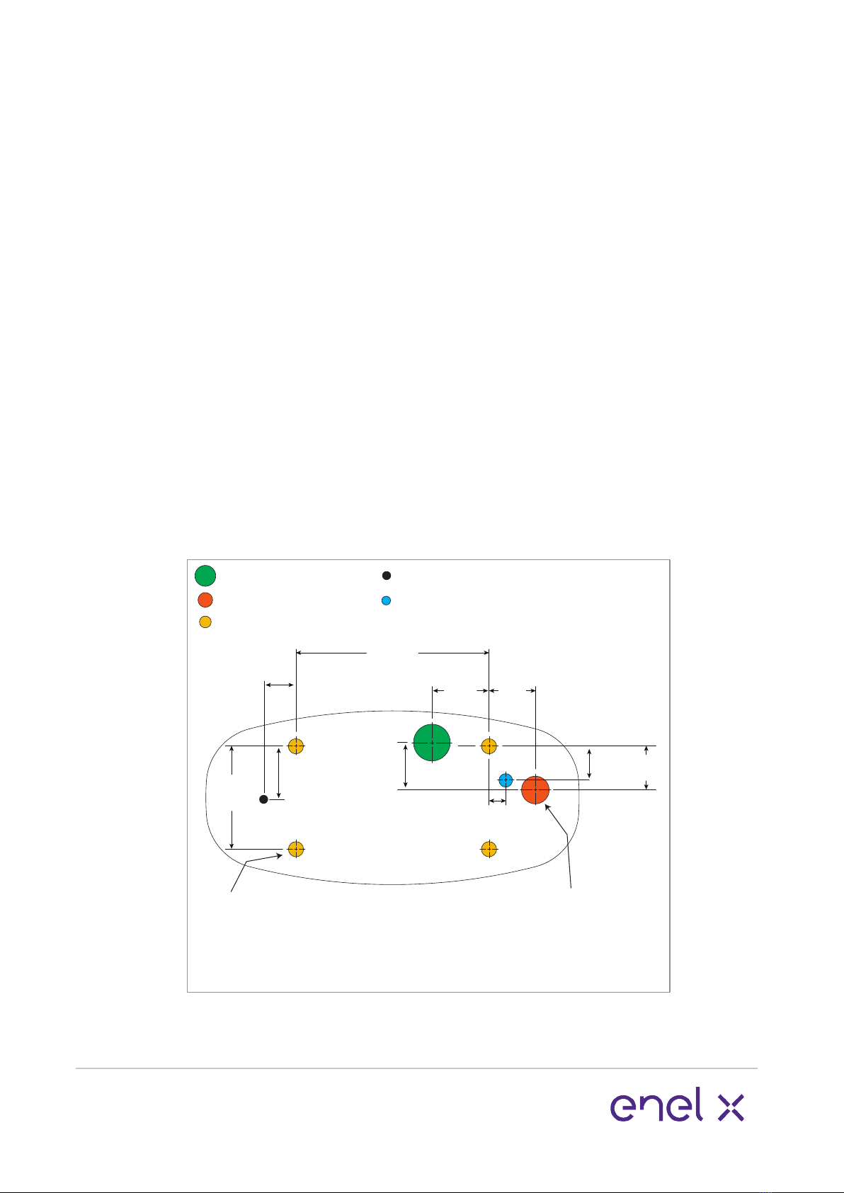
If a concrete foundation is being pre-
pared to bring power into the JuicePump
through the baseplate, use the following
as a guide for preparation.
Use the JuicePump template (supplied in
the crate kit) or measure as per Figure 5,
to ensure the xing points are correct.
Locate mounting studs and conduit within
0.05” (1.25mm) tolerance.
Foundation power hole:
When preparing the concrete foundation
a 1-1/4” NPT female coupling (not
supplied) is to be inserted ush with the
top surface of the concrete pad and
precisely located in the 50mm power hole
location in relation to the mounting studs.
This ensures the sealing of the supplied
exa conduit system into the foundation.
Fixing points:
Use 4x 5/8-11 studs, protruding 1.2-1.6
inches above the surface. If the studs
protrude more than this it will be
impossible to remove and replace the
radiator if required.
Ethernet cable hole:
If hardwiring in the ethernet, use this
hole for the cabling.
Underground power preparation
50mm power hole
Fixing point holes
Ethernet cable hole
Figure 5. Mounting reference.
6.3”
(160)
JUICEPUMP FRONT
11.8”
(300)
2.8”
(72)
2.7”
(68)
1.0”
(26)
2.1”
(53)
1-1/4” NPT
Female coupling
top to be flush
w/surface
Do not scale
4x 5/8-11 studs
Protruding 1.4”
±0.2” above
the surface
3.4”
(86)
2.5”
(63)
70mm power hole
2.3”
(60)
1.6”
(40)
Grounding rod hole

10 www.enelx.com
Phone: +1-844-584-2329
Figure 7. Top view
1 metre/3 feet
Not to scale
Back
left
fixing
point
Fixing points.
Use 4x 5/8-11 studs, protruding 1.2-1.6
inches above the surface. If the studs
protrude more than this it will be
impossible to remove and replace the
radiator if required.
Ethernet cable hole:
If hardwiring in the ethernet, use the hole
referenced in Figure 5.
If power via conduit is being supplied to
the JuicePump above ground, the conduit
will enter the JuicePump via the back
radiator panel on the left hand side as
shown in Figure 6.
Use the JuicePump template (supplied in
the crate kit) or or measure as per Figure
5, to ensure the xing points are correct.
Locate mounting studs and conduit within
0.05” (1.25mm) tolerance.
To ensure the correct seal is
maintained into the JuicePump, only use
Flexa 1-1/4 inch ROHRex conduit,
order code 0237.202.036 (not sup-
plied) to bring power cabling into the
JuicePump.
Figure 6.
Leave at least 1 metre/3 feet of power
cabling from the back left xing point, for
installation as shown in Figure 7.
Prior to installation the conduit and wiring
will require trimming.
Above ground power preparation

11 www.enelx.com
Phone: +1-844-584-2329
Installation requirements & equipment
These instructions provide a systematic
guide for installing and commissioning
the JuicePump.
The JuicePump must be installed and
serviced by qualied electrical personnel.
Observe all pertinent national, regional,
and local safety regulations when you
install and commission the JuicePump.
The JuicePump has a NEMA Type 3R
electronics enclosure rating, however, as
it must be opened for installation, this is
best done in dry weather or under
cover to avoid moisture or debris ingress.
Installation shall not be done in a
commercial garage (repair facility) or
closer than 6 meters/20ft of an outdoor
motor fuel dispensing device.
The JuicePump must be properly in-
stalled, assembled and commissioned
according to these instructions before it is
used.
Prior to installation contact your supplier
to organise commissioning information.
Supplied with JuicePump:
5mm pin hex tool to remove the M8
security screws xing the plastic panels.
2.5mm hex ‘L’ wrench
Lifting straps
Blanking plugs are tted for transport and
storage.
Flexa conduit system
Black ferrite ring ID13x40mm
Black ferrite ring ID25x43mm
Grey ferrite ring
Baseplate template
The JuicePump is shipped with a tem-
porary single phase power cable which
allows the unit to be powered prior to
installation.
This allows for software updates,
charger conguration and/or 4G
connectivity testing. The cable has a male
IEC socket and an IEC female lead is
required to supply power.
If pre installation power up is required
contact your supplier prior to the
installation date to synchronize with
Enel X.

12 www.enelx.com
Phone: +1-844-584-2329
Required equipment:
Lifting apparatus. See pg 4 for weights.
Ensure lifting apparatus is suciently
rated.
For height restricted areas alternative
lifting methods are available. Contact
your supplier for more information.
4x M16 or 5/8 glavanised or SS washers
4x M16 or 5/8-11 galvanised nuts to
match fasteners.
Flexa PN 0237.202.036 conduit (above
ground power installations only).
Tools:
Socket set & ratchet or adjustable
spanner.
Allen keys or socket set hex bits.
Power driver
Sockets required:
8mm for radiator removal and service
hatch removal.
10mm socket for earthing strap removal.
16mm for removal of shipping baseplate
bolts.
Approved external sealant.
DOCUMENT KEY:
Items shown in orange are parts that
require action for that step.
Installation requirements & equipment
13 www.enelx.com
Phone: +1-844-584-2329
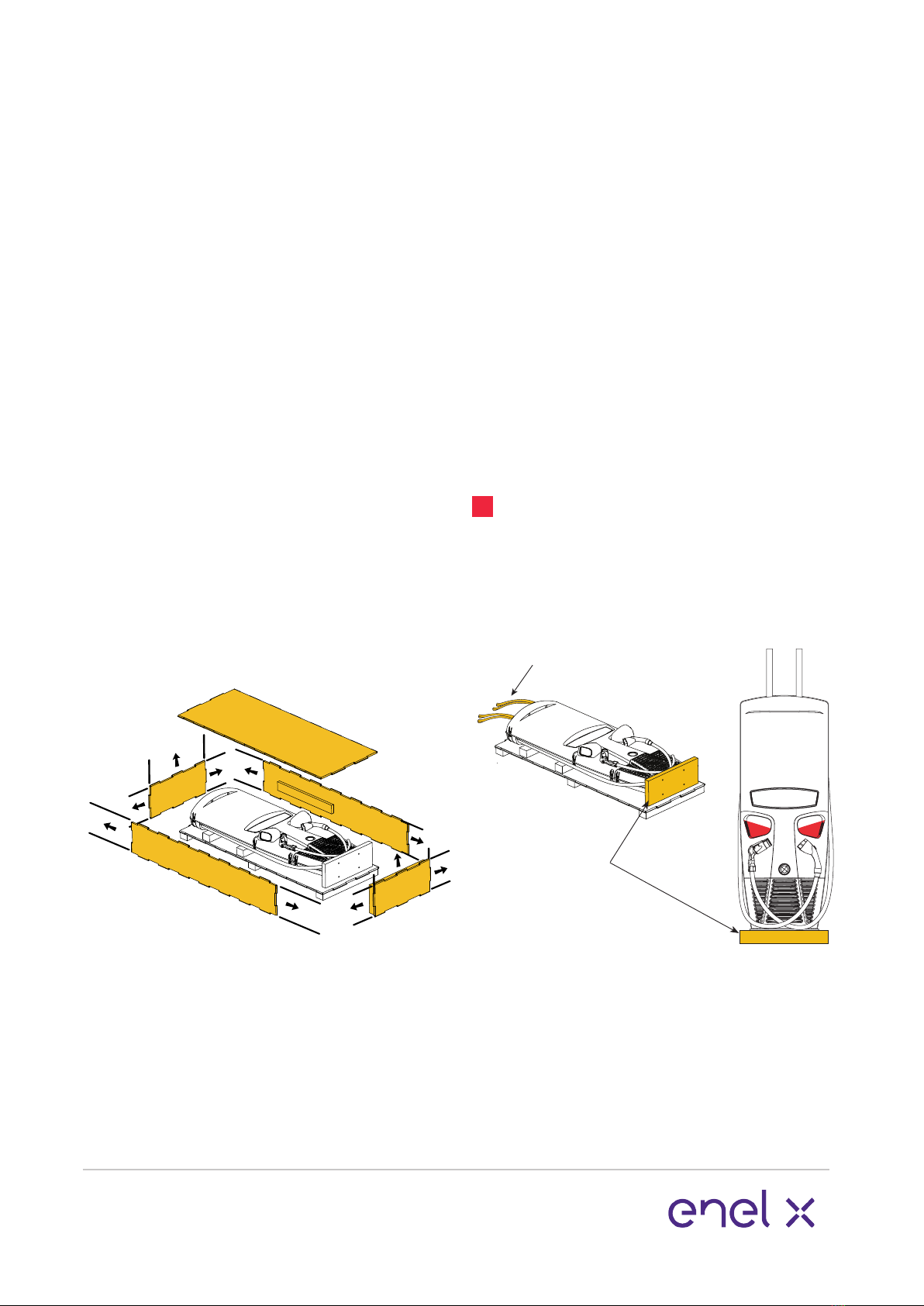
1. Open crate
Move the crate as close to the
prepared installation site as possible.
Ensure there is enough room to
manoeuvre the lifting apparatus.
Remove/slide out all crate tubes to
disassemble the cardboard crate.
2. Lift Veel-RT to vertical
Securely attach the lifting straps at the
top of the JuicePump to the lifting appa-
ratus and gently raise to a standing posi-
tion on the shipping baseplate.
The JuicePump must remain attached to
the lifting equipment until the mounting
bolts have been installed.
NOTE: The JuicePump is 2050mm/6.72ft
tall on the shipping baseplate.
Do not use the plug holders to assist
lifting the charger at any stage.
Once upright remove all wrapping.
Lifting Straps
Shipping
Baseplate
Unpacking & installation preparation

14 www.enelx.com
Phone: +1-844-584-2329
Removing the radiator from the base of
the JuicePump gives more space for
bringing power into the unit, however,
removing the radiator is not always
required. Assess the situation on site.
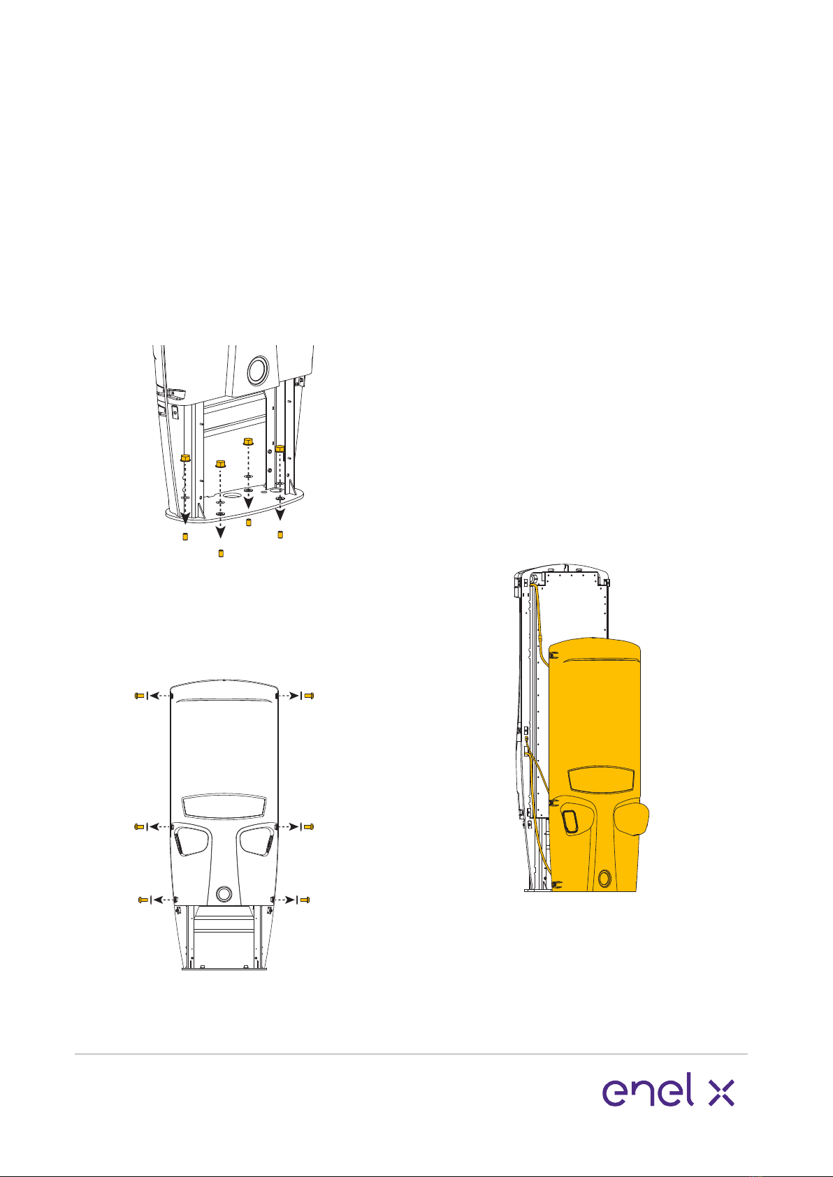
5. Remove radiator (optional)
Unscrew the 4x nuts using an 8mm nut
driver to remove the radiator. Pull the
radiator o the fasteners, and sit the
radiator on the base plate.
Reach behind and unclip the four way
connector.
The four way connector is the left hand
plug attached to the underside of the
unit. Squeeze front clip and pull down to
release.
3. Remove front and rear radiator
panels
If access to the rear radiator panel is
dicult, the internal radiator may be
removed to access the rear base xing
points. If so, remove the front radiator
panel only, and go to item 5.
Unscrew the 8x security screws and
remove them and the washers from both
radiator panels using the 5mm pin hex
tool. Pull the radiator panels away from
the metalwork frame to remove.
4. Remove shipping bolts
Unscrew the 4x bolts from the shipping
base to disengage. 16mm socket
required.
Note: Keep the plastic inserts from the
bolts for later use.
Unpacking & installation preparation
15 www.enelx.com
Phone: +1-844-584-2329
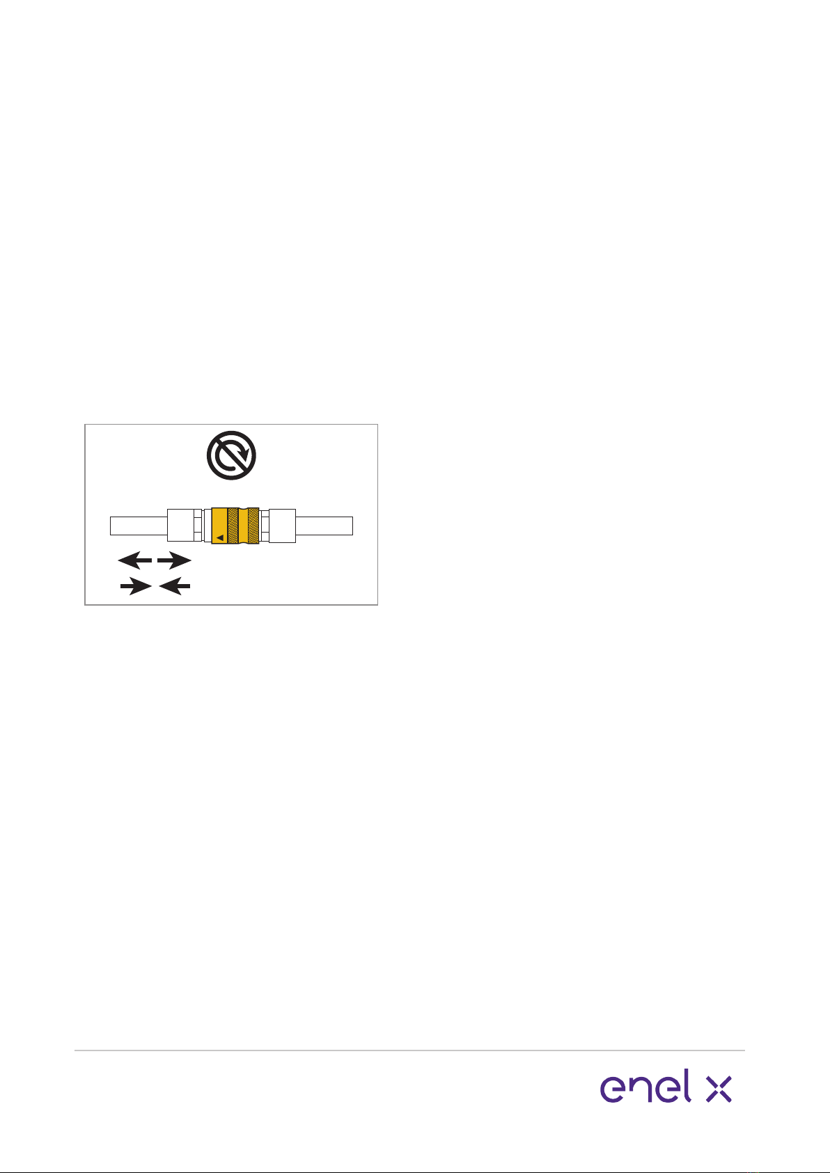
The radiator cooling system must be
disengaged from the unit. Unclip the two
quick release parts. One is on the base
behind the radiator, the other is on the
left side with the expansion bag.
NOTE: Do not twist or pull on the
tubing engaged with the metal quick
release parts. Pull on the metal parts to
release, and press the metal parts
together to join.
PULL
DO NOT TWIST
PULL TO RELEASE
PRESS TOGETHER TO JOIN
Store the radiator in a safe place ensuring
no damage to cooling hoses for later
re-assembly.
For the purpose of this manual, the
following installation pictures are shown
without the radiator.
Unpacking & installation preparation
16 www.enelx.com
Phone: +1-844-584-2329
Installation
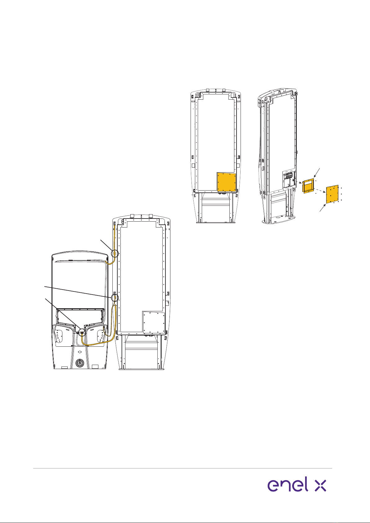
3. Place front panel on ground
The front panel is attached to the
enclosure with wiring and an earthing
strap on the front left hand side.
Lift the front panel up to release from the
top hook and gently lower to the ground
in front of the JuicePump.
In calm conditions it may be possible to
keep the front panel connected during
commissioning. If this is possible, go to
page 17, item 5.
If in doubt, disconnect the front panel
(see pg 17, item 4) and store in a safe
place until the unit is ready to close for
use.
1. Secure to foundation
Lift the JuicePump by the supplied lifting
straps, place onto the prepared
foundation and secure with the specied
fasteners.
Note: Use the plastic inserts you kept
earlier in the baseplate holes.
2. Remove fasteners from front panel
Remove the 6x security screws and
washers from the front panel using the
provided 5mm pin hex tool.
17 www.enelx.com
Phone: +1-844-584-2329
EXPLODED VIEW
Service
Cover
Service
Hatch
FRONT VIEW
The Service Hatch has an attached
gasket. Ensure this is carefully stored to
avoid damage or accumulation of debris.
6. Pre-installation power up
The JuicePump is shipped with a tem-
porary single phase power cable which
allows the unit to be powered prior to
installation. This is attached to the M40
blanking plug. This allows for software
updates, charger conguration and/or 4G
connectivity testing.
The cable has a male IEC socket and an
IEC female lead is required to supply
power.
If pre installation power up is required
contact your supplier to synchronize with
Enel X.
7. Remove IEC cable wiring
Remove the M40 blanking plug and IEC
cable wiring from the switch gear.
4. Disconnect front panel
There are three points to disconnect:
1. Wiring to the top rear panel.
Squeeze the connector to disconnect.
2. Earthing strap.
Unscrew the nut on the metalwork with
a 10mm socket. Remove the nut and
earthing strap lug from the stud.
3. Connector ‘B’ on the HMI panel.
Connector ‘B’ detaches by squeezing the
connector front and rear with your ngers
and pulling down.
1
2
3
5. Remove service covers
Remove the service hatch and cover to
access the internal enclosure to prepare
the JuicePump for wiring. Use an 8mm
socket and 2.5mm hex bits.
Installation
Other manuals for JuicePump
4
Table of contents
Other Enel X Batteries Charger manuals

Enel X
Enel X Waypole User manual

Enel X
Enel X Waypole User manual

Enel X
Enel X JUICEBOX PRO User manual

Enel X
Enel X Way Next Gen JuiceBox User manual

Enel X
Enel X JuicePump 150 User manual

Enel X
Enel X JuiceBox User manual

Enel X
Enel X Way JuiceBox OpenPay User manual

Enel X
Enel X JUICEBOX PRO User manual

Enel X
Enel X Waybox Pro User guide

Enel X
Enel X Way JuiceBox User manual


