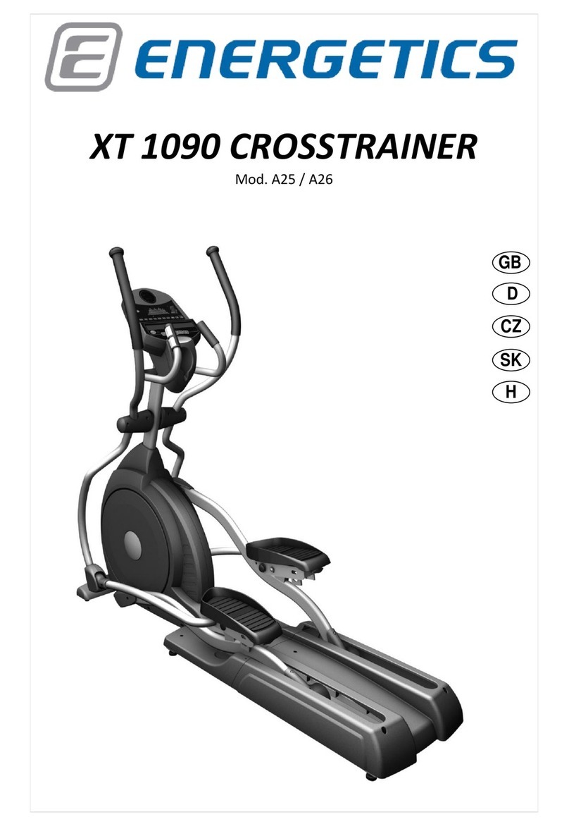
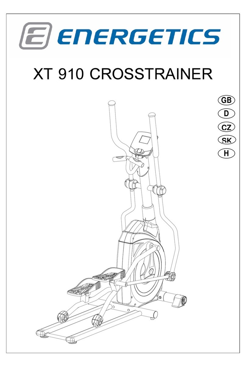
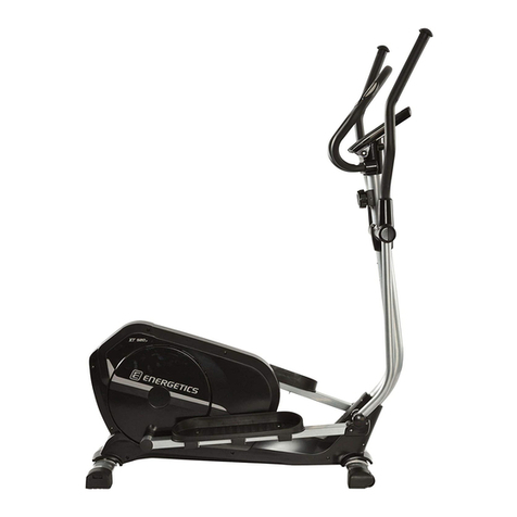
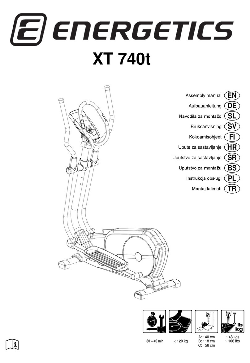
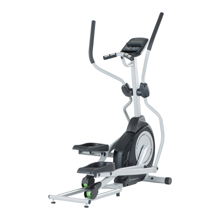
Energetics XT 1010 User manual

XT 1010 CROSSTRAINER
GB
D
CZ
SK
H

2
Table of contents - Inhaltsverzeichnis - Obsah - Obsah - Tájékoztató
English
P
3
Deutsch
P
27
Česky
P
52
Slovensky
P
76
Magyar
P
100
© The owner’s manual is only for the customer reference. ENERGETICS can not guarantee for mistakes occurring due to translation or
change in technical specification of the product.
©Die Gebrauchsanweisung dient nur zur Referenz für den Kunden. ENERGETICS übernimmt keine Haftung für Fehler die durch
Übersetzung oder technische Änderungen des Produkts entstehen.
©Návod k použití je pouze doporučení pro zákazníky. ENERGETICS nepřebírá žádné ručení za chyby způsobené překladem či změnami v
technické specfikaci výrobku.
© Tento návod je určený len pre potrebu zákazníkov. ENERGETICS nezodpovedá za chyby, ktoré sa môžu vyskytnúť kvôli
chybnému prekladu alebo zmenám v technickej špecifikácii produktu.
© A használati útmutató kizárólag felhasználói referenciaként szolgál. az ENERGETICS nem vállal felelősséget a fordítási
hibákból vagy a termék műszaki módosításaiból eredő hibákért.
© Copyright by ENERGETICS

3
Dear Customer,
Congratulations on your purchase of an ENERGETICS home exerciser. This product has been designed
and manufactured to meet the needs and requirements of in-home use. Please carefully read the
instructions prior to assembly and first use. Be sure to keep the instructions for reference and/ or
maintenance. If you have any further questions, please contact us. We wish you lots of success and
fun while training,
Your - Team
Warranty
ENERGETICS offers high quality home exercisers that have been tested and certified according to
European Norm EN 957.
ENERGETICS warrants to the original purchaser 2 years against possible defects in material and
workmanship. Excluded are damages caused by misuse and wearing parts. All electronic parts are
warranted for a period of 1 year. The warranty period starts at the date the product was purchased
(retain your sales receipt).
Safety Instructions
Consult your physician before starting with any exercise program to receive advice on the
optimal training.
Warning: incorrect/ excessive training can cause health injuries. Stop using the home
exerciser when feeling uncomfortable.
Ensure that training only starts after correct assembly, adjustment and inspection of the
home exerciser.
Always start with a warm-up session.
Only use original ENERGETICS parts as delivered (see checklist).
Follow the steps of the assembly instruction carefully.
Only use suitable tools for assembly and ask for assistance if necessary.
Place the home exerciser on an even, non-slippery surface.
For all adjustable parts be aware of the maximum position to which they can be adjusted.
Tighten all adjustable parts to prevent sudden movement while training.
This product is designed for adults. Please ensure that children only use it under the
supervision of an adult.
Ensure that those present are aware of possible hazards, e.g. movable parts during training.
The resistance level can be adjusted to your personal preference.
Do not use the home exerciser without shoes or loose shoes.
Ensure that sufficient space is available to use the home exerciser.
Be aware of non-fixed or moving parts whilst mounting or dismounting the home exerciser.
GB

4
To protect the floor or carpet from damage, place a mat under the Elliptical Trainer.
Turn off the power whilst the Elliptical Trainer is not in use.
Ensure that an area of 2000 x 1000 mm behind the Elliptical Trainer is free from any
obstacles.
This product is made for home use only and tested up to a maximum body weight of 120
kilograms.
We take no responsibility for personal injury or damage sustained by or through the use of
this home exerciser.
Handling
A. After assembly, the rear stabilizer can be adjusted to accommodate slightly uneven ground.
Turn the adjustment knobs on the ends of the rear foot caps to level the rear stabilizer to the
floor.
B. The transportation wheels on the front foot caps allow for easy manoeuvring. Simply pull
back on the handlebars until the wheels touch the floor. Then roll the unit to a desired
location.
Care and Maintenance
-The home exerciser should not be used or stored in a moist area because of possible
corrosion.
-Check at least every 4 weeks that all connecting elements are tightly fitted and in good
condition.
-In case of repair please ask your dealer for advice.
-Replace defective components immediately and/or keep the equipment out of use until
repair.
-Only use original spare parts for repair.
-Use a damp cloth to clean the Home Exerciser and avoid the use of aggressive detergents
when cleaning the bike.
-After exercising, immediately wipe of the sweat; perspiration can ruin the appearance and
proper function of the Home Exerciser.
5
Checklist
Console
Handle Bar
Handpulse
Console Mast
Console Mast Cover
Wheel
Pedal
Connecting Arm
Pedal Arm
Rear Stabilizer Cover
Cushion (Foot Pad)

6

7

8
Exploded drawing

9
Part
Description
Qty
Part
Description
Qty
1
Main Frame
1
38
Power Adaptor
1
2
Pedal Arm (L)
1
39
Ø82_Slide Wheel , Urethane
2
3
Pedal Arm (R)
1
40~1
3/8" × 2"_Flat Head Socket Bolt
3
4
Lower Handle Bar (L)
1
40~2
Ø35 × 10m/m_Rubber Foot
3
5
Lower Handle Bar (R)
1
41
Console Mast Cover(L)
1
6
Bushing Housing, Pedal Arm
2
41~1
Console Mast Cover(R)
1
7
Connecting Arm (L)
1
42
Side Case (L)
1
8
Connecting Arm (R)
1
43
Side Case (R)
1
9
Cross Bar
2
44
Round Disk
2
10
Console Mast
1
45
Round Disk Cover
2
11
Idler Wheel Assembly
1
47
Pedal Arm Cover (L)
1
12
Crank Axle
1
48
Pedal Arm Cover (R)
1
13
Swing Arm (L)
1
50
Pedal (L)
1
14
Swing Arm (R)
1
51
Pedal (R)
1
15
Rail Assembly
1
52
Slide Wheel Cover
2
16
Rail Tube
2
53
Ø32(1.8T)_Button Head Plug
4
17
Axle for Pedal
2
54
Front Handle Bar Cover (L)
1
18
Axle for Slide Wheel
2
55
Rear Handle Bar Cover (L)
1
19
Ø11.9 × Ø8.5 × 15m/m_Rod End
Sleeve
3
56
Front Handle Bar Cover (R)
1
20
6005_Bearing
2
57
Rear Handle Bar Cover (R)
1
21
6203_Bearing
2
58
32 × 2.5T_Round Cap
2
22
6003_Bearing
8
59
Connecting Arm Cover A (L)
2
23
M12 × P1.75_Rod End Bearing
2
60
Connecting Arm Cover B (R)
2
24
Ø31 × Ø25.5 × Ø19 × 16+3T_Bushing
4
61
Middle Stabilizer Cover
2
25
Steel Cable
1
62
Rear Stabilizer Cover (L)
1
26
Drive Belt
1
63
Rear Stabilizer Cover (R)
1
27
Ø330_Drive Pulley
1
64
Ø40 × Ø80_Oval End Cap
2
28
Flywheel
1
65
Ø60_Transportation Wheel
2
29
Magnet
1
66
Ø31.8 × 3T × 420m/m_Handgrip
Foam
2
30
25 × 7 × 7m/m_Woodruff Key
2
67
Ø32 × 28T_Rubber Foot
2
31
Console Assembly
1
69
Bushing
1
32
1000m/m_Computer Cable
1
70
5/16" × 15m/m_Hex Head Bolt
14
33
600m/m_DC Power Cable
1
71
5/16" × 32m/m_Hex Head Bolt
2
34
Gear Motor
1
72
1/4" × 3/4"_Hex Head Bolt
4
35
300m/m_Sensor W/Cable
1
73
3/8" × 2-1/4"_Socket Head Cap Bolt
2
37
800m/m_Handpulse W/Cable
Assembly
2
74
M8 × 25m/m_Socket Head Cap Bolt
2

10
Part
Description
Qty
Part
Description
Qty
75
5/16" × 15m/m_Button Head Socket
Bolt
6
106
3.5 × 16m/m_Tapping Screw
3
76
3/8" × 2-1/4"_Button Head Socket Bolt
6
108
Combination M5 Allen Wrench &
Phillips Head Screw Driver
1
78
M5 × 10m/m_Phillips Head Screw
6
110
12m/m_Wrench
1
79
M5 × 15m/m_Phillips Head Screw
14
111
13.14m/m_Wrench
1
80
5 × 16m/m_Tapping Screw
7
112
5 × 19m/m_Tapping Screw
2
81
5 × 25m/m_Tapping Screw
2
114
3/8" × 23 × 2T_Curved Washer
5
82
4.8 × 38m/m_Sheet Metal Screw
1
119
3/8" × 2"_Hex Head Bolt
2
83
5 × 16m/m_Tapping Screw
12
120
3/8" × 2T_Split Washer
2
84
Ø3.5 × 12m/m_Sheet Metal Screw
14
121
3/8" × 3/4"_Hex Head Bolt
1
85
Ø25_C Ring
1
133
M5 × 10m/m_Phillips Head Screw
8
86
Ø17_C Ring
1
135
M8 × 9T_Nyloc Nut
1
87
M8 × 7T_Nyloc Nut
1
137
3/8" × 11T_Nyloc Nut
2
88
1/4"_ Nyloc Nut
4
142
3.5 × 16m/m_Sheet Metal Screw
8
89
3/8" × 7T_Nyloc Nut
4
143
Inner Slide
1
90
3/8" -UNF26 × 4T_Nut
3
144
Outer Slide
1
91
3/8" -UNF26 × 9T_Nut
2
145
Locking Knob
1
92
3/8" × 7T_Nut
6
146
Hook
2
94
3/8" × 19 × 1.5T_Flat Washer
12
147
Hook Sleeve
2
96
5/16" × 35 × 1.5T_Flat Washer
2
148
Hook Fixing Block (L)
1
97
5/16" × 23 × 1.5T_Flat Washer
10
149
Hook Fixing Block (R)
1
98
5/16" × 20 × 1.5T_Flat Washer
6
150
Hook Hanging Cap (Top)
1
99
1/4" × 19m/m_Flat Washer
13
151
Hook Hanging Cap (Bottom)
1
100
M8 × 170m/m_J Bolt
1
152
Bushing
4
101
Ø17_Wave Washer
4
153
M6 × 15m/m_Hex Head Bolt
2
103
M8 × 20m/m_Carriage Bolt
1
154
Ø6.5 × Ø25 × 1.5T_Flat Washer
2
104
Ø17 × Ø23.5 × 2T_Flat Washer
2
155
3/8" × 1-1/2"_Button Head Socket
Bolt
1
105
5/16" × 7T_Nyloc Nut
2
156
3/8" × 2"_Button Head Socket Bolt
1

11
Assembly instruction
Step 1 –Mast Assembling

12
1. Pull Computer Cable (32) through Mast (10), then insert the Mast into the mast receiving U-
shape base (1~13) and pull out the Computer Cable (32) out of the Mast. Use one 3/8" ×
2"_Hex Head Bolt (119), 3/8" × 2T_Split Washer (120), 3/8" × 3/4"_Hex Head Bolt (121) and 3/8"
× 23 × 2T_Curved Washer (114) to secure the Mast (10) with 13.14m/m_Wrench (111) together
with the preinstalled 3/8" × 2"_Hex Head Bolt (119).
2. Insert Computer Cable (32) together with two Handpulse W/Cable Assembly (37) onto the
Console (31) then install the Console on the plate at mast end and secure with four M5 ×
10m/m_Phillips Head Screws(78) by using Combination M5 Allen Wrench & Phillips Head Screw
Driver (108).
3. Insert two Rail Tubes (16) into the Frame Base (1~11) and secure with two 3/8" × 2-1/4"_Button
Head Socket Bolts (76), two 3/8" × 19 × 1.5T_Flat Washers (94) and two 3/8" × 7T_Nyloc Nuts
(89)by using 13.14m/m_Wrench (111) and Combination M5 Allen Wrench & Phillips Head Screw
Driver (108).
4. Lay Rail Assembly (15) between Rail Tubes(16), and secure with four 3/8" × 2-1/4"_Button Head
Socket Bolts (76) and four 3/8" × 23 × 2T_Curved Washers(114) by using Combination M5 Allen
Wrench & Phillips Head Screw Driver (108).

13
Step 2 –Handlebar Assembling
1. Install Console Mast Cover (L) (41) on the shaft of the left side of Mast (10) and Console Mast
Cover(R) (41~1) on the shaft of the right side of Mast (10), match with Side Case (L) and (R) (42,
43) respectively and secure with six Ø3.5 × 12m/m_Sheet Metal Screws (84) by using
Combination M5 Allen Wrench & Phillips Head Screw Driver (108).
2. Put two Ø17_Wave Washers (101), Lower Handle Bar (L) (4) and Lower Handle Bar (R) (5) in
order onto the shaft of Mast (10) and secure with two 5/16" × 15m/m_Hex Head Bolts (70) and
two 5/16" × 23 × 1.5T_Flat Washers (97) by using Combination M5 Allen Wrench & Phillips Head
Screw Driver (108).
3. Connect Swing Arm (L) (13) with Lower Handle Bar (L) (4) and secure with three 5/16" ×
15m/m_Button Head Socket Bolts (75) by using Combination M5 Allen Wrench & Phillips Head
Screw Driver (108). Repeat the same procedure for the right side.

14
Step 3 - Connecting Arm Assembling
1. Use one 5/16" × 32m/m_Hex Head Bolt (71), 5/16" × 20 × 1.5T_Flat Washer (98) and 5/16" ×
7T_Nyloc Nut (105) to secure the Rod End Bearing(23), which is at the end of Lower Handle Bar
(L) (4), by using 13.14m/m_Wrench (111) and 12m/m_Wrench (110). Repeat the procedure for
the right side.
2. Loosen Locking Knob (145), then insert Inner Slide (143) into Outer Slide (144). Use 3/8" ×
2"_Button Head Socket Bolt (156), 3/8" × 19 × 1.5T_Flat Washer (94) and 3/8" × 7T_Nyloc Nut
(89) to secure Outer Slide (144) on the mainframe by using 13.14m/m_Wrench (111) and
Combination M5 Allen Wrench & Phillips Head Screw Driver (108). Then use 3/8" × 1-
1/2"_Button Head Socket Bolt (155), 3/8" × 19 × 1.5T_Flat Washer (94) and 3/8" × 7T_Nyloc Nut
(89) to secure Inner Slide (143) to Rail Assembly (15) by using 13.14m/m_Wrench (111) and
Combination M5 Allen Wrench & Phillips Head Screw Driver (108).

15
Step 4 - Plastic Parts Assembling
1. To assemble Connecting Arm Cover A (L) (59) and Connecting Arm Cover B (R) (60) onto Lower
Handle Bars (4, 5) at each side, use four M5 × 15m/m_Phillips Head Screws (79) to secure by
using Combination M5 Allen Wrench & Phillips Head Screw Driver (108).
2. To assemble Slide Wheel Covers (52) onto left and right Pedal Arms (2, 3), use four M5 ×
15m/m_Phillips Head Screws (79) to secure by using Combination M5 Allen Wrench & Phillips
Head Screw Driver (108).
3. Use three Ø3.5 × 12m/m_Sheet Metal Screws (84) to secure Front Handle Bar Cover (L) (54) and
Rear Handle Bar Cover (L) (55) with Combination M5 Allen Wrench & Phillips Head Screw Driver
(108) onto the bearing housing on Lower Handle Bar (L) (4). Repeat the procedure for Front
Handle Bar Cover (R) (56) and Rear Handle Bar Cover (R) (57) for the right side.
4. Use two M5 × 15m/m_Phillips Head Screws (79) to secure Middle Stabilizer Covers (61) on rear
stabilizer and at each side of the mainframe (1) with Combination M5 Allen Wrench & Phillips
Head Screw Driver (108).
5. Use one M5 × 15m/m_Phillips Head Screw (79) to secure Rear Stabilizer Cover (L) (62) on the
Rail Tube (16) with Combination M5 Allen Wrench & Phillips Head Screw Driver (108). Repeat
the procedure for Rear Stabilizer Cover (R) (63) for the other side.

16
Lubricaon
1. Pour 2c.c of the lubricant under the middle of Rail. You must be pour lubricant each three
months.
2. If the user felt the exercise is not smooth or there were some noise during exercising, please
pour 2 c.c.of the lubricant on the middle of Rails.
Transport
The ellipcal is equipped with two transport wheels which are engaged when rear of it is lied.

17
Folding
Step I
1. Pull up the Hook (146) form Hook Fixing
Block (L) (148)
2. Hold Slide Wheel Cover (52) with one
hand and pull the Hook (146) upward
with the other hand and lay the Hook
(146) onto the Hook Hanging Cap (150)
in the notch, as shown in the circled
close up view.
Step II (Same procedures as Step I)

18
Step III
1. Turn Locking Knob (145)
counterclockwise to release it.
2. Pull Locking Knob (145) outward to
unlock the latch.
3. Pull up Rail Assembly (15) until Locking
Knob (145) locks and turn it clockwise
to tighten.
Step IV Folding finished.

19
Unfolding
Step I
Step II
Turn Locking Knob (145) counterclock-
wise to release it.
Pull Locking Knob (145) outward to
unlatch.
Drag Rail Assembly (15) down unl
Locking Knob (145) locks and turn it
clockwise to ghten.
1.
Align the Hook (146) to the notch on
Hook Fixing Block (L) (148), as shown
in the circled close up view, hold Slide
Wheel Cover (52) with one hand and
pull the Hook (146) upward a lile bit
to release it from Hook Hanging Cap
(150) and lay the Slide Wheel on the
rail.
1.
2.
3.

20
Step III
Step IV Unfolding completed.
Replace the Hook (146) on Hook Fixing
Block (L) (148).
Repeat same procedures for the other
side.
1.
2.
Other manuals for XT 1010
1
Table of contents
Languages:
Other Energetics Elliptical Trainer manuals

Energetics
Energetics ET3.7 MAGNETIC User manual

Energetics
Energetics XT 910 User manual

Energetics
Energetics BB 280 User manual

Energetics
Energetics ET 870 PRO User manual

Energetics
Energetics XT 420p User manual

Energetics
Energetics ET 610 User manual

Energetics
Energetics ET 210 User manual

Energetics
Energetics XT 520p User manual

Energetics
Energetics XT 740T User manual

Energetics
Energetics ET 620 User manual