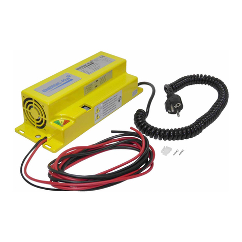
Energic Plus AR-TOP User manual

ENERGIC Plus AR-TOP [V.140 – January 2011] USER S MANUAL
___________________________________________________________________________________________________________________________________________________
PROGRAMMABLE
BATTERY CHARGER
AR-TOP
USER'S MANUAL
V. 1.4.0 January 2011
__________________________________________________________________________________________________________________________________________________
Page 1/32

ENERGIC Plus AR-TOP [V.140 – January 2011] USER S MANUAL
___________________________________________________________________________________________________________________________________________________
1. SAFETY INSTRUCTIONS AND
WARNINGS
GENERAL
Battery chargers can cause injury or death, or damage to other equipment or property, if the user does not
strictly observe all safety rules and take precautionary actions.
Safe practices must be learned through study and training before using this equipment.
Only qualified personnel should install, use, or service this battery charger.
S OCK PREVENTION
Bare conductors, or terminals in the output circuit, or ungrounded, electrically-live equipments can fatally
shock a person. To protect against shock, have competent electrician verify that the equipment is adequately
grounded and learn hat terminals and parts are electrically HOT.
The body’s electrical resistance is decreased hen et, permitting dangerous current to flo through the body.
Do not ork in damp area ithout being extremely careful. Stand on dry rubber mat or dry ood and use
insulating gloves hen dampness or s eat cannot be avoided. Keep clothing dry.
INSTALLATION AND GROUNDING – Electrical equipment must be installed and mantained in accordance
ith all the applicable national and local codes.
A po er disconnect s itch must be located at the equipment. Check the data label for voltage and phase
requirements. If only 3-phase po er is available, connect single-phase equipment to ONLY TWO WIRES of
the 3-phase line.
DO NOT CONNECT the equipment grounding conductor to the third live ire of the 3-phase line as this
makes the equipment frame electrically HOT, hich can cause a fatal shock.
If a grounding conductor is part of the po er supply cable, be sure to connect it to a properly grounded s itch
box or building ground. If not part of the supply cable, use a separate grounding conductor. Don’t remove a
ground prong from any plug. Use correct mating receptacles. Check ground for electrical continuity before
using equipment.
The grounding conductor must be of a size equal to or larger than the size recommended by Code or this
manual.
CHARGING LEADS – Inspect leads often for damage to the insulation. Replace or repair cracked or orn
leads immediately. Use leads having sufficient capacity to carry the operating current ithout overheating.
BATTERY TERMINALS – Do not touch battery terminals hile equipment is operating.
SERVICE AND MAINTENANCE – Shut OFF all po er at the disconnect s itch or line breaker BEFORE
inspecting, adjusting, or servicing the equipment. Lock s itch OPEN (or remove line fuses) so that the po er
cannot be turned ON accidentally.
Disconnect po er to equipment if it is to be left unattended or out of service.
Disconnect battery from charger.
Measure voltage on capacitors and, if there is any voltage reading, ait 5 minutes before to proceed.
Keep inside parts clean and dry. Dirt and/or moisture can cause insulation failure. This failure can result in high
voltage at the charger output.
__________________________________________________________________________________________________________________________________________________
Page 2/32

ENERGIC Plus AR-TOP [V.140 – January 2011] USER S MANUAL
___________________________________________________________________________________________________________________________________________________
BURN AND BODILY INJURY PREVENTION
The battery produces very high currents hen short circuited, and ill burn the skin severely if in contact ith
any metal conductor that is carrying this current.
Do not permit rings on fingers to come in contact ith battery terminals or the cell connectors on top of the
battery.
Battery acid is very corrosive. Al ais ear correct eye and body protection hen near batteries.
FIRE AND EXPLOSION PREVENTION
When batteries are being recharged, they generate hydrogen gas that is explosive in certain concentrations in air
(the flammability or explosive limits are 4.1% to 72% hydrogen in air). The spark-retarding vents help slo the
rate of release of hydrogen, but the escaping hydrogen may form an explosive atmosphere around the battery if
ventilation is poor.
The ventilation system should be designed to provide an adequate amount of fresh air for the number of
batteries being charged. This is essential to prevent an explosion.
Al ays keep sparks, flames, burning cigarettes, and other sources of ignition a ay from the battery recharging
area. Do not break "live" circuits at the terminals of batteries. Do not lay tools or anything that is metallic on
top of any battery.
To prevent arcing and burning of the connector contacts, be sure the charger is OFF before connecting or
disconnecting the battery. The digital display must be completely OFF.
MEDICAL AND FIRST AID TREATMENT
First aid facilities and a qualified first aid person should be available for each shift for immediate treatment of
electrical shock victims.
EMERGENCY FIRST AID: Call phisician and ambulance immediately and use First Aid techniques
recommended by the American Red Cross.
DANGER: ELECTRICAL SHOCK CAN BE FATAL.
If person is unconscious and electric shock is suspected, do not touch person if he or she is in contact ith
charging equipment, battery, charging leads, or other live electrical parts. Disconnect po er at all s itch and
then use First Aid.
Dry ood, ooden broom, and other insulating material can be used to move cables, if necessary, a ay from
person.
IF BREATHING IS DIFFICULT, give oxygen.
IF NOT BREATHING, BEGIN ARTIFICIAL BREATHING, such as mouth-to-mouth.
IF PULSE IS ABSENT, BEGIN ARTIFICIAL CIRCULATION, such as external heart massage.
In case of acid in the eyes, flush very ell ith clean ater and obtain professional medical attention
immediately.
EQUIPMENT WARNING LABELS
Inspect all precautionary labels on the equipment.
Order and replace all labels that cannot be easily read.
__________________________________________________________________________________________________________________________________________________
Page 3/32

ENERGIC Plus AR-TOP [V.140 – January 2011] USER S MANUAL
___________________________________________________________________________________________________________________________________________________
2. DESCRIPTION
The AR-TOP Charger is suitable to charge lead-acid motive batteries.
The operation is completely automatic, and it's managed by a microprocessor control system, composed by a
Main Control Board, installed inside of the charger, and an optional ireless Battery Identification Module
(WBM), that is permanently connected to the battery.
The AR-TOP has t o, selectable char in curves (Wa and WSa).
Wa: typical charge time 10-12 hours
typical start rate 15-18% of the battery capacity C/5
WSa: typical charge time 7-8 hours
typical start rate 23-26% of the battery capacity C/5
The po er conversion system of the AR-TOP and its optimized charging algorithm help to reduce the charging
factor to the minimum value, so the duration of the overcharge/gassing phase and the average temperature of
the battery are minimized.
The AR-TOP Charger is equipped ith a built-in Real-Time Clock, hich allo s the user to program the
desired start time of the day, the full charge time indo and to schedule the eekly equalize cycles.
It is possible to connect the charger to the Fleet Management System DoctorFleet.com, hich allo s to
monitor, program and configure the complete fleet through a WEB based interface, at any time of the day and
from any here in the World, to send automatic messages by email in case of problems.
The AR-TOP charger features an extensive set of advanced functionalities, including an automatic algorithm
for the compensation of the voltage drop of the charging leads. These functionalities are programmable through
an Advanced Confi uration Menu. Please call your service technician for more details.
__________________________________________________________________________________________________________________________________________________
Page 4/32

ENERGIC Plus AR-TOP [V.140 – January 2011] USER S MANUAL
___________________________________________________________________________________________________________________________________________________
3. INSTALLATION OF C ARGER
Conditions of use:
•Operating/Storage temperature: 5°C to 45°C
•Relative humidity: less than 75%
A
__________________________________________________________________________________________________________________________________________________
Page 5/32
WARNING !
The char er can be installed by qualified personnel only!
To avoid the risk of injuries, the user is not allowed to open the cabinet.
Always refer to qualified electricians for installation and service operations.
WARNING !
To prevent fire or shock hazard, do not expose the char er to rain or moisture.
Do not use the e char er in presence of flammable as, because it can enerate sparks!
Do not install the char er near flammable materials.
WARNING !
To reduce the risk of fire, the char er must be installed on a
floor of non-combustible material.
If this is not possible, a floor plate of at least 1,6mm steel extended
at least 150mm beyond the char er on all sides must be installed.

ENERGIC Plus AR-TOP [V.140 – January 2011] USER S MANUAL
___________________________________________________________________________________________________________________________________________________
EQUIPMENT WARNING LABELS
Inspect all precautionary labels on the equipment.
Order and replace all labels that cannot be easily read.
Energic plus AR-TOP battery chargers have been designed to charge lead-acid batteries.
These units can convert the AC input voltage to a DC voltage at the correct level, in order to
charge the battery cells.
The digital electronic control is used to monitor the state of the charge, to automatically turn
off the charger when the charge is complete and to visualize all the necessary information.
All the features of the digital control will be explained in the next chapters.
These are the principal devices included in the charger, available to the user:
•External box;
•Control panel with digital display;
•STOP pushbutton (0-1);
•No.2 Cables for battery connection;
•No.1 Cable for main supply connection;
__________________________________________________________________________________________________________________________________________________
Page 6/32

ENERGIC Plus AR-TOP [V.140 – January 2011] USER S MANUAL
___________________________________________________________________________________________________________________________________________________
Inside of the charger, there are the following devices, not available to the user:
•Power contactor;
•Power transformer;
•Microprocessor controlled electronic board;
•Output fuse;
•Plugs for input voltage selection;
•Plugs for input voltage adjustment.
__________________________________________________________________________________________________________________________________________________
Page 7/32
NOTE
The PLUG/BOARD FOR INPUT VOLTAGE SELECTION is present only in ch rgers with
3x 220 / 380 V c input, nd it's NOT present in ch rgers with 3x440 V c input.
The PLUGS FOR INPUT VOLTAGE ADJUSTMENT re present in ll the ch rgers.

ENERGIC Plus AR-TOP [V.140 – January 2011] USER S MANUAL
___________________________________________________________________________________________________________________________________________________
The charger is marked with a technical label, containing the following data:
•Model;
•Serial number (S/N);
•Weight (kg and lbs);
•Input voltages (V);
•Maximum input current (A);
•Maximum input power (KVA);
•Input frequency (Hz);
•Battery voltage (V);
•Maximum output current (A).
__________________________________________________________________________________________________________________________________________________
Page 8/32
CAUTION !
Allow adequate air circulation to prevent internal heat buildup.
Do not place the unit near materials that may block the ventilation slots.
Do not install the unit near heat sources such as radiators or air ducts, or in a place
subject to direct sunlight, excessive dust, mechanical vibration or shock.
CAUTION !
The operations and settings described in this chapter are
fundamental for the good functionality of the charger.
Improper settings can cause severe damage to the charger and the battery!
Before to install the charger:
Check that the charger input voltage (V) is identical to your AC power supply voltage.
Check that the charger max input power (KVA) is available from your AC power supply.

ENERGIC Plus AR-TOP [V.140 – January 2011] USER S MANUAL
___________________________________________________________________________________________________________________________________________________
AC VOLTAGE SELECTION 3 x 220/380 V
The BOARD FOR INPUT VOLTAGE SELECTION is composed by six terminal blocks, to be
connected in one of the two configurations represented on the picture inside the charger.
PROCED RE:
•Check that the charger is disconnected from AC input and battery;
•Open the cabinet and move the three wires (WHITE) in position 220V or 380V;
•Close the cabinet.
STEP:1 INTERNAL A X TRASFORMER in the middle of the picture
a) 220V 380V
14-0 14-0
_____________ _____________
| | | |
| | | |
|_____________| |__________ ___|
400-X-230-230-0 400-X-230-230-0
- GRAY WIRE
STEP:2
__________________________________________________________________________________________________________________________________________________
Page 9/32

ENERGIC Plus AR-TOP [V.140 – January 2011] USER S MANUAL
___________________________________________________________________________________________________________________________________________________
AC INPUT VOLTAGE ADJUSTMENT
The local AC input voltage must be measured with an adequate voltmeter, then the charger
input must be adjusted by moving the three wires marked with the letters A, B, C on the
PLUGS FOR INPUT VOLTAGE ADJUSTMENT.
PROCED RE:
•Check that the charger is disconnected
from AC input and battery;
•Open the cabinet and move the wires A,
B, C to the desired position.
•Close the cabinet.
__________________________________________________________________________________________________________________________________________________
Page 10/32

ENERGIC Plus AR-TOP [V.140 – January 2011] USER S MANUAL
___________________________________________________________________________________________________________________________________________________
GROUNDING AND LINE CONNECTION
If the charger is to be connected to the AC po er supply ith a flexible jacketed cable, one having a separate
grounding conductor should be used.
If, for any reason, an input cable hich does not include a grounding conductor is used, the equipment must be
grounded ith separate conductor. Minimum size and color coding requirements must be in accordance ith
any applicable national or local code.
__________________________________________________________________________________________________________________________________________________
Page 11/32
WARNING !
The cabinet of the battery char er must be properly rounded to protect
personnel a ainst hazard of electrical shock in case of fault on the char er!
The roundin conductor must have a current carryin capacity equal or
hi her than the current carryin capacity of the AC-input wires.
CAUTION !
Allow adequate air circulation to prevent internal heat buildup.
Do not place the unit near materials that may block the ventilation slots.
Do not install the unit near heat sources such as radiators or air ducts, or in a place subject to
direct sunli ht, excessive dust, mechanical vibration or shock.

ENERGIC Plus AR-TOP [V.140 – January 2011] USER S MANUAL
___________________________________________________________________________________________________________________________________________________
4. OW TO USE T E C ARGER
PRELIMINARY CONTROLS
•Inspect the charger completey for loose scre s, electrical connections or other damages;
•Check that all the ventilation slots are not obstructed to assure proper air flo ;
•Make sure that the charger is installed as instructed in this manual and in accordance ith any applicable
national or local Code.
PROGRAMMING MODE
Turn on the charger by moving the main s itch to position “1”.
The charger ill perform an automatic test of the control circuits, and ill ait for a random delay on start.
The display ill visualize the follo ing messages.
__________________________________________________________________________________________________________________________________________________
Page 12/32
ENERGIC Plus
AR-TOP CHARGER

ENERGIC Plus AR-TOP [V.140 – January 2011] USER S MANUAL
___________________________________________________________________________________________________________________________________________________
HOW TO ACTIVATE SER PROGRAMMING MODE
•Press the button DOWN and keep it pressed for 3 seconds
The display ill sho the message:
•Enter the Programming Pass ord. UP_DW_UP_DW_UP
The display ill sho the message:
HOW TO MODIFY A VAL E
•Scroll bet een the programmable values using the UP/DOWN buttons.
•In order to modify a value, press ENTER and keep it pressed for 2 seconds, until the cursor ill start
blinking over the value that can be modified.
•Modify the value using the UP/DOWN buttons.
•Confirm the modified value by pressing ENTER for 2 seconds, until the cursor ill disappear. At this
point the ne value ill be saved.
HOW TO RET RN TO NORMAL MODE
•Press the buttons UP and DOWN simultaneously.
PARAMETER 1: NOMINAL OUTPUT VOLTAGE
Programmable values: 12-24-36-48-72-80-96-120 Volts
Default value: Nominal voltage of the charger
NOTES:
This parameter should be changed only after replacing the control board of the charger.
__________________________________________________________________________________________________________________________________________________
Page 13/32
SYSTEM READY
xxx V – xxx A
SYSTEM CHECK
PLEASE WAIT ...
EDIT PASSWORD
MOD. SETTING

ENERGIC Plus AR-TOP [V.140 – January 2011] USER S MANUAL
___________________________________________________________________________________________________________________________________________________
PARAMETER 2: NOMINAL CHARGING CURRENT
Programmable values: From 10 to 500 Amps
Default value: Nominal output current of the charger
NOTES:
This parameter should be changed only after replacing the control board of the charger.
PARAMETER 3: GASSING VOLTAGE
Programmable values: from 2.35 to 2.50 V/Cell
Default value: 2.40 V/cell
NOTES:
This charging algorithm of the AR-TOP charger is adaptive, so it's capable of adjusting the charging curve even
if the gassing voltage of the battery deviates significantly from the programmed value.
For this reason, this parameter should be modified only hen using non-standard batteries, or if the operating
temperature is extremely lo or high.
PARAMETER 4: MAXIMUM VOLTAGE
Programmable values: from 2.40 to 2.80 V/Cell, or DISABLED
Default value: 2.80 V/cell
NOTES:
This parameter sets a maximum limit for the cell voltage. If this limit is reached, the charge is terminated and a
specific arning message is given.
PARAMETER 5: C ARGING CURVE
Programmable values: A) WSa - Automatic Algorithm [7-8 hours] [I=22-26% of C]
B) Wa – Finishing Charge 2 Hours [10-12 hours] [I=15-26% of C]
C) Wa – Finishing Charge 3 Hours [10-12 hours] [I=15-26% of C]
D) Wa – Finishing Charge 4 Hours [10-12 hours] [I=15-26% of C]
E) Wa – Finishing Charge 5 Hours [10-12 hours] [I=15-26% of C]
F) Wa – Finishing Charge 6 Hours [10-12 hours] [I=15-26% of C]
G) Wa – Finishing Charge Proportional 25% [10-12 hours] [I=15-26% of C]
H) Wa – Finishing Charge Proportional 33% [10-12 hours] [I=15-26% of C]
I) Wa – Finishing Charge Proportional 50% [10-12 hours] [I=15-26% of C]
J) Wa – Finishing Charge Proportional 66% [10-12 hours] [I=15-26% of C]
K) Wa – Finishing Charge Proportional 75% [10-12 hours] [I=15-26% of C]
Default value: Usually specified at the order.
If not specified, default value is D).
__________________________________________________________________________________________________________________________________________________
Page 14/32

ENERGIC Plus AR-TOP [V.140 – January 2011] USER S MANUAL
___________________________________________________________________________________________________________________________________________________
NOTES:
This parameter allo s to adjust the finishing rate of the charger, depending on the matching Current VS
Capacity that has been chosen at the order. The proper setting of this parameter is useful to maximize the
electrical efficiency of the system, and to minimize the temperature rise of the battery during the finishing
charge.
EXAMPLE 1)
If the battery capacity is 600 Ah and the time available for charging it is 10-12 hours, the recommended AR-
TOP charger should have a nominal current of 100A ( ~16% of C), and the default curve D (Wa Finishing
charge 4 hours) ill be correct.
EXAMPLE 2)
If the battery capacity is 420 Ah and the time available for charging it is 7-8 hours, the recommended AR-TOP
charger should have a nominal current of 100A ( ~25% of C), and it should be programmed to operate ith
charge charging curve A (WSa – Automatic Algorithm).
EXAMPLE 3)
If the battery capacity is 720 Ah and the time available for charging it is 7-8 hours, the recommended AR-TOP
charger should have a nominal current of 120A ( ~16% of C), and the default curve D (Wa Finishing charge 4
hours) ill be correct.
PARAMETER 6: EQUALIZE INTENSITY
Pro rammable values: from 1 to 8 hours
Default value: 2 hours
NOTES:
This parameter allo s to adjust the duration of the eekly Equalize cycle. In most of the cases the default value
of 2 hours orks ell, but sometimes it can be useful to modify this setting, depending on the status of the
battery and on the operating cycle.
IMPORTANT:
The battery ill be equalized only during the programmed time indo (See parameters 10 and 11). If the
Equalize time indo is not set, or it's set too short, the battery ill not receive a sufficient Equalize.
PARAMETER 7: DATE and TIME
Programmable values: Day/Month/Year, Hour/Minute
Default value: Chargers ith European Specs are set by default at GMT+1
Chargers ith North American Specs are set by default at GMT-5
NOTES:
It's fundamental to keep the Real Time Clock set to the correct date and time, in order to use all the time base
functions.
It's necessary to adjust the Clock manually in Daylight saving time periods.
The Charger calculates the Day of the Week automatically.
__________________________________________________________________________________________________________________________________________________
Page 15/32

ENERGIC Plus AR-TOP [V.140 – January 2011] USER S MANUAL
___________________________________________________________________________________________________________________________________________________
PARAMETER 8: START TIME WINDOW
Programmable values: From 00.00 to 23:59
Default value: From 00.00 to 23:59
NOTES:
This parameter sets a time indo during the day in hich the charger is allo ed to start a ne charge cycle.
If a battery is connected outside of this time indo , the charger ill remain in stand-by mode until the
programmed Start time ill be reached.
Once the charge cycle has begun, this time indo is not considered anymore.
PARAMETER 9: FULL C ARGE / OVERC ARGE TIME WINDOW
Programmable values: From 00.00 to 23:59
Default value: From 00.00 to 23:59
NOTES:
This parameter sets a time indo during the day in hich the charger is allo ed to fully charge the battery.
Usually, this parameter is used in opportunity charging applications, ith the purpose of avoiding useless
gassing of the battery during the opportunity charging cycles, and to program a full charge of the battery during
the night.
PARAMETER 10 and 11: EQUALIZE TIME WINDOW
Programmable values: Any day, from 00.00 to 23:59
Default value: From SATURDAY at 12.00 to SUNDAY at 22.00
NOTES:
These parameters set a time indo during the eek in hich the charger is allo ed to fully charge and
Equalize the battery.
It's recommended to set a minimum Equalize time of 12 hours after the normal completion of the charge cycle.
__________________________________________________________________________________________________________________________________________________
Page 16/32

ENERGIC Plus AR-TOP [V.140 – January 2011] USER S MANUAL
___________________________________________________________________________________________________________________________________________________
PARAMETER 12: WBM ENABLE
Programmable values: Enabled, Disabled, Optional
Default value: Disabled
NOTES:
This parameter sets the operation of the charger ith the Wireless Battery Identification module WBM
(optional). Three different operating modes are selectable.
Enabled: When a battery is connected, the charger establishes a communication ith the WBM and uses
the information stored into the WBM to optimize the charge cycle.
Only batteries with WBM installed and properly configured will be charged!
Disabled: The communication of the charger ith WBMs is disabled, and any battery ( ith correct
voltage) ill be charged.
Optional: When a battery is connected, the charger tries to establish a communication ith the WBM.
If a WBM is found, it's used to optimize the charge cycle and to add the battery ID tag on the
charge history log. If a WBM is not found, the battery ill be charged any ay.
PARAMETER 13:WIRED IP ADDRESS RS-485/RESET/TEST WIRELESS
Programmable values: 1 to 254 (Hexadecimal)
Default value: 1
NOTES:
This parameter sets the IP address of the charger, hen it's connected to a ired www.DoctorFleet.com
management net ork.
__________________________________________________________________________________________________________________________________________________
Page 17/32

ENERGIC Plus AR-TOP [V.140 – January 2011] USER S MANUAL
___________________________________________________________________________________________________________________________________________________
5. OPERATION
CONNECTION OF T E BATTERY, AUTOMATIC START
Connect the Battery to the charger, using a connector of adequate size.
When the battery is correctly connected, the charger visualizes the follo ing message:
WIRELESS CONNECTION TO BATTERY IDENTIFICATION MODULE (OPTIONAL)
If the Battery Identification Module is enabled, a fe seconds after the connection of the battery, the charger
ill try to establish a ireless connection. And the display ill visualize the message:
When the ireless connection is active the charger is ready to start the charging cycle. The display visualizes
the message:
At this point, the battery information are transferred to the charger and are visualized on the display.
The charger is no ready to start.
Depending on the programmed start time indo (Parameter 8), the charger may enter in stand-by mode, and
the display visualizes the message:
Where (hh.mm)A represents the real time at that moment, and (hh.mm)B represents the programmed start time.
When the charge begins, the display visualizes the message:
__________________________________________________________________________________________________________________________________________________
Page 18/32
BATT ID MODULE
SEARCHING...
BATTERY
CONNECTED
BATT ID MODULE
CONNECTED
PREPARING
TO CHARGE
DELAYED START
(hh. )A → (hh. )B

ENERGIC Plus AR-TOP [V.140 – January 2011] USER S MANUAL
___________________________________________________________________________________________________________________________________________________
BATTERY VOLTAGE TOO HIGH
If the battery voltage is higher than a maximum threshold, the charge ill not start and the display visualizes
the message:
If this message appears, it's recommended to verify that the nominal battery voltage matches the nominal
voltage of the charger. Probably a rong battery has been connected.
BATTERY VOLTAGE TOO LOW
If the battery voltage is lo er than a minimum threshold, the charge ill not start and the display visualizes the
message:
If this message appears, it's recommended to verify that the nominal battery voltage matches the nominal
voltage of the charger.
Probably a rong battery has been connected.
It's also possible that the battery has been deeply discharged, bringing the voltage belo the minimum value
required for the automatic start the charge.
In this case, it's possible to override the arning message and to start the charge manually, by pushing the
button DOWN for 5 seconds. The AR-TOP ill activate an automatic DESULPHATION-RECOVERY cycle,
after that a standard charging cycle ill begin.
C ARGE CYCLE
When the preliminary controls are complete, the charge starts automatically, and the display visualizes the
follo ing information:
•Battery Voltage [Volt]
•Charging Current [Amps]
•Time of Charge [hours.minutes]
•Capacity Returned [Ah]
__________________________________________________________________________________________________________________________________________________
Page 19/32
BATTERY VOLTAGE
TOO HIGH !!!
BATTERY VOLTAGE
TOO LOW !!!
xx.x V xxx A
xxx Ah x.x t

ENERGIC Plus AR-TOP [V.140 – January 2011] USER S MANUAL
___________________________________________________________________________________________________________________________________________________
The AR-TOP Charger performs an exclusive charge cycle that is composed by stages at constant current and
stages at pulsed current, ith cool do n pauses in bet een.
The management of the charging curve is totally automatic.
Depending on the programming of the Full Charge time indo (Parameter 9), hen the battery approaches
the gassing voltage the charger may suspend the charge (typical opportunity charge cycle). In this situation, the
display visualizes the message:
Where (hh.mm)A represents the real time at that moment, and (hh.mm)B represents the beginning of the Full
Charge / Overcharge time indo .
If the charging curve WSa is selected, the charger ill alternate charging pulses and cool-do n pauses during
the finishing charge. During the pauses, the display visualizes the message “Cooling”.
EMERGENCY STOP
If the battery doesn't reach the gassing voltage ithin a predetermined time, the charger ill suspend the
charge, and it ill visualize the message
In this case, the charge cannot proceed, and it's necessary to disconnect the battery.
It's recommended to control the battery for damaged cells.
AC INPUT BLACK OUT
If there is a black-out of the AC input, hile the charge is in progress, the charger ill shut do n, hile the
charge parameters ill remain in memory.
When the AC input ill be recovered, the charger ill restart the charge cycle automatically, and the display
ill sho the message:
__________________________________________________________________________________________________________________________________________________
Page 20/32
xx.x V Cooling
xxx Ah x.x t
EMERGENCY STOP
VGAS NOT REACHED
RESTART AFTER
POWER SUPPLY OFF
DELAYED OVERCH.
(hh. )A → (hh. )B
Table of contents
Other Energic Plus Batteries Charger manuals

Energic Plus
Energic Plus 124TA1705 User manual

Energic Plus
Energic Plus RX User manual

Energic Plus
Energic Plus NG3 User manual

Energic Plus
Energic Plus NG1 User manual

Energic Plus
Energic Plus SMC User manual

Energic Plus
Energic Plus RE Series User manual

Energic Plus
Energic Plus MVM User manual

Energic Plus
Energic Plus UBC Manual

Energic Plus
Energic Plus TSS-D User manual

Energic Plus
Energic Plus TST-D User manual