Entes MPR-32 User manual

1
MPR-3 SERIES NETWORK ANALYSER USER
MANUAL
INDEX
SAFETY AND WARNINGS........................................................................................................3
Warning..................................................................................................................................3
Safety.....................................................................................................................................3
Warranty.................................................................................................................................3
OPERATING CONDITIONS.......................................................................................................4
INTRODUCTION .......................................................................................................................5
General Features ...................................................................................................................5
Applications...........................................................................................................................6
MPR-3 Series Products..........................................................................................................6
Overview................................................................................................................................7
Terminals ...............................................................................................................................7
Front Panel.........................................................................................................................8
Button Functions.................................................................................................................9
Terminal Structure ............................................................................................................10
INSTALLATION .......................................................................................................................10
3P4W (3 Phase with Neutral) Connection.............................................................................10
3P3W (3 Phase without Neutral) Connection........................................................................11
Aron without Neutral Connection..........................................................................................11
3P4W BLN (3 Phase Balanced with Neutral) Connection.....................................................12
3P3W BLN (3 Phase Balanced without Neutral) Connection................................................12
Connection Test...................................................................................................................13
Line Termination Resistor.....................................................................................................13
OPERATING INSTRUCTIONS................................................................................................14
Measurement Screens .........................................................................................................14
Current, Voltage and Frequency Screens .........................................................................14
Power and Power Factor Screens.....................................................................................15
Energy and Harmonics Screens........................................................................................17
Minimum, Maximum and Demand Screens.......................................................................19

2
Setup Screen........................................................................................................................25
Device Installation Settings..............................................................................................25
Display Settings...............................................................................................................30
Time Settings...................................................................................................................31
RS-485 Communication Settings.....................................................................................33
Input Parameter Settings ..................................................................................................34
Output Parameter Settings................................................................................................35
Pulse Output Settings .......................................................................................................36
Operating Hours Settings..................................................................................................38
Alarm Settings .................................................................................................................39
Reset Settings ..................................................................................................................42
System Settings................................................................................................................44
Reporting Screen..............................................................................................................47
Reading the Records via Modbus .....................................................................................48
TECHNICAL FEATURES AND APPENDIX .............................................................................49
Technical Features...............................................................................................................49
Applicable Standards........................................................................................................50
IEC 61557-12....................................................................................................................50

3
SAFETY AND WARNINGS
Warning
Failure to follow the instructions below mayresult in serious injury or death.
Cut all power before connecting the device.
Do not connect the current measurement inputs directly to the current source. Always connect
the current source using a current transformer.
Once the device is energized, do not remove the front panel.
Do not attempt to clean the device with a solvent or another similar agent. Use only a dry piece of
cloth.
Check the correct connections before energizing the device.
Contact your authorized seller in case of any problems with your device.
Device is only for panel mounting.
F Type fuse must be used and its current limit must be 1 A.
The manufacturing company is not responsible for the consequences resulting from failure to comply with
these precautions.
Safety
Read the entire user manual before using the device.
A switch or circuit breaker must be connected between the network and the auxiliary supply of
the device.
Connected switch or circuit breaker must be in close proximity to the device.
Connected switch or circuit breaker must be marked as the disconnecting device for the
equipment.
Warranty
Device has a 2 (two) year warranty. Any repairs on the device must be done only by the manufacturer.
Otherwise, the device warranty will be void.

OPERATING CONDITIONS
Operating Conditions
Range
Supply Voltage
95 - 270 VAC/VDC(Tolerance up to ±10%)
(Tolerances up to ± 10%)
Supply Frequency
50 ~ 60 Hz.
Maximum Measuring Current
5,5 A
Maximum Measuring Voltage
480 VAC (VLL)
Operating Temperature
-10 ~ +55 ºC
Storing Temperature
-20 ~ +70 ºC
Maximum Ambient Humidity
95%
Communication Speed
2400 ~ 115200 bps
4

5
INTRODUCTION
General Features
o Wide supply range (95 –270 Vrms)
o Custom FSTN display with backlight
o 3 voltage measuring inputs
o 3 current measuring inputs
o 4 language options
o 1MB internal memory
o Real time clock
o Alarm
o Hour counters (Operating hour and total hour)
o Communication via RS-485
o Measured parameters:
Current
Neutral Current
Voltage (Phase-Phase, Phase-Neutral)
Active, Reactive and Apparent Power
Frequency
Active Energy
Reactive Energy
Apparent Energy
Cos φ
Power Factor
Total Active Power
Total Reactive Power
Total Apparent Power
Total Cos φ
Total Power Factor
Total Harmonic Distortion for Current
Total Harmonic Distortion for Phase-Phase Voltages
Total Harmonic Distortion for Phase-NeutralVoltages
o Minimum and Maximum values are available for following parameters:
Current
Phase-Phase Voltage
Phase-Neutral Voltage
Active Power
Reactive Power
Apparent Power
Frequency
Total Harmonic Distortion for Current
Total Harmonic Distortion for Phase-Phase Voltages
Total Harmonic Distortion for Phase-NeutralVoltages
o Demand and Maximum Demand values are available for following parameters measured
with integration time:
Current
Active Power
Apparent Power
o Isolated digital input and output

6
o Capable of recording 256 events
o User password
o Changing primaryand secondaryvalues of current and voltage transformers
o Making measurements on 5 different connectiontype systems: 3 Phase 4 Wires, 3
Phase 3 Wires, 3 Phase Aron, 3 Phase 4 Wires Balanced, 3 Phase 3 Wires Balanced
o Contrast setting
o Backlight setting
o Demand and integration time setting
o Daylight savings time switching
Applications
MPR-3 Series devices are microprocessor-baseddevices which are designed to measure all parameters
of an electrical network, calculate the consumption values and display these on its LCD screen. Events
like interruptions, time and settings changes, reset operations will be recorded in real-time thanks to its
internal flash memoryand Real Time Clock chip. These events then can be accessed and monitored
remotely via RS-485 line with Modbus RTU protocol.
MPR-3 Series Products

7
Overview
Terminals
1. Voltage Inputs
V1 -> 1st Phase Voltage Input
V2 -> 2nd Phase Voltage Input
V3 -> 3rd Phase Voltage Input
N -> Neutral Input
2. Supply Input
3. Digital Input / Output (On models with
two inputs, they are used as IN1 and
IN2 inputs)
Out -> Digital Output
In -> Digital Input
4. RS-485 Input
5. Current Terminals
Back Panel of the model with one input one output K1 -> 1st Phase Current
Input,
L1
-> 1st Phase Current Output
K2 -> 2nd Phase Current Input,
L2 -> 2nd Phase Current Output
K3 -> 3rd Phase Current Input,
L3 -> 3rd Phase Current Outpu
1
2
3
4
5
1
2
3
4
5

8
Back Panel of the model with two inputs
Front Panel
1 –Indicates on which quadrant the network is operating.
2 –Indicates that the displayed value is negative.
3 –Indicates that the measurement is inductive or capacitive
4 –Indicates that the digital output is active.
5 –Indicates that the pulse input is active.
6 –Indicates that password is needed to enter the programmingmenu.

9
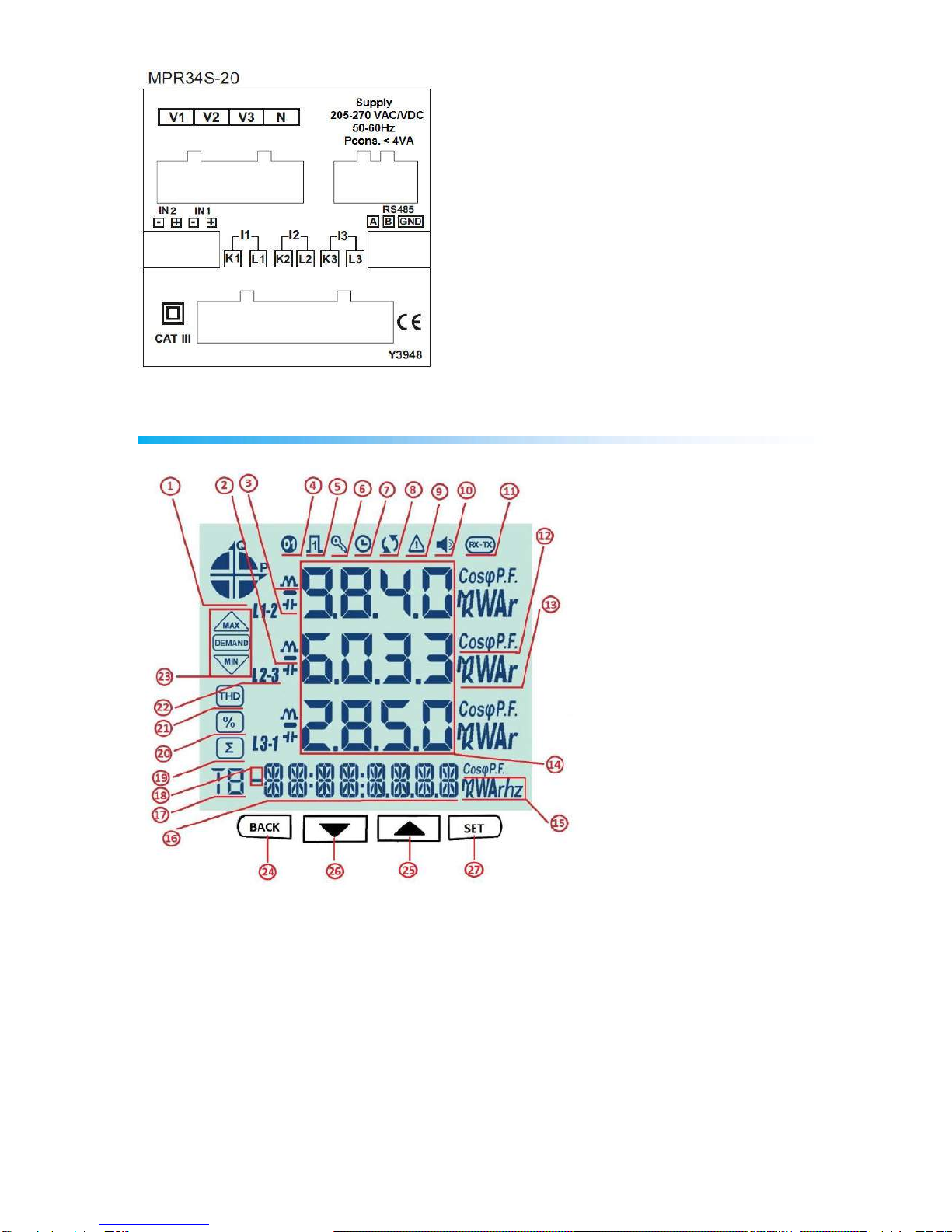
7 –Indicates that the RTC is reset and stays on until RTC is adjusted.
8 –Indicates that there is a phase sequence error.
9 –Indicates that there is a warning
10 –Indicates that the alarm output is active.
11 –Indicates that the communication is active.
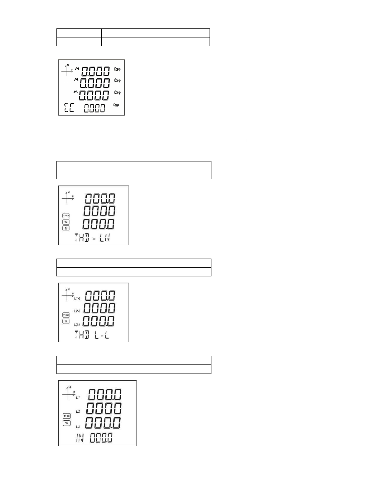
12 –Indicates whether the value is CosØor Power Factor.
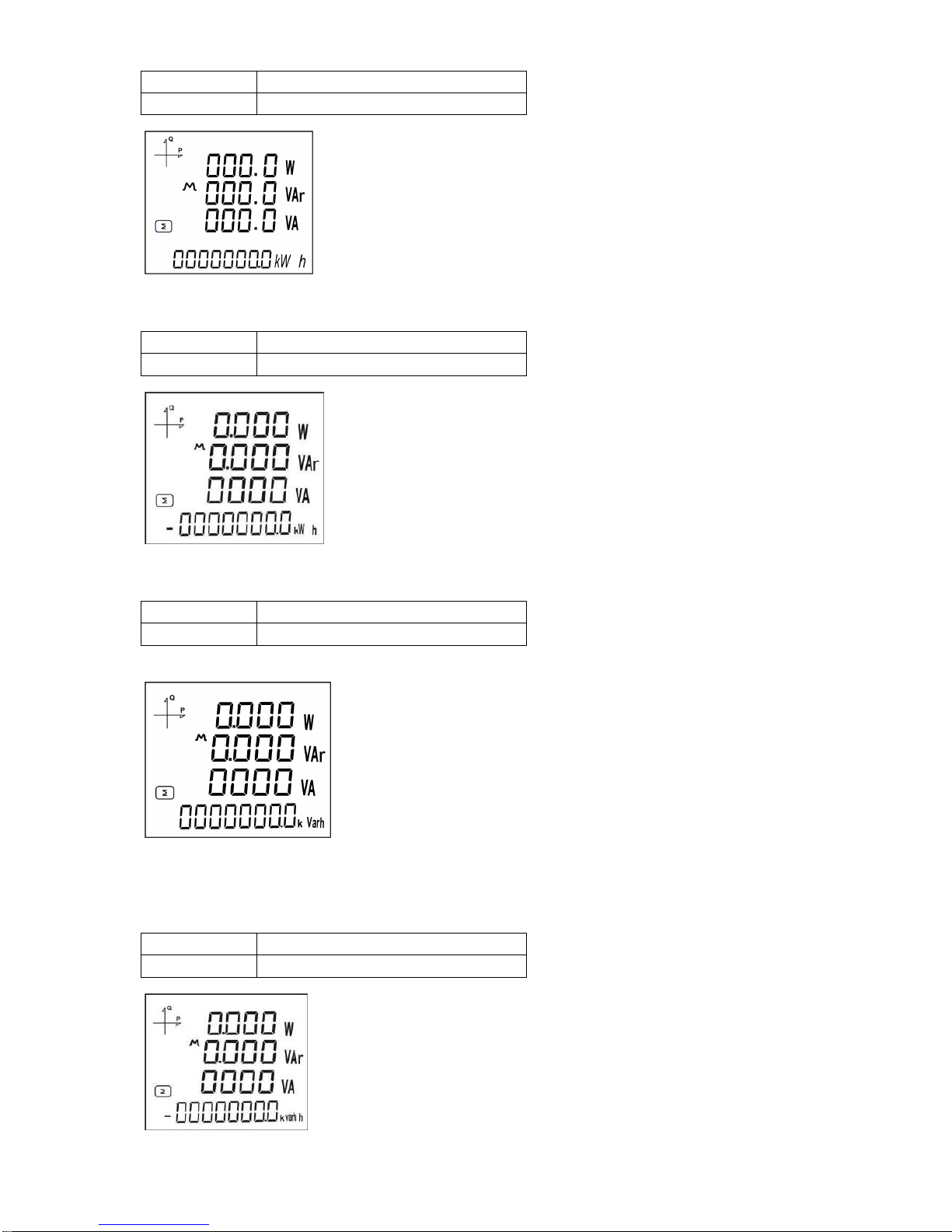
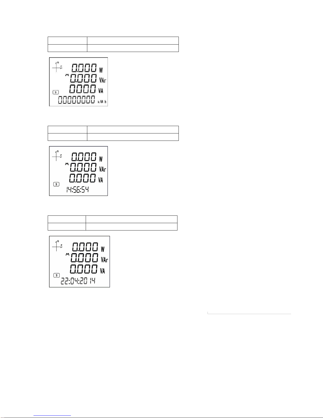
13 –Indicates the unit of the value (W, kVAr, MVA, etc.).
14 –Indicates the measured values of the correspondingscreen.
15 –Indicates the unit of the energy or the correspondingsetting.
16 –Indicates energy value or time.
17 –Indicates for which tariff the energy measurement is.
18 –Indicates that the energy value is negative.
19 –Indicates the total screen. (I.e. Total powers).
20 –Indicates the percent values. (I.e. Harmonics)
21 –Indicates that the displayed values are for Total Harmonic Distortion.
22 –Indicates L1, L2, L3 and L1-2, L2-3 and L3-1 measurements.
23 –Indicates that the corresponding screen is one of Minimum, Maximum, Demand or Maximum
Demand screens.
Button Functions
In addition to their main functions, the 4 buttons on the front panel can be used as shortcut buttons for
easilyreaching screens.
BACK button (24): It has 3 main functions:
Exiting from any menu is done by pressing BACK
button.
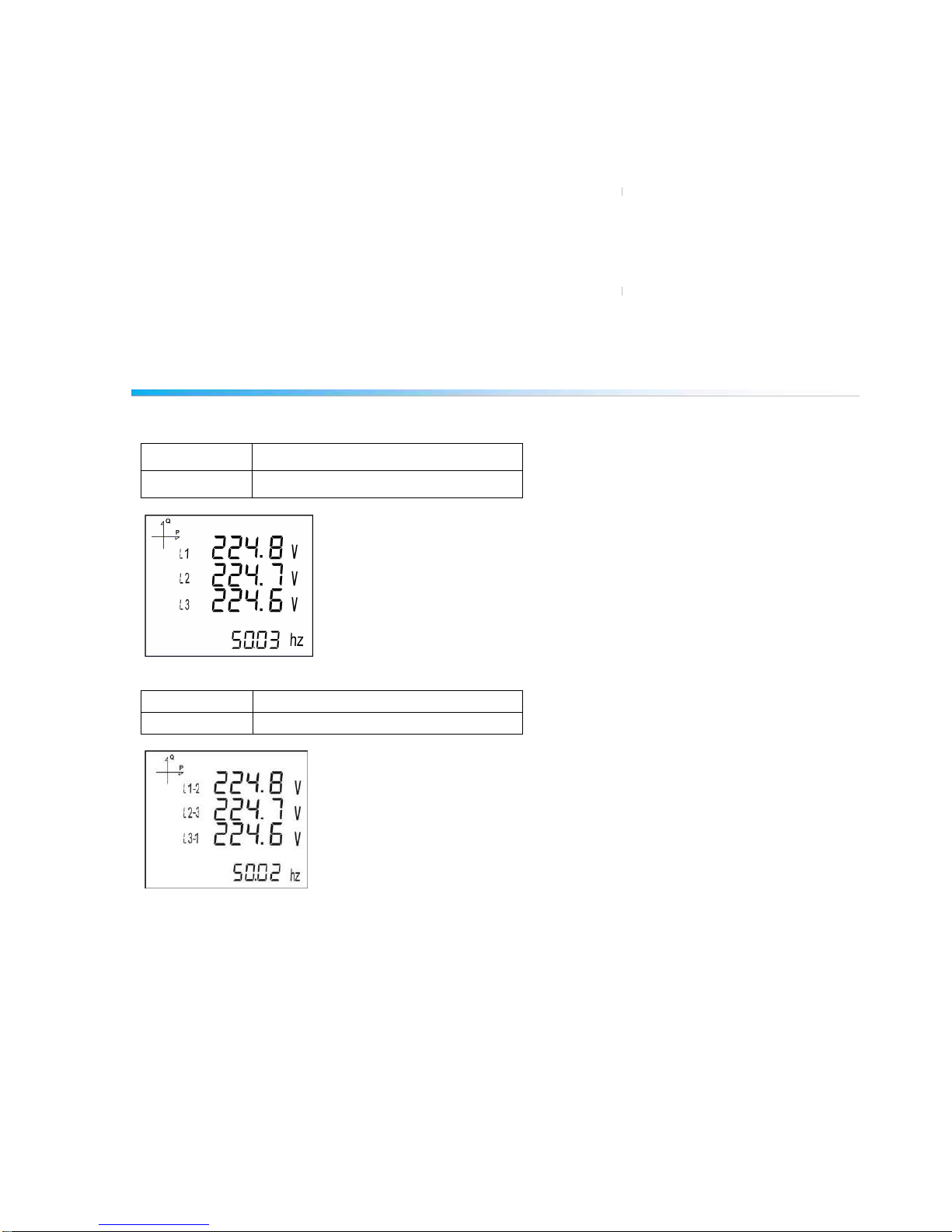
While on measuring screen: As seen on the symbols (V I F) above the button, it is used to
browse between voltage, current and frequency measurement screens.
While on measuring screen: As seen on the symbols (Event) below the button, event screen is
reached when pressed for 3 seconds.
DOWN Button (26) : It has 3 main functions:
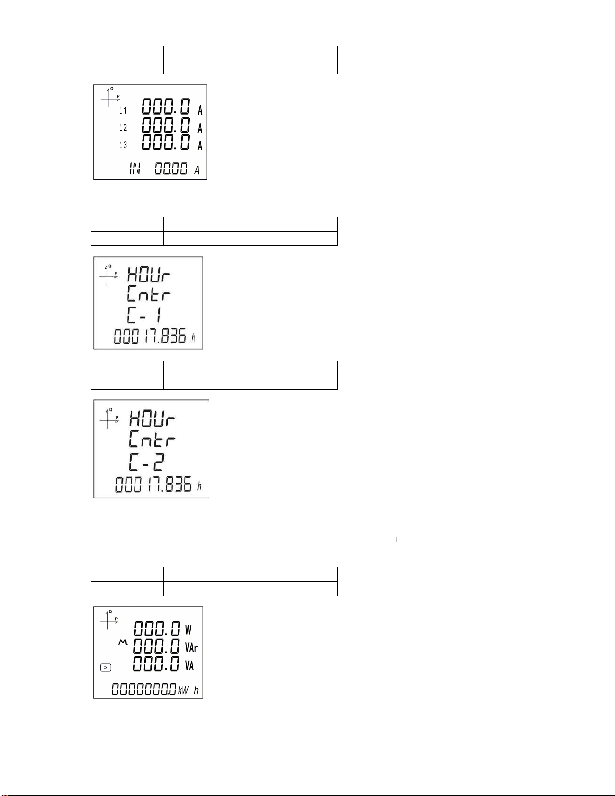
While on measuring screen: As seen on the symbols (P PF) above the button, it is used to
browse between active power, reactive power, apparent power, power factor and Cos φ
measurement screens.
It is used to select the previous digit while entering a numerical value in the menu or to browse
back to a previous menu level.
While on measuring screen: As seen on the symbols (Test) below the button, connection control
is reached when pressed for 3 seconds.
UP Button (25) : It has 2 main functions:
While on measuring screen: As seen on the symbols (E H) above the button, it is used to browse
between energy and harmonics screens.
While on menu screens: It is used to browse between menu options and to decrease a value
during adjustment.
SET Button (27) : It has 3 main functions:
It provides access to menu screens when pressed for 3 seconds. When the PIN is active, a
password is asked before entering the menu. After the correct password is entered, access to
menu is allowed.
It is used to reach the desired adjustment screen and to save the changed settings. Pressing the
button is enough for this operation.
While on measuring screen: It is used to browse between Min, Max, Demand and Max Demand
screens.

10
Terminal Structure
1) 185 - 300 VAC/VDC Supply Input 3 terminal connections (2 pins)
2) Current measuring input terminal block (6 pins): L1 L2 L3 ve N
3) Voltage measuring input terminal block (4 pins): L1 L2 L3 and N
4) RS-485 terminal block (2 pins)
5) Digital Input/Output terminal (4 pins)
INSTALLATION
The device has shunts for current measurement element there for it must be used with external current
transformers.If the device will be use with other analysers on the same panel ,it is recommented that the
device will be the last point on the current measurement line.
Device has 5 different connection configurations. These configurations are explained with diagrams
below:
3P4W (3 Phase with Neutral) Connection
For this configuration, four voltage connections (including neutral line) and three current connections are
used.Voltage inputs should be connected with 100 mA fuses as shown below.

11
3P3W (3 Phase without Neutral) Connection
For this configuration, three voltage connections and three current connections are used.
Aron without Neutral Connection
For this configuration, three voltage connections and two current connections are used.

12
3P4W BLN (3 Phase Balanced with
Neutral) Connection
For this configuration, four voltage connections and one current connection is used.
The device shows the same current value, which is measured from the first phase, for the unconnected
phases.
3P3W BLN (3 Phase Balanced without
Neutral) Connection
For this configuration, three voltage connections and one current connection is used.
The device shows the same current value, which is measured from the first phase, for the unconnected
phases.

13
Connection Test
After finishing device connections, you can check the connection that you’ve done by using the
automatic test function.
When you press the BACK button for 3 seconds, it switches to test mode. During this mode, at least 20%
of the nominal voltage must be applied to the voltage measuring inputs, at least 10% of the nominal
current must be applied to the current measuring inputs and the angle difference between current and
voltage inputs must be less than 30 degrees. These test conditions must be met.
During connection test, the device controls the connections and it can correct them internally or it can
leave the physical correction to the user.
If there’s an error between voltage inputs, it can only be corrected by changing physical connections.
If you encounter Error 12, make sure that all connections are done and minimum current/voltage values
are applied to the device.
On the following table, possible connection errors that maybe encountered during connection test and
their corresponding error codes that are displayed on the device screen.
Test Error Code
Test Code
Description
0
All connections are correct
1
Phase-1 current direction is reversed
2
Phase-2 current direction is reversed
3
Phase-3 current direction is reversed
4
Phase-1 and Phase-2 voltage connections are reversed
5
Phase-1 and Phase-3 voltage connections are reversed
6
Phase-2 and Phase-3 voltage connections are reversed
7
Voltage connection phase sequence will be changed as L1,L2,L3 - L3,L1,L2.
8
Voltage connection phase sequence will be changed as L3,L2,L1 - L3,L1,L2.
9
CT-1, CT-2 will be swapped.
10
CT-1, CT-3 will be swapped.
11
CT-2, CT-3 will be swapped.
12
Test conditions are not met.
Line Termination Resistor
Line termination resistors are used when communication line length is longer than 10 metres. Usage of
accompanying line termination resistor between A and B terminals can enhance communication
performance in case of multiple devices on the same network.

14
OPERATING INSTRUCTIONS
Measurement Screens
Measurement screens, which can be accessed by pressing the related buttons, are explained in this
section.
Current, Voltage and Frequency Screens
BUTTON NAME
DISPLAYED MEASUREMENT SCREEN
BACK (VIF)
VOLTAGE (L-N)
BUTTON NAME
DISPLAYED MEASUREMENT SCREEN
BACK (VIF)
VOLTAGE (L-L)

BUTTON NAME
DISPLAYED MEASUREMENT SCREEN
BACK (VIF)
CURRENT
BUTTON NAME
DISPLAYED MEASUREMENT SCREEN
BACK (VIF)
FIRST HOUR COUNTER
BUTTON NAME
DISPLAYED MEASUREMENT SCREEN
BACK (VIF)
SECOND HOUR COUNTER
Power and Power Factor Screens
BUTTON NAME
DISPLAYED MEASUREMENT SCREEN
DOWN (P PF)
TOTAL POWER
15

BUTTON NAME
DISPLAYED MEASUREMENT SCREEN
DOWN (P PF)
ACTIVE POWER
BUTTON NAME
DISPLAYED MEASUREMENT SCREEN
DOWN (P PF)
REACTIVE POWER
BUTTON NAME
DISPLAYED MEASUREMENT SCREEN
DOWN (P PF)
APPARENT POWER
BUTTON NAME
DISPLAYED MEASUREMENT SCREEN
DOWN (P PF)
POWER FACTOR
16

BUTTON NAME
DISPLAYED MEASUREMENT SCREEN
DOWN (P PF)
COS φ
Energy and Harmonics Screens
BUTTON NAME
DISPLAYED MEASUREMENT SCREEN
UP
THD L-N
BUTTON NAME
DISPLAYED MEASUREMENT SCREEN
UP
THD L-L
BUTTON NAME
DISPLAYED MEASUREMENT SCREEN
UP
THD IN
17

BUTTON NAME
DISPLAYED MEASUREMENT SCREEN
UP
Import Active Energy
BUTTON NAME
DISPLAYED MEASUREMENT SCREEN
UP
Export Active Energy
BUTTON NAME
DISPLAYED MEASUREMENT SCREEN
UP
Import Reactive Energy
BUTTON NAME
DISPLAYED MEASUREMENT SCREEN
UP
Export Reactive Energy
18

BUTTON NAME
DISPLAYED MEASUREMENT SCREEN
UP
Apparent Energy
BUTTON NAME
DISPLAYED MEASUREMENT SCREEN
UP
Time
BUTTON NAME
DISPLAYED MEASUREMENT SCREEN
UP
Date
Minimum, Maximum and Demand Screens
To see the minimum and maximum values of current and voltage, first select the relevant screen with “V I
F” button.
Afterwards, you can display the following screens with MAX/MIN DEMAND button.
19

BUTTON NAME
DISPLAYED MEASUREMENT SCREEN
SET (MAX/MIN)
MAX(Phase-NeutralVoltage)
BUTTON NAME
DISPLAYED MEASUREMENT SCREEN
SET (MAX/MIN)
MIN(Phase-NeutralVoltage)
BUTTON NAME
DISPLAYED MEASUREMENT SCREEN
SET (MAX/MIN)
MAX (Phase-Phase Voltage)
BUTTON NAME
DISPLAYED MEASUREMENT SCREEN
SET (MAX/MIN)
MIN (Phase-Phase Voltage)
20
This manual suits for next models
9
Table of contents
Other Entes Measuring Instrument manuals

Entes
Entes EVM-05C User manual

Entes
Entes MPR-45 User manual

Entes
Entes MPR-53CS User manual

Entes
Entes EPM-4A User manual

Entes
Entes EVM-R3 User manual

Entes
Entes EMG Series User manual

Entes
Entes DCV-10 User manual

Entes
Entes AKC Series User manual

Entes
Entes MPR-53S User manual

Entes
Entes ES3 Series User manual

Entes
Entes EVM-R3 User manual

Entes
Entes MPR-1 Series User manual

Entes
Entes EMK-01 User manual

Entes
Entes MPR-4 Series User manual

Entes
Entes MPR-3 Series User manual

Entes
Entes DCA-10 User manual

Entes
Entes MPR-4 Series User manual

Entes
Entes EVM-15 User manual

Entes
Entes EVM-3S User manual

Entes
Entes EPR-04 Instruction manual