manuals.online logo
Brands
  1. Home
  2. •
  3. Brands
  4. •
  5. Entes
  6. •
  7. Measuring Instrument
  8. •
  9. Entes EVM-3 Instruction manual

Entes EVM-3 Instruction manual

DIGITAL VOLTMETER
EVM-3 / EVM-3C / EVM-3S
EVM-3 (Digital Voltmeter) :
EVM-3 is designed for accurate measuring of the AC RMS voltage and for
saving the minimum and maximum values of the measured voltages. Minimum
and maximum values remain stored in the memory when the ower su ly is
off. This stored values can be read when the ower is on. Although EVM-3 is
mainly used for electrical anels, this device can also be used with any a lication
in which accurate voltage readings should be done between 10-600V. The
measurement (3-4) and ower su ly (1-2) connections are located on the rear
anel and the digital dis lay is centered on the front anel.
EVM-3S (3-Pha e Digital Voltmeter) :
EVM-3S has the same o erating rinci les as EVM-3 but develo ed to measure
voltage in three- hase systems. By using button on the front anel, hase-
hase (L1-L2, L1-L3, L2-L3) and hase-neutral (L1-N, L2-N, L3-N) voltages can
be selected and read from the dis lay.
EVM-3S (72x72) & (48x96) use 3-4 Terminals (L1-N) for su ly in ut. Thus L1-
N voltage must be in o erating voltage range (DU).
EVM-3S (96x96) has a se arated connector for su ly in ut.
.
EVM-3C (Setpointed Voltmeter) :
EVM-3C has the same functions of the EVM-3. In addition to these functions,
an over voltage level and time delay can be set. When the measured voltage
is over the set value, the out ut relay is activated at the end of the adjusted
time delay, generates an alarm signal and dis lay starts blinking.
Minimum and Maximum Voltage :
The minimum and maximum voltage values are stored. User may read or delete
these values. Stored minimum and maximum voltage values remain stored,
when the ower su ly is off.
Setpoint (SP):
When the measured AC voltage between two oints is over the setting value,
the out ut relay is activated in order to generate an error signal, at the end of
the delay time. If the AC voltage is 1.5 times of setting value, out ut relay is
activated without any delay. If the AC voltage value become lower the setting
value before the end of the delay time, the relay resets itself and no tri ing
occurs.
Latch Function ( ):
In case of overvoltage the out ut relay is activated. Latch function is used to
select the out ut relay o eration mode. Either 0 or 1 osition may be selected.
At osition 0: If the voltage is below the setting value, out ut relay releases
automatically, doesnt need any reset.
At osition 1: Even if the voltage is below the setting value, out ut relay
remains activated until the reset and releases only by ressing the set button.
In tant Tripping :
If the AC voltage is 1.5 times of setting value, the out ut relay is activated without
any delay time. This function is user selectable.
At osition 0: Instant tri ing is OFF.
At osition 1: Instant tri ing is ON.
Setting Latch Function (For EVM-3C)
Set
Set
Set
Press the set button.
Press up or down buttons until lt is
dis layed.
Press the set button.
Press up or down buttons until desired
value is dis layed
Press the set button.
Setting In tant Tripping Function (For EVM-3C)
Set
Set
Set
Press the set button.
Press up or down buttons until tP is
dis layed.
Press the set button.
Press up or down buttons until desired
value is dis layed
Press the set button.
Di playing and Deleting Tripping Number (For EVM-3C)
Set
Set
Set
Press the set button.
Press up or down buttons until OP is
dis layed.
Press the set button.
Press up button to delete tripping
number, else do not press any button.
Press the set button.
Adju tment Contact Situation (For EVM-3C)
Set
Set
Set
Press the set button.
Press up or down buttons until CO is
dis layed.
Press the set button.
Press up or down buttons until desired
value is dis layed. (0: Normally o en,
1: normally closed)
Press the set button.
Setting of Delay Time (For EVM-3C)
Set
Set
Set
Press the set button.
Press up or down buttons until dt is
dis layed.
Press the set button.
Press up or down buttons until desired
value is dis layed.
Press the set button.
Di playing Pha e-Pha e or Pha e-Neutral Voltage (For EVM-3S)
Press until desired voltage is dis layed.
E caping the Set Menu (For EVM-3C)
Set
If you do not want to change any
adjustment in the menu;
Press up or down buttons until ESC is
dis layed.
Press the set button.
Factory Setting : Set oint value (s p )
Delay time ( )
Latch ffunction value ( )
Instant tri ing function value
Contact situation ( )
: 250
: 10.0
: 0
: 1 (Instant tri ing is on)
: 0 (Normally o en)
ISO 9001 Q.M.S. Certificate
Setting of Set Point Value (For EVM-3C)
Set
Set
Set
Press the set button.
Press up or down buttons until SP is
dis layed.
Press the set button.
Press up or down buttons until voltage
Set Point value is dis layed. When up or
down buttons are continiously ressed,
the dis lay change quickly.
Press the set button. Di playing Minimum Voltage (For EVM-3C)
Press and hold the down button to see.
Di playing Minimum Voltage (For EVM-3)
Press one time to see the minumum voltage
value
Di playing Maximum Voltage (For EVM-3C)
Press and hold the up button to see.
Press two time to see the maximum voltage value
Di playing Maximum Voltage (For EVM-3)
Deleting the Minimum and Maximum Voltage
Press up and down buttons at the same time.(For EVM-3C)
Press and hold for 2 seconds to delete demands
values (For EVM-3)
If the button is not ressed again within 20 seconds,
EVM-3 turns back automatically in measuring mode. (For EVM-3)
 The decimal oint blinks while the dis lay shows demand values.
s p
0
i
s p
2 0. 0
2 5. 0
s p
s p
2 5 0
2 7 5
s p
0
p
i
s p
0 p
0 0 5
0 0 0
s p
0
0 0 0
e s c
0 0 0
(
p
)
(
p
)
DIGITAL VOLTMETER
EVM-3 / EVM-3C / EVM-3S
PRECAUTIONS FOR INSTALLATION AND SAFE USE
Failure to follow those instructions will result in death or serious injury.
Disconnect all ower before working on equi ment.
When the device is connected to the network, do not remove the front
anel.
Do not try to clean the device with solvent or the like. Only clean the
device with a dried cloth.
Verify correct terminal connections when wiring.
Electrical equi ment should be serviced only by your com edent seller.
No res onsibility is assured by the manufacturer or any of its subsidiaries
for any consequences arising out of the use of this material.
Only for rack anel mounting.
Warning :
a) A switch or circuit breaker must be connected between the network
and the auxiliary su ly in ut of device.
b) Connected switch or circuit breaker must be in close roximity to the
device.
c) Connected switch or circuit breaker must be marked as the
disconnecting device for the equi ment.
d) The ty e of the used fuse must be FF ty e and the current of the used
fuse must be 1A.
e) No need of a vantilator in the installation area
f ) Do not use with generator
g) Attach the instruction of ractical using to the rack anel
EVM-3S (72x72) & (48x96) u e 3-4 Terminal (L1-N) for upply input.
Thu L1-N voltage mu t be in operating voltage range (DU).
Connection Diagram
!
ISO 9001 Q.M.S. Certificate
Technical Data
O erating Voltage (Un),*
O erating Range(DU) : Please look at labels on the device.
O erating Frequency(f) : 50/60 Hz
Accuracy : 1% ±1 digit [(%10-%100) full scale]
Measuring In ut (Vin) : 10-600 V AC (for EVM-3, EVM-3C)
10-300 V AC (Phase-Neutral) (for EVM-3S)
10-500 V AC (Phase-Phase) (for EVM-3S)
Measuring Category : CAT III
Power Consum tion(Pcons) : <4 VA
Burden : <1 VA ( er hase)
Out ut Contact : 5 A, 250 V, 1250 VA (Resistive) (for EVM-3C)
Ins. Tri ing : 1.5 x Set oint (for EVM-3C)
Hysteresis : 4% x Set oint (for EVM-3C)
Delay Time : 0.0 - 99.9 sec. (for EVM-3C)
Equi ment Protection : Double Insulation ( )
Box Protection Class : IP 40
Terminal Block
Protection Class : IP 00
Enclosure : Non-flammable
Ambient Tem erature : -5 OC; +50 OC
Wire Thickness
(for terminal block) : 2.5mm2
Installations : Flush mounting with rear terminals
Dimensions : Ty e PR 18, PR 19, PR 20
Weight : 0.28 kg (for PR 18)
0.30 kg (for PR 19)
0.25 kg (for PR 20)
* Plea e check the device label for proper value.
*Different upply voltage are adju table upon reque t.
Package Dimensions : 32.5 x 22 x 18 cm
Pcs er Package : 16 Pcs (for PR 18)
Package Weight : 4.5 kg
Package Dimensions : 27.5 x 24.5 x 25 cm
Pcs er Package : 12 Pcs (for PR 19)
Package Weight : 3.6 kg
Package Dimensions : 30 x 23 x 17.5 cm
Pcs er Package : 20 Pcs (for PR 20)
Package Weight : 5 kg
Packaging Information
EVM-3S
(72x72)
(48x96)
N
1A
1A
1A
L1
L2
L3
4231
12
EVM-3
1A
L
N
3
Mea uring
Input
4
N
1A
1A
1A
L1
L2
L3
4231
EVM-3S
(96x96)
56
L
1A
N
N
1
2
5
6
Output
Contact
EVM-3C
L
1A
3
Mea uring
Input
4
64EVM000/02-05
Dimen ion
The area Mea urement on The Control Panel
TYPE PR 20 (48x96)
Wall
43mm
63mm
54 mm
50mm
90mm
79.3mm
70mm
TYPE PR 19 (96x96)
50mm
Wall
42mm
82.5mm
75mm
TYPE PR 18 (72x72)
50mm
65.5mm
Wall
Control Panel Cut Out
92mm
92mm
TYPE PR 19 (96x96)
68mm
68mm
TYPE PR 18 (72x72) TYPE PR 20 (48x96)
96mm
48mm
TYPE PR 19 (96x96) TYPE PR 20 (48x96)TYPE PR 18 (72x72)
96mm
96mm
96mm
48mm
72mm
72mm

This manual suits for next models

2

Other Entes Measuring Instrument manuals

Entes EMG Series User manual

Entes

Entes EMG Series User manual

Entes EVM-R3 User manual

Entes

Entes EVM-R3 User manual

Entes EVM-R3 User manual

Entes

Entes EVM-R3 User manual

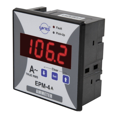
Entes EPM-4A User manual

Entes

Entes EPM-4A User manual

Entes DCA-10 User manual

Entes

Entes DCA-10 User manual

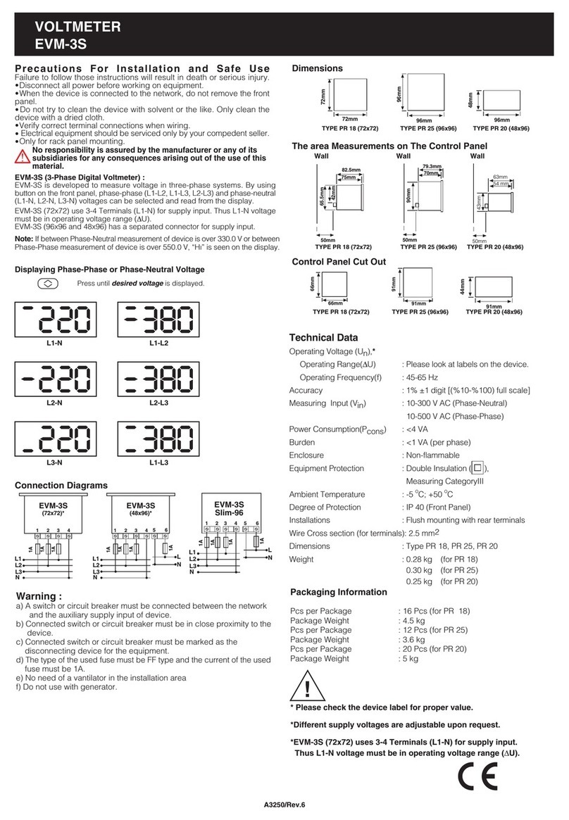
Entes EVM-3S User manual

Entes

Entes EVM-3S User manual

Entes MPR-4 Series User manual

Entes

Entes MPR-4 Series User manual

Entes EPR-04 Instruction manual

Entes

Entes EPR-04 Instruction manual

Entes MPR-45 User manual

Entes

Entes MPR-45 User manual

Entes MPR-53S User manual

Entes

Entes MPR-53S User manual

Entes MPR-1 Series User manual

Entes

Entes MPR-1 Series User manual

Entes MPR-32 User manual

Entes

Entes MPR-32 User manual

Entes MPR-4 Series User manual

Entes

Entes MPR-4 Series User manual

Entes EVM-05C User manual

Entes

Entes EVM-05C User manual

Entes MPR-53CS User manual

Entes

Entes MPR-53CS User manual

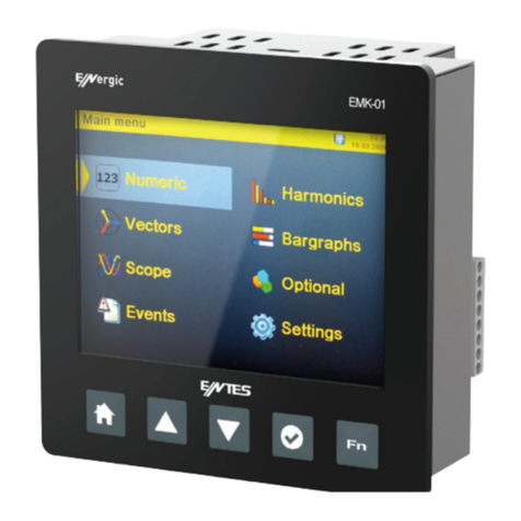
Entes EMK-01 User manual

Entes

Entes EMK-01 User manual

Entes DCV-10 User manual

Entes

Entes DCV-10 User manual

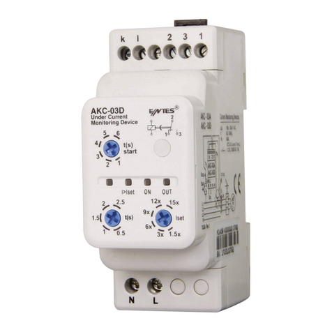
Entes AKC Series User manual

Entes

Entes AKC Series User manual

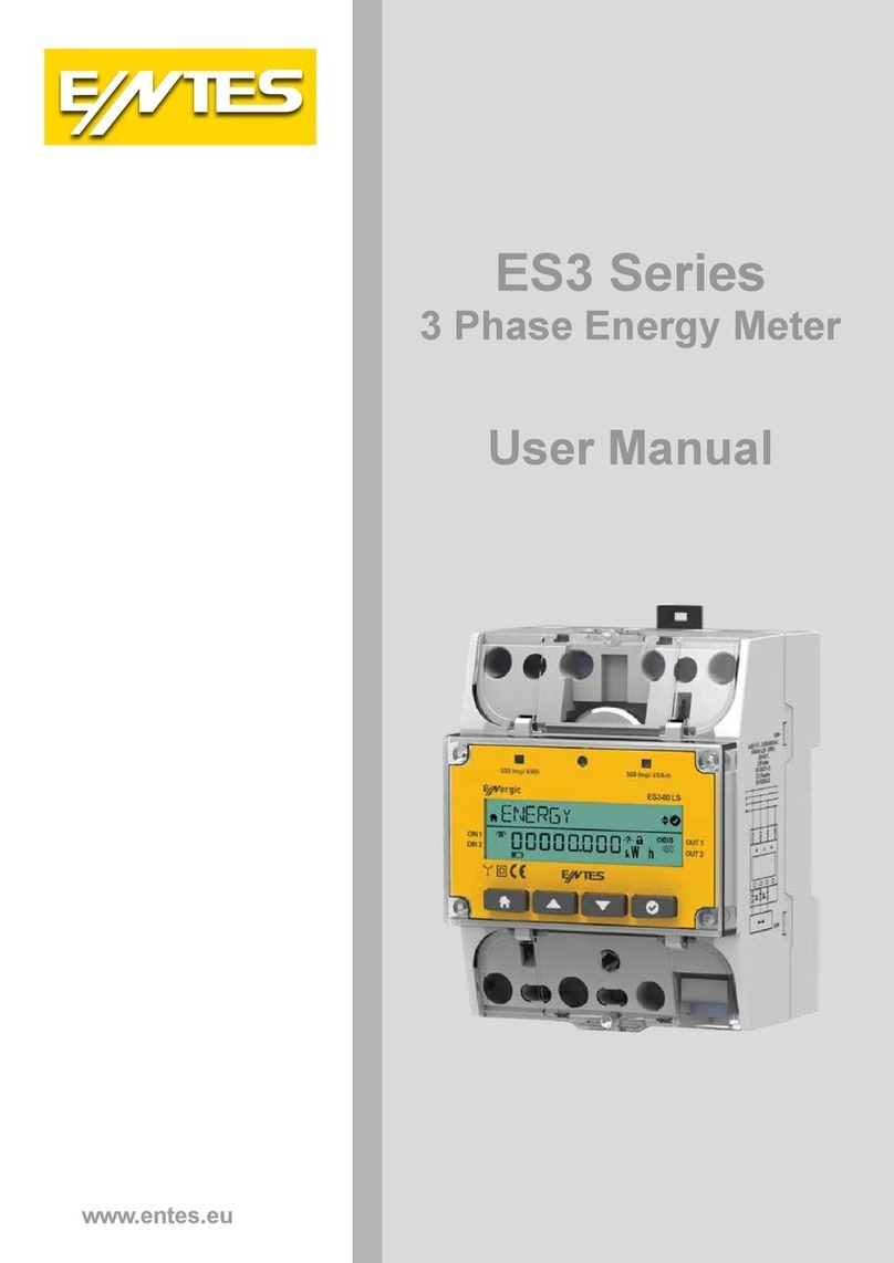
Entes ES3 Series User manual

Entes

Entes ES3 Series User manual

Entes MPR-3 Series User manual

Entes

Entes MPR-3 Series User manual

Entes EVM-15 User manual

Entes

Entes EVM-15 User manual

Popular Measuring Instrument manuals by other brands

YOKOGAWA 2039 user manual

YOKOGAWA

YOKOGAWA 2039 user manual

Reflex EZ-TRAC Field guide

Reflex

Reflex EZ-TRAC Field guide

Hengstler Tico 731.4 operating instructions

Hengstler

Hengstler Tico 731.4 operating instructions

Sekonic L-98 Instruction

Sekonic

Sekonic L-98 Instruction

Kreg Precision KMS7101 Instructional manual

Kreg

Kreg Precision KMS7101 Instructional manual

Dennerle Duomat Evolution DeLuxe Instructions for use

Dennerle

Dennerle Duomat Evolution DeLuxe Instructions for use

Rotronic HygroPalm21 Short instruction manual

Rotronic

Rotronic HygroPalm21 Short instruction manual

ECG CX-920A user manual

ECG

ECG CX-920A user manual

Polymetron 9210 user manual

Polymetron

Polymetron 9210 user manual

Lika Posicontrol LD220 Series user guide

Lika

Lika Posicontrol LD220 Series user guide

YOKOGAWA PH71 user manual

YOKOGAWA

YOKOGAWA PH71 user manual

GASLOCK Indy-Cator operating instructions

GASLOCK

GASLOCK Indy-Cator operating instructions

ASTECH LDM41PN manual

ASTECH

ASTECH LDM41PN manual

Teledyne Lecroy MDA800A Getting started guide

Teledyne Lecroy

Teledyne Lecroy MDA800A Getting started guide

Rohde & Schwarz ZNLE3 Getting started

Rohde & Schwarz

Rohde & Schwarz ZNLE3 Getting started

OXTS AV200 Integration manual

OXTS

OXTS AV200 Integration manual

AEMC PowerPad 8435 user manual

AEMC

AEMC PowerPad 8435 user manual

RIESE SAFE 4 Original Operating Instruction

RIESE

RIESE SAFE 4 Original Operating Instruction

manuals.online logo
manuals.online logoBrands
  • About & Mission
  • Contact us
  • Privacy Policy
  • Terms and Conditions

Copyright 2025 Manuals.Online. All Rights Reserved.