Entes MCB-200 User manual

A6698 / Rev.2 www.entes.com.tr
MCB-200 MULTIFUNCTION DIGITAL TIME RELAY
With 1 CO contact
Operating Manual
Dudullu OSB; 1. Cadde; No: 23 34776 Umraniye - ISTANBUL / TURKEY
Tel : +90 216 313 01 10 Fax : +90 216 314 16 15
12
Precautions for Installation and Safe Use
If below precautions are not properly observed and carried out, it may result in cases with injury or
death.
· Disconnect power before working on the device.
· When device is connected to the network, do not remove the front panel.
· Do not clean the device with solvent or similar items. Only clean with dry cloth.
· Verify correct terminal connections before energizing the device.
· Install the device on the electrical panel.
· Contact your authorized reseller in case problems occur with your device.
·No responsibility is assured by the manufacturer or any of its subsidiaries for any
consequences rising out of not following above precautions.
1. INTRODUCTION
MCB-200 is a multifunction digital timer with 1 CO contact. It offers wide time adjustment range
between 0.2-9999 seconds and 0.1-9999 minutes.
MCB-200 has 15 different functions with wide adjustable time ranges. The main application area is
the industrial and automation control systems. Wide supply voltage range and one output relay with
C/O contacts offer the highest flexibility for many applications.
MCB-200 has two dry contacts for START and STOP inputs
1.1 Product Features
MCB-200 has the following features:
· Lithium battery
· 15 different functions
· 0.2-9999 seconds/0.1-9999 minutes time range
· 1 relay output
· Start-Stop dry contact inputs
· Custom design LCD with green backlight
· SET, ESC, UP, DOWN buttons are located on front panel for easy programming
· Degree of protection for enclosure IP 40, for terminals IP 20
· PK25 DIN Rail mounting
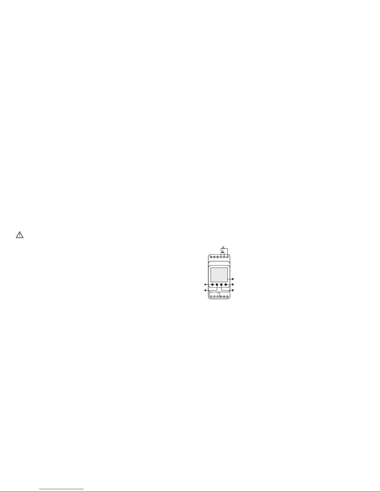
1.2 Hardware Features
To operate functions with external triggering, MCB-200 has the necessary START and STOP dry contacts.
LCD
UP BUTTON
SET BUTTON
ESC BUTTON
DOWN BUTTON
Stop
Start
4 5 6
C NC
NO
R1
3 4
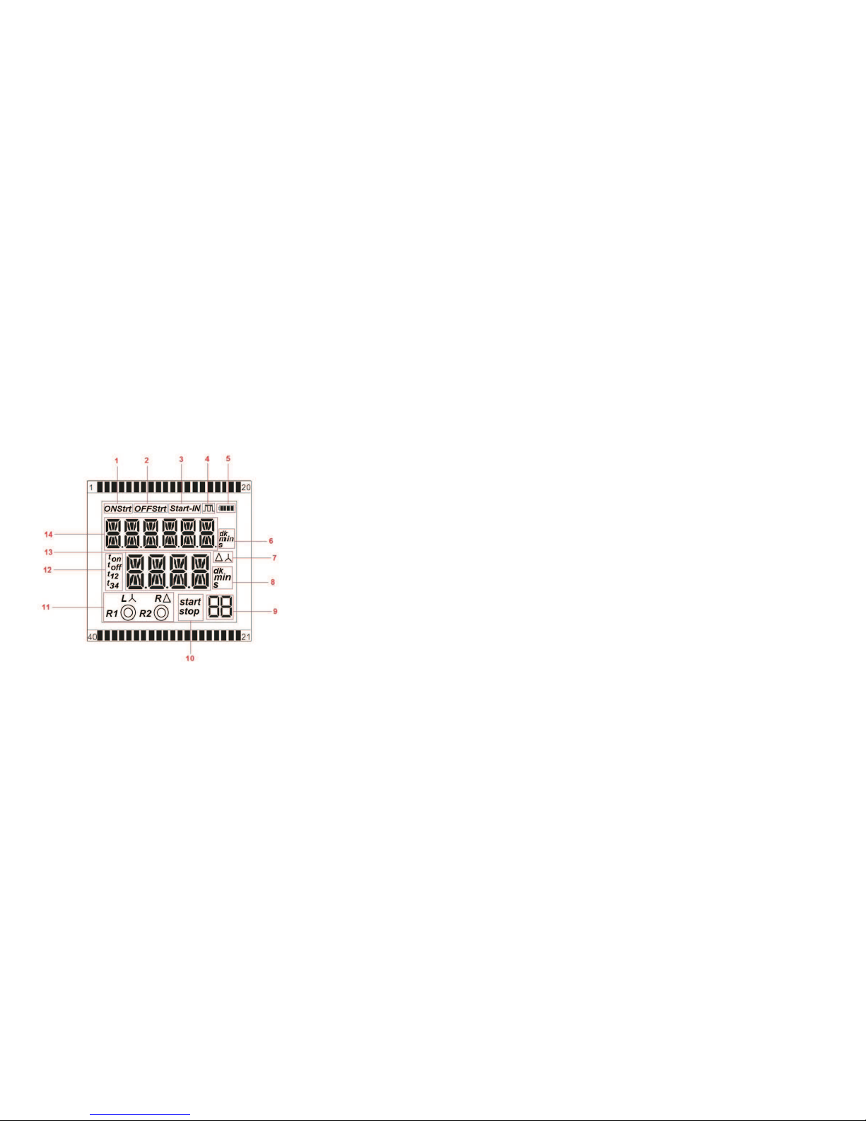
1.2.1. Display
1.2.3 Output
MCB-200 has one changeover relay output. According to VDE 0110 and IEC 60947-1 standards; switching
capacity of relay output is 8A, 2000VA, 250 V. and maximum electrical life time is 1x 10^6.
1. ONSrt : Indicates that the relay will start as closed.
2. OFFSrt: Indicates that the relay will start as open.
3. Srt-Input Icon: Indicates that the function is started with external input.
4. Indicates whether function trigger is Level or Edge.
5. Battery
6 and 8. min sec : Indicates whether timing unit is minute or second
7. Time setting indicator for Star-Delta function
9. Numeric Two Digits: Show function number.
10. Stop: Indicates that stop input is active. Start: Indicates that stop input is active.
11. When R1 or R2 relays are activated, the center of the circles are turned on. Rand Lletters are used
to indicate left or right direction when inverser relay function is selected. Star-Delta: Indicate the output
relay state in Star-Delta function.
12. Indicates the time type of functions.
13. In the main menu, it shows the elapsed time.
14. In the main menu, it shows the entered time. In the settings menu, it shows the function names.
1.2.2 Button functionality
SET, ESC, UP and DOWN buttons help to select functions and set their times.
UP button goes to previous menu item in Settings Menu and increase selected parameter value.
DOWN button goes to next menu item in Setting Menu and decrease selected parameter value.
SET button is for entering data. When pressed at least 3 seconds, Setting Menu is selected.
ESC button exits from a menu.
6
1.2.4 Inputs
1.2.4.1 Start Input and Stop Input:
These inputs are voltage-free dry inputs.
Start Input: For some of the functions, output depends on the state of the start input or input pulses
from start input. When user shorts two terminals of this input, start input activates.
Stop Input: When stop input applies, the timing pauses with stop input's leading edge. When stop
input is removed, the timing continues to count from it's last value with stop input's trailling edge.
Stop input affects all functions as the same without any exception. When user shorts two terminals
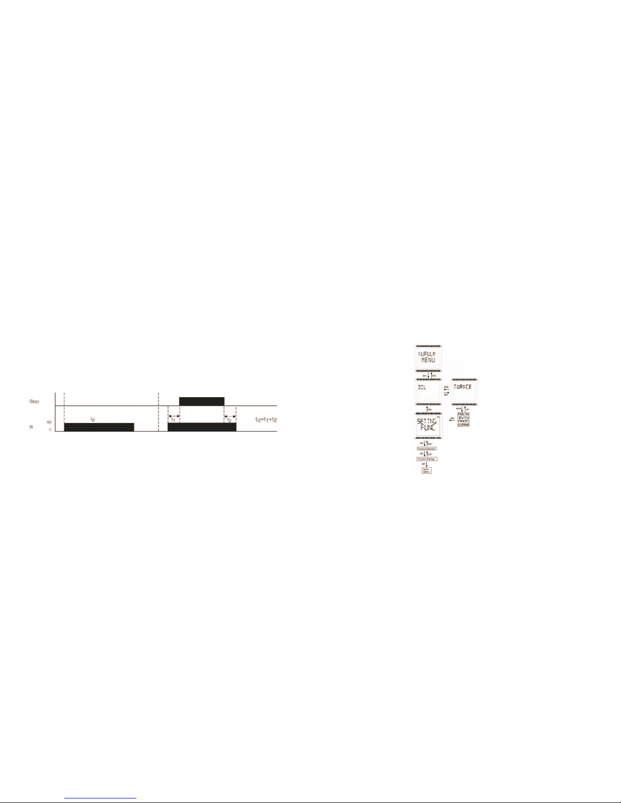
An Example: This function needs td delay time to release relay. When stop input is applied, it stops
counting and saves the time t1. With stop input's trailing edge, counting continues from the saved
time t1 until delay time td (Here td=t1 + t2). While stop input is active, the relay doesn't change its
position.
5
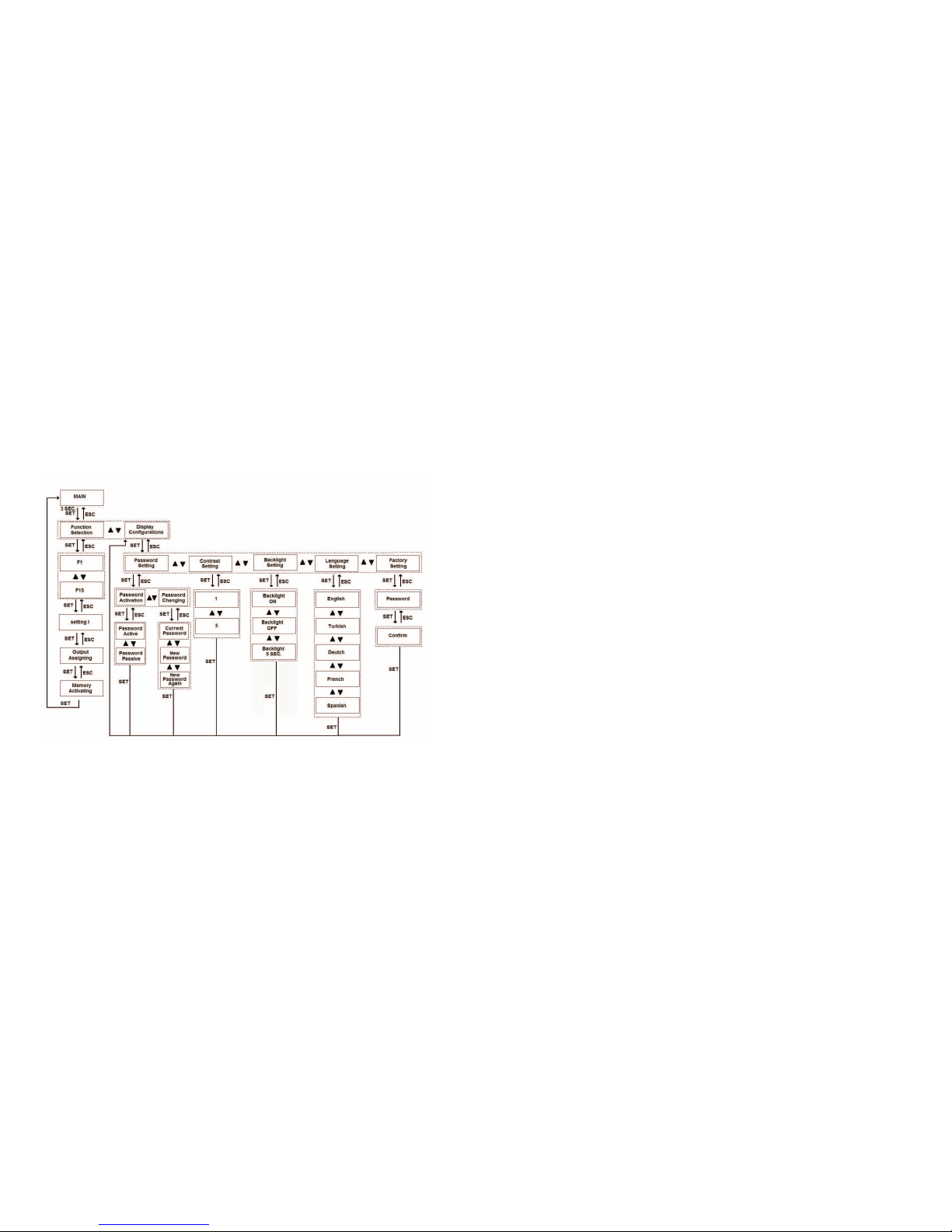
2. OPERATING INSTRUCTIONS
When the device is taken out of the box, an installation menu will be displayed. Language and function
settings are done in this menu as seen in the figure below. Afterwards, device returnss to main menu and
starts operating.
Stop : Stop Input
R : R1 Relay
td : Delay Time
t1 : Time elapsed until Stop Input is activated (t1<td)
t2 : Time elapsed after Stop Input is deactivated (td=t1+t2)
ON
OFF

8
7
1. On Delay / Start by external trigger leading edge
This funcition is controlled by start input. Time counting starts with the leading edge of the start pulse;
at the end of time td the output relay is activated and remain activated while start input pulse is ON
Basic settings map is shown below. There are two main submenus as function selection and display
settings.
Function Selection Submenu: A new function is set from function selection menu. In this submenu,
user chooses a function, sets t parameter/parameters for selected function; assigns relay output.
Display Configurations Submenu: Changing password, adjusting contrast, activating backlight
or changing language is done from this submenu.
S : Start Input
R : R1 Relay
td : Delay Time
<td td
td
R
S
OFF
ON
NO
C<td

9 10
2. On Delay / Start by external edge re-trigger
This funcition is controlled by start input. Time counting starts with the leading edge of the start pulse;
at the end of time td the output relay is activated and remain activated until next start pulse is applied.
3. Off Delay / Start by external trigger trailing edge
This function is controlled by start input. Output Relay is activated when start pulse is applied and remain
on; time counting starts with the trailing edge and output relay is deactivated at the end of delay time td
lf trigger pulse occur during time counting period, elapsed time is reset.
R
S
OFF
ON
NO
Ctd td R
S
OFF
ON
NO
C
td

1211
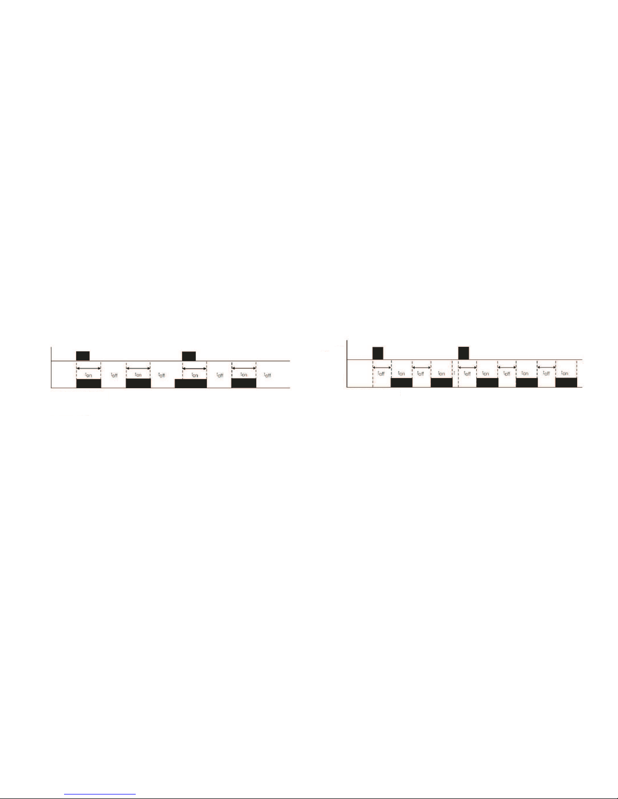
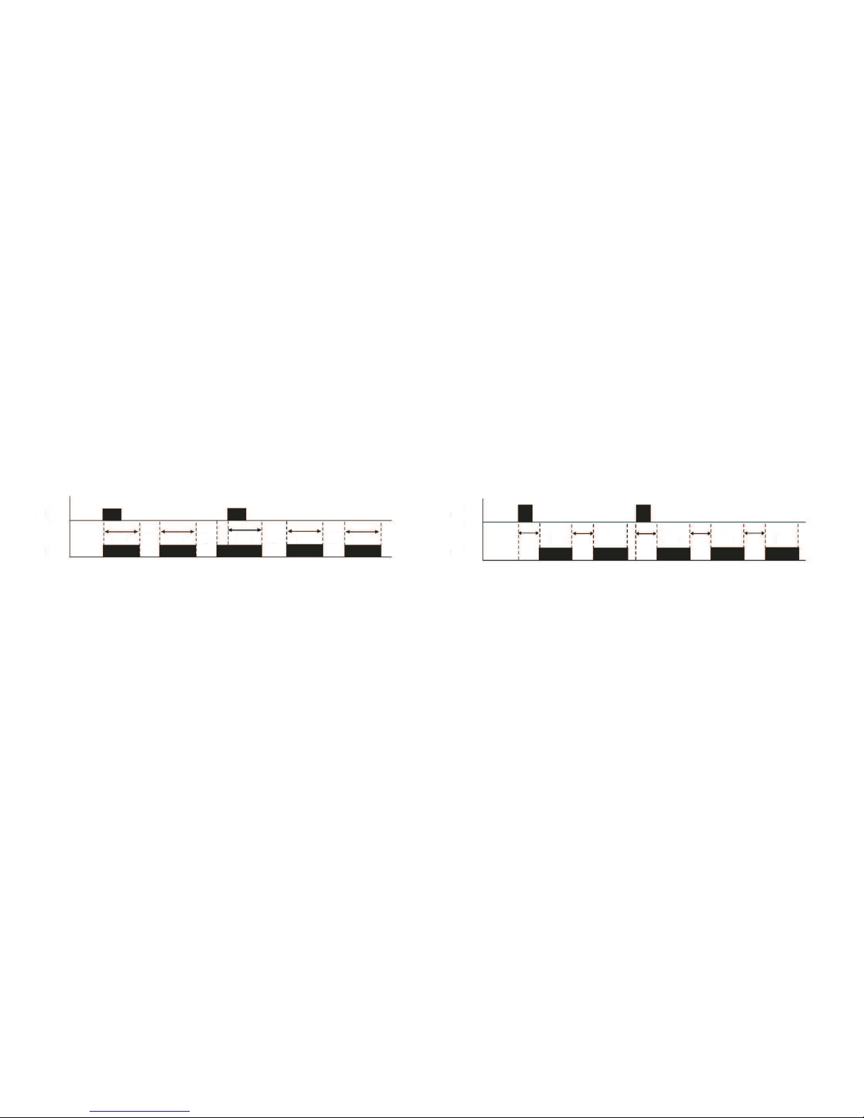
4. Symmetric Flasher / Start by external trigger leading edge / Relay ON start
This function is controlled by start input. With the leading edge, output relay is activated and remain
on during ton. After that, it is deactivated and toff starts. This cycle is repeated while start
pulse is on (high).
5. Symmetric Flasher / Start by external trigger leading edge / Relay OFF start
Function is similar to the ON Start version (function 4) with the exception that the output relay start
as passive.
ON
KAPALI
S
RNO
C
OFF
OFF
S
RNO
C
ON

S
RNO
C
OFF
ON
ton ton ton ton ton ton
toff toff toff toff
13 14
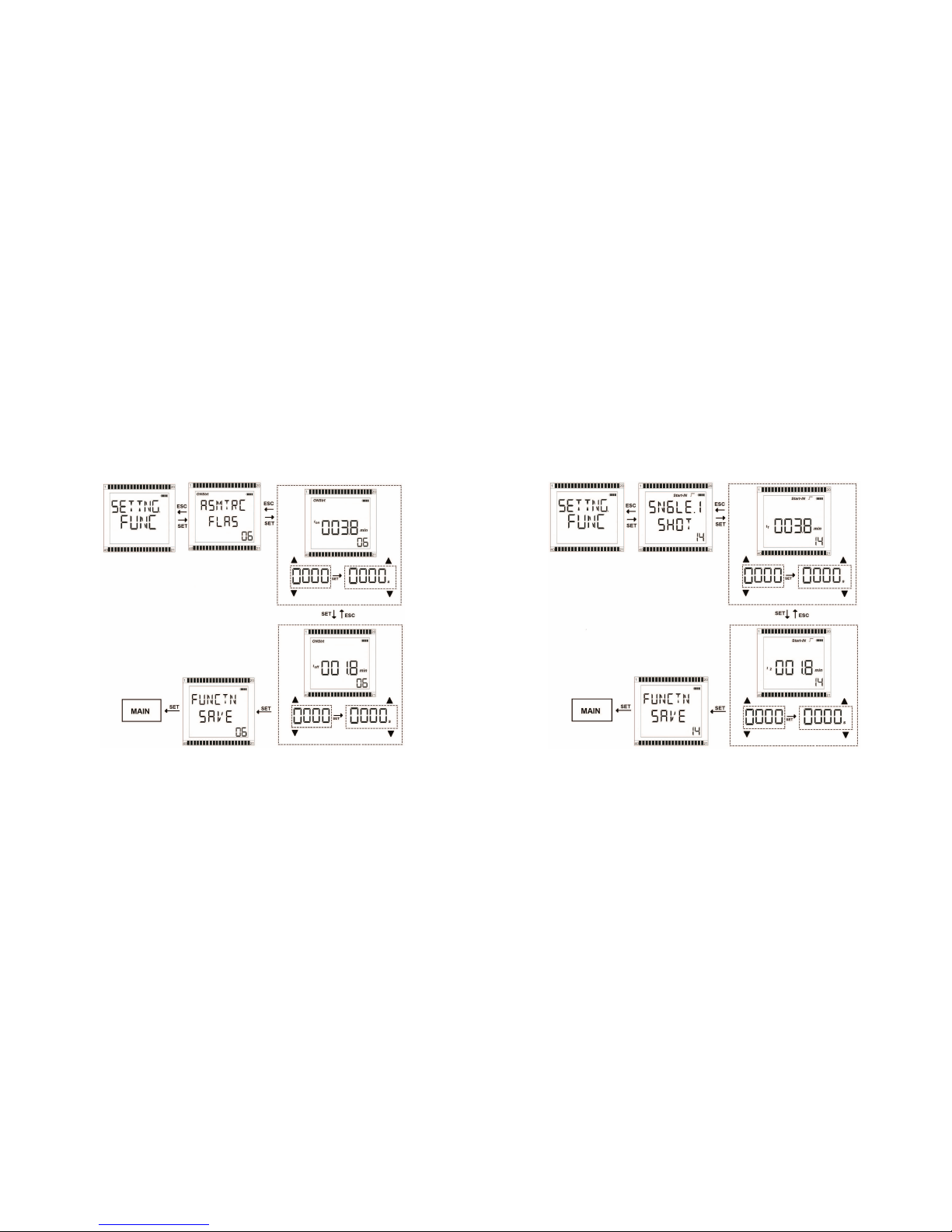
6. Asymmetric Flasher / Start by external trigger leading edge / Relay ON start
This function is controlled by start input. With the leading edge, output relay is activated and remain
on during ton. After that, it is deactivated and toff starts. This cycle is repeated while start
pulse is on (high).
7. Asymmetric Flasher / Start by external trigger leading edge / Relay ON start
Function is similar to the ON Start version (function 6) with the exception that the output relay start as
passive.
S
RNO
C
OFF
ON
toff toff toff toff toffton ton ton ton ton
15 16
8. Symmetric Flasher / Start by external edge - retrigger / Relay ON start
This function is controlled by start input. With the leading edge, output relay is activated and remain
on during ton. After that, it is deactivated and toff starts. This cycle is repeated until the next edge-
retrigger pulse. If a trigger pulse occur during ton, time counting is reset and ton time counting
is restarted.
9. Symmetric Flasher / Start by external edge - retrigger / Relay OFF start
Function is similar to the ON Start version (function 8) with the exception that the output relay start
as passive.
ON
KAPALI
S
RNO
C
OFF
ON
KAPALI
S
RNO
C
OFF
17 18
10. Asymmetric Flasher / Start by external edge - retrigger / Relay ON start
Function is similar to the Symmetric version (function 8) with the exception that ton and toff
times can be set differently.
11. Asymmetric Flasher / Start by external edge - retrigger / Relay OFF start
Function is similar to the Symmetric version (function 9) with the exception that ton and toff times can
be set differently.
R
S
OFF
ON
NO
C
ton ton ton ton tontoff toff toff toff
R
S
OFF
ON
NO
C
toff toff toff toff toffton ton ton ton tont

19 20
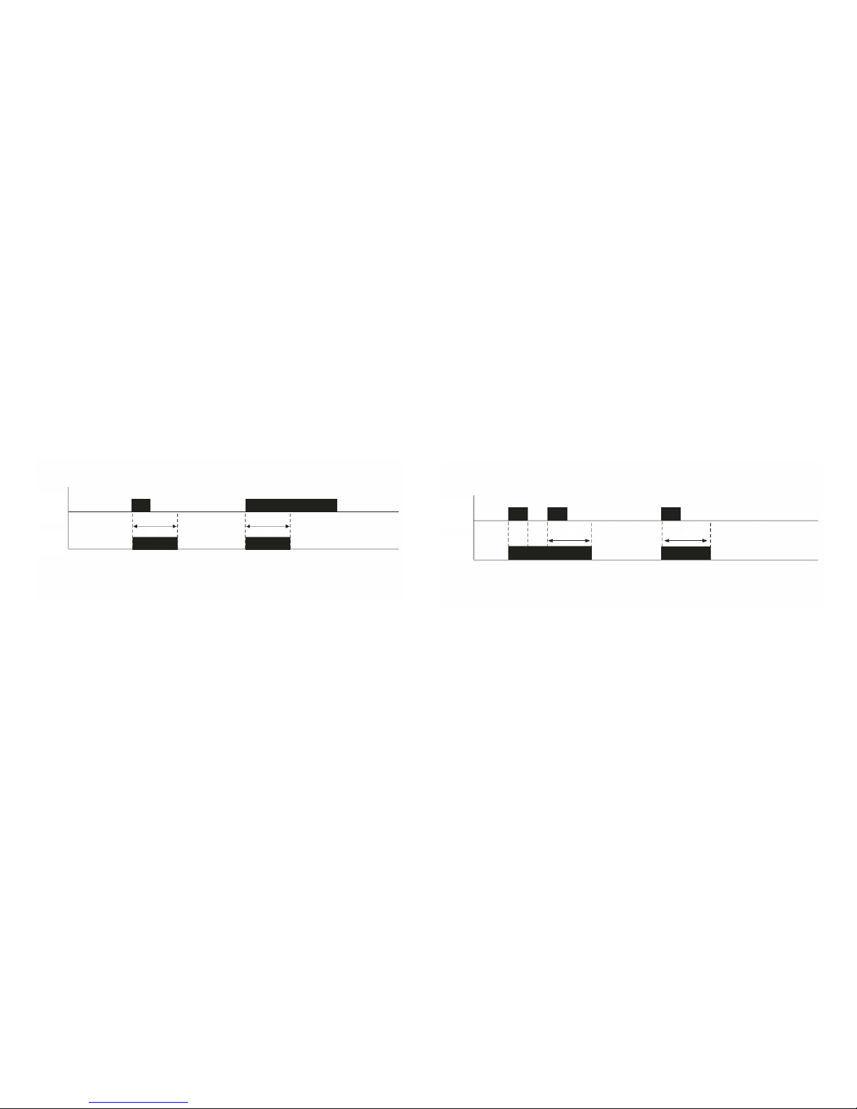
12. Adjustable ON Delay by external trigger leading edge
This function is controlled by start input. The cycle starts with adjustable toff delay time. At the
end of delay time, output relay is activated and remain activated during ton. If the Start input is
deactivated and activated, function will be reset.
13.Adjustable and Resettable ON Delay Pulse by external trigger leading edge
This function is controlled by start input. The cycle starts with adjustable toff delay time after a pulse
is created at the Start input. At the end of delay time, output relay is activated and remain activated during
ton. If a re-trigger pulse occurs during toff, elapsed time is reset and toff counting is restarted.
SON
OFF
RNO
C
t1 t1 t2 t1 tt<t2
SON
OFF
RNO
C
t<t1 t1 t2 t1 t2
21 22
14. Adjustable OFF Delay Pulse by External Trigger Leading Edge
This function is controlled by start input. With the leading edge of the external trigger, output relay is
activated and remain on during td.
15. Adjustable OFF Delay Pulse by External Trigger Leading Edge Re-trigger
This funcition is controlled by start input. The cycle starts with adjustable td delay time and output
relay is activated. It remains activated during this period. If a re-trigger pulse occurs during td period,
elapsed time is resett and td counting is restarted.
SON
OFF
RNO
C
tt
SON
OFF
RNO
C
tt

23 24
2.2 Settings
2.2.1 Function Selection:
Function sub-menu is reached by pressing SET button in Settings menu. The functions that the device
offers can be browsed with UP or DOWN buttons. The user selects the desired function enters its
adjustment menu by pressing SET button.
25 26
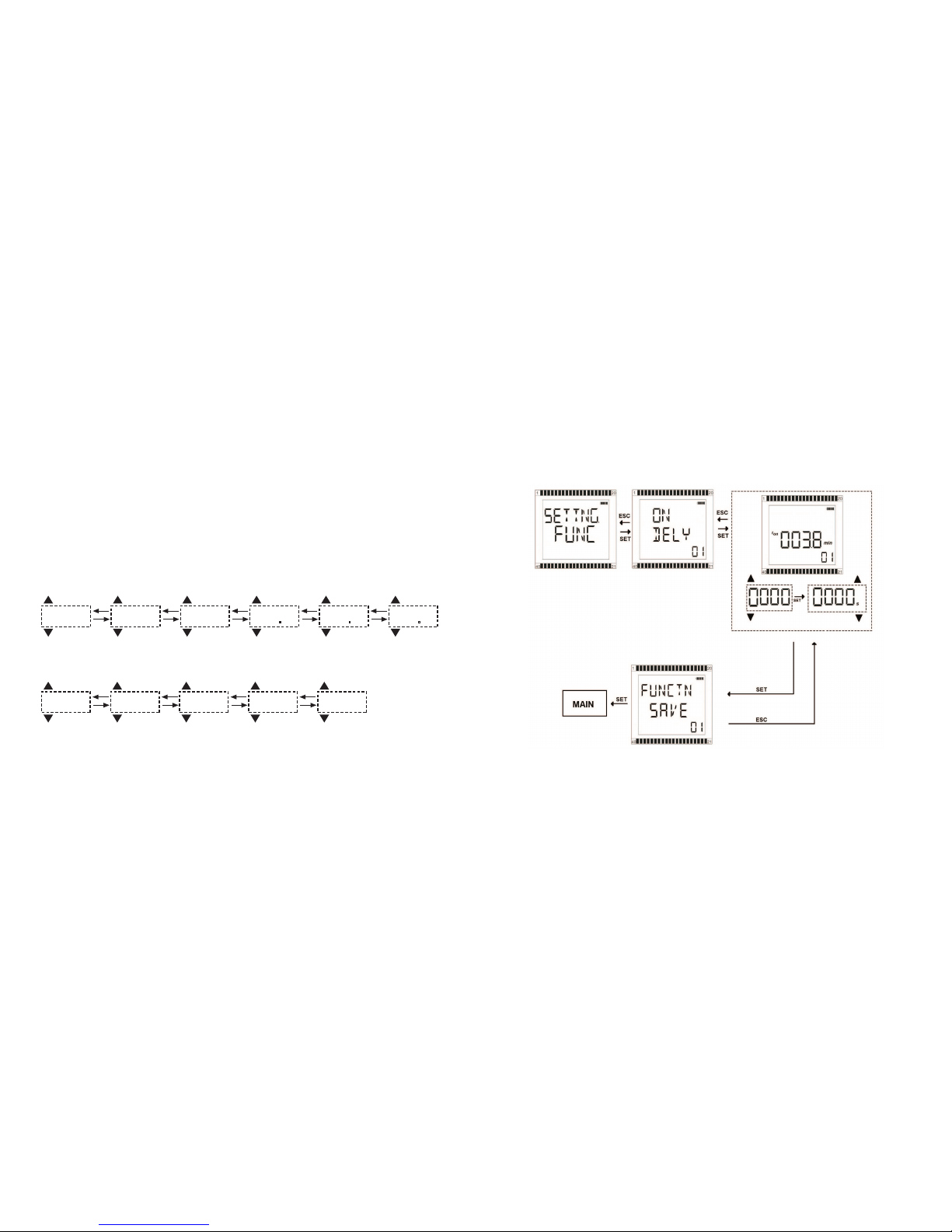
2.2.2 Time Setting :
After selecting the function, user sets t value/values according to the application need.
Time range for t is between 0.1 seconds-9999 seconds and 0.1 minutes-9999 minutes. Setting
starts from left digit towards right digit. User uses UP button to increase value of the digit and
DOWN button to decrease. The user presses SET button to move to the next digit on the right
and the ESC button to move back to a previous digit. After entering a number, user selects unit
(minutes or seconds) by pressing UP or DOWN. Finally, the selected values are stored by
pressing SET button.
FUNCTION SETTINGS
ON Delay :
Example Interval (0.1 - 9.9) :
Example Interval (10 - 9999) :
0000
SET
ESC
0000
SET
ESC
0030
SET
ESC
003
SET
ESC
SET
ESC
0 003 8003 8
2000
SET
ESC
2500
SET
ESC
2570
SET
ESC
2578
SET
ESC
2578
s
dk
27 28
Flasher : Single Shot

30
29
One Shot : 2.2.3 Display Settings :
In this submenu; user can set password, contrast,
backlight, language and return to factory settings.
In password submenu, user can activate or
deactivate the password. To change password,
user enters current password first, then new
password twice. User can change contrast
level from 1 to 5. Also user can choose the
backlight operation as on, off, on for 5 seconds.
Five languages as Turkish, English, German,
French, Spanish can be selected.

31 32
3 MAIN DISPLAY
This is an example to explain main screen use.
- Top line displays the function. In this case; Onstrt (ON
start), Strt- Input (Start Input) and Edge Trigger is selected.
- First line displays the set time value; min. icon indicates
the time scale.
- Second line displays the elapsed time value; min. icon
indicates the time scale
- start icon indicates that Strt-Input is active.
- The number 01 indicate that 1st function is selected.
- icon is turned on and indicate that R1 relay is activated.
When UP or DOWN button is pressed while on the main menu, the name of the selected function is
displayed. By pressing the ESC button, main display is accessed again.
Connection Diagram : Dimensions :
TYPE PK25

33 34
Technical Features
Input Circuits
Battery
Battery Life
Input Contacts
Time Setting
Time Range
Reset Time
Repetition Error
Time Setting Error
Output Circuits
Output Contact
Switching Capacity
Voltage according to VDE 0110, IEC 60947-1
Maximum Electrical Life
General Features
Dimensions
Cable Selection
Weight
Installation
Enclosure and Terminal Protection Class
Operating Temperature
Standards
Product Standard
EMC Directives
Electromagnetic Compliance
ESD
HF Radiation Resistance
Burst
Surge
HF Line Emission
Low Voltage Directive
RoHs Directive
Isolation Data
Rated impulse withstand voltage
between all isolated circuits
Test voltage between all isolated circuits
Pollution Category
Overvoltage Category
2 dry contacts (Start, Stop)
Selectabale
0.2 . 9999 seconds
0.1 . 9999 minutes
< 100 ms
±0.2% of the set time
< 0.5 %
1 C/O Contact
8 A , 2000VA
250 V
1x 10^6
Width 36.0 mm
Length 90.0 mm
Depth 59.7 mm
2,5mm^2 stranded
4,0mm2 solid
0.25 kg
Ray Montaj
IP40 / IP20
+5...+50 °C
IEC 61812-1 10.1996, EN 61812-1 + A11/8.1999,
DIN VDE 0435 part 2021
2004/108/EC
IEC 61000-6-2, EN 61000-6-4
IEC 61000-4-2, EN 61000-4-2 (level 3 6 kV / 8 kV)
IEC 61000-4-3, EN 61000-4-3 (level 3 10 V/m)
IEC 61000-4-4, EN 61000-4-4 (level 3 2 kV / 5 kHz)
IEC 1000-4-5, EN 61000-4-5 (level 4 2 kV L-L)
IEC 1000-4-6, EN 61000-4-6 (level 2 10 V)
2006/95/EC
2002/95/EC
VDE 0110, IEC 664 (4 kV / 1.2-50 ?s)
2.5 kV, 50 Hz, 1 min.
IEC/EN 60664-1, VDE 0110, UL 508 (3)
IEC/EN 60664-1, VDE 0110, UL 508 (III)
2 pcs. Lithium Battery
10 years or 1 million relay operations
35 36
Table of contents
Other Entes Relay manuals


Popular Relay manuals by other brands


Eaton
Eaton Digitrip 3000 series Installation, operation and maintenance instructions

Schweitzer Engineering Laboratories
Schweitzer Engineering Laboratories SEL-751 instruction manual

Eaton
Eaton 473-N Instruction leaflet

Maico
Maico MV25 Installation and operating instructions

Siemens
Siemens Reyrolle 7SR45 manual

Pilz
Pilz PNOZ pps1p operating manual


