Entes MKC-03A User manual
Genel
Sanayi tesislerimizde yaygn olarak kullanlan elektrik motorlarnn iki faza kalarak
aþr snmas ve yanmas skça karþlaþlan arza kaynaklarndan biridir. Motor
korumasnda skça kullanlan termikmanyetik röle gerek elektro-mekanik yaps,
gerekse demeraj akmnn karþlanabilmesi için akm ayarnn yüksek tutulmas
nedeniyle, koruma iþleminde yetersiz kalmaktadr.
Bu olumsuz etkileri ortadan kaldracak þekilde tasarlanmþ olan nötrlü MKC 03A
ve nötrsüz MKC-04A Motor Koruma Röleleri aþa¤daki koruma fonksiyonlarn
yerine getirir.
MOTOR (FAZ) KORUMA ve FAZ SIRASI RÖLELERÝ
MKC-03A, MKC-03L, MKC-04A
A4946 / Rev.2
Teknik Bilgi
:
Lütfen cihaz etiketlerine bakýnýz.
: 3 faz ve nötr 220-230 VAC
4 kablo yldz ba¤lant (MKC-03A)
: 3 faz 380 VAC
3 kablo üçgen ba¤lant (MKC-04A, MKC-03L)
: 3 faz 220 V AC
3 kablo üçgen baðlantý (MKC-04A)
: 190-260 V AC (MKC-03L)
: (0.9-1.1) x Un
: 50/60 Hz.
:1 C/O, 8A, 250 V AC, 2000 VA, Cosj=1
1 C/O, 0.5A, 125 V AC, 62.5 VA, Cosj=1 (MKC-03L)
: ON Iþýðý: Besleme gerilimi varsa yanar
(MKC-03A, MKC-03L, MKC-04A)
OUT Iþýðý: Röle çekili iken yanar. Röle býraktýðý zaman
(hata durumunda) söner.
: 0.2 sn
: -5 °C ; +50 °C
: IP 20
: Tip PK 25 (MKC-03A, MKC-03L, MKC-04A)
Tip PK 28 (MKC-03A, MKC-04A)
: Pano içine dikey veya klemens rayna.
: 0.2 kg.
: (PK-28 için)
4
mm²
(12AWG) stranded/örgülü rijit kablo
6
mm²
(10AWG) solid/som iletken kablo
2x2.5
mm²
(14AWG) solid/som iletken kablo
(PK-25 için)
4
mm²
(12AWG) solid/som iletken kablo
2,5
mm²
(14AWG) stranded/örgülü rijit kablo
2x1,5mm2 (2x16AWG) solid/som iletken kablo
Ýþletme Gerilimi (Un)
Yardýmcý Besleme Gerilimi
Ýþletme Aralýðý
Ýþletme Frekansý
Kontak Tipi
Uyarý Iþýklarý
Gecikme Zamaný
Ortam Sýcaklýðý
Koruma Sýnýfý
Boyutlar
Baðlantý Þekli
Aðýrlýk
Klemens Kablo Kesitleri
2. Faz sras
Faz srasnn ters oldu¤u durumlarda (yani L1, L2, L3, saat yönünde de¤il ise) motor
devreye alnmaz. Herhangi bir nedenle faz sras bozulursa motor gecikmesiz olarak
devreden çkarlr.
Gerilim dengesizli¤i motor sarg scakl¤nn belli bir miktar artmasna ve dolaysyle
motor gücünün düþmesine neden olur.
1- Gerilim Dengesizli¤i (Ayarlanamaz)
Faz-Nötr aras gerilim dengesizli¤i (sabit) %15tan fazla oldu¤u anda çkþ rölesi
motoru devreden çkartr. Özel istek üzerine %5-%15 arasý sabit gerilim dengesizliðine
sahip cihazlar üretilebilir.
Üç fazlý sistemlerde gerilim dengesizliði (asimetri);
Yüklerin fazlara dengesiz baðlanmasý sonucu oluþabileceði gibi,
Üç fazlý motorlarda fazlardan birinin kesilmesi durumunda da oluþur. Bu durumda
kesilen faza ait motor sargý ucunda, motorun diðer sargýlarý üzerinden indüklenerek
dönen gerilim görülür. Bu gerilim deðeri motorun cinsine ve yük durumuna göre
deðiþir.
Faz yokluðu veya herhangi bir sebepten oluþabilecek faz-nötr arasý gerilim
dengesizliði cihaz için belirlenen asimetri deðerinden küçükse çýkýþ rölesi çekilidir.
Eðer gerilim dengesizliði cihazýn asimetri deðerini aþarsa çýkýþ rölesi býrakýr ve motor
devre dýþý kalýr.
Uygulamalarýnýzda; motorun iki faza kalmasý esnasýnda motorun diðer sargýlarýndan
indüklenen gerilim deðerini de göz önünde bulundurarak uygun cihazý kullanýnýz.
Yanlþ Faz Sras
Fonksiyon Diyagram
Sabit Dengesizlik De¤eri
Histerisis
L1
L2
L3
Çkþ Rölesi
TD= Zaman Gecikmesi
TD
TD
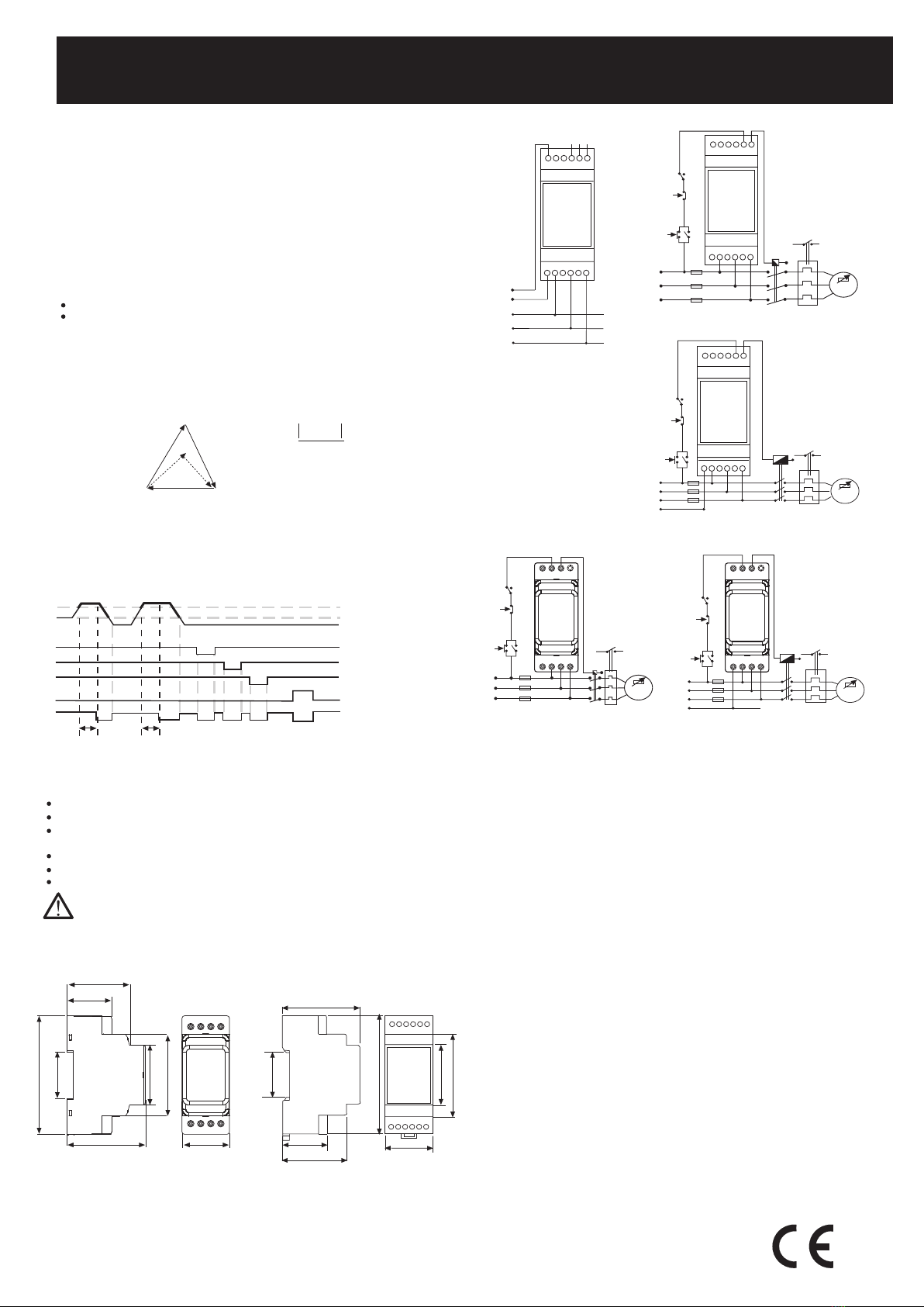
Boyutlar
TiP PK28
48 mm
34 mm
90 mm
35.3 mm
59.7 mm
45.4 mm
61.8 mm
36 mm
TiP PK25
35 mm
90 mm
45 mm
62 mm
58 mm
32 mm
48 mm
35 mm
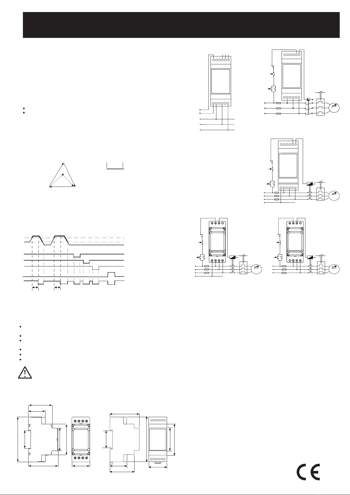
Baðlantý þemalarý Tip PK-25
Tip PK-28
Vin (L-L)
L1 L2 L3
L1
L2
L3
Un
123
A1
A2
A2
A1
NC C NO
(0.5 A, 125 V AC)
MKC-03L
Güvenli Kullaným ve Kurulum Ýçin Uyarýlar
Aþaðýdaki talimatlara uyulmamasý halinde yaralanma veya ölümle
sonuçlanabilecek durumlar ortaya çýkabilir.
Cihaz üzerindeki herhangi bir iþlemden önce tüm besleme gerilimlerini
kesiniz.
Cihaz þebekeye baðlý iken ön paneli çýkarmayýnýz.
Cihazý solvent veya benzeri maddelerle temizlemeyiniz. Cihazý temizlemek
için sadece kuru bez kullanýnýz.
Cihazý çalýþtýrmadan önce baðlantýlarýnýn doðru olduðunu kontrol ediniz.
Cihazý panoya monte ediniz.
Cihazýnýzdaki herhangi bir sorunda yetkili satýcýnýzla temas kurunuz.
Yukarýdaki önlemlerin uygulanmamasý sonucu doðabilecek
istenmeyen durumlardan üretici firma hiç bir þekilde sorumlu
tutulamaz.
MKC-04A
C1
T1
Stop
T1
N
M
3 ~
Start
L1
L2
L3
C1
L1 L2 L3
1 2 3
C1
T1
Stop
T1
N
M
3 ~
Start
L1
L2
L3
N
C1
L1 L2 L3
MKC-03A
1 2 3
N
VL31 VL12
VRef
VRef = 380 VAC
x 100
Asimetri % = -
VL12
VL31
VL31 VL12
VL23
C1
T1
Stop
T1
N
M
3 ~
Start
L1
L2
L3
N
C1
321
N L1 L2 L3
MKC-03A
123
L1 L2 L3
L1
L2
L3
Sistem
N
T1
M
3 ~
MKC-04A
T1
Stop
Start
C1
General
One of the common faults faced in industrial plants is over-heating and burning of
3 phase motors due to the phase failure. Thermic-magnetic device which is an
essential element in motor protection is generally too slow due to both its electro-
mechanical structure and the use of high current setting range to assure demarrage
without tripping. Being designed to eliminate the above disadvantages, MKC-03A
(with neutral connection ), MKC-04A (without neutral connection) Phase Failure
Devices react within 0.2 seconds (fixed) against the following faults and take the
motor out of service.
PHASE FAILURE and PHASE SEQUENCE DEVICES
MKC-03A, MKC-03L, MKC-04A
A4946 / Rev.2
Dimensions
PRECAUTIONS FOR INSTALLATION AND SAFE USE
Failure to follow those instructions will result in death or serious injury.
Disconnect all power before working on equipment.
When the device is connected to the network, do not remove the front panel.
Do not try to clean the device with solvent or the like. Only clean the device
with a dried cloth.
Verify correct terminal connections when wiring.
Electrical equipment should be serviced only by your compedent seller.
Mount device to the panel.
Technical Data
Rated Voltage (Un) :
Please look at labels on the device.
:
3 phase and neutral 220-230 VAC
4 wire star connection (for MK-03/03P, MKC-03/03A/03P)
: 3 phase 380 VAC
3 wire delta connection (for MK-04/04P, MKC-04/04A/04P, MKC-03L)
: 3 phase 220 V AC
3 wire delta connection (for MKC-04/04P)
Auxiliary Supply Voltage : 190-260 V AC (for only MKC-03L)
Operating Range : (0.9-1.1) x Un
Rated Frequency : 50/60 Hz
Output Contacts : 1C/O with 8A, 250 VAC, 2000 VA, Cosj=1
1 C/O with 0.5A, 125 V AC, 62.5 VA,
Cosj=1
(for only MKC-03L)
Warning LEDs : LED Output, normally ON (OFF for any fault)
*LED PTC turns ON when motor winding temperature exceeds 110 oC
Tripping Time : 0.2 s
Ambient Temperature :-5 °C to +50 °C
Protection Class : IP 20
Dimensions : Type PK 25 (
MKC-03A, MKC-03L, MKC-04A)
Type PK 28 (MKC-03A, MKC-04A)
Installation : Surface mounting or on the
mounting rails
Weight : 0.2 kg
Terminal Cable Crosssections: (for PK-28)
4
mm²
(12AWG) solid conductor
6
mm²
(10AWG) stranded rigid conductor
2x2.5
mm²
(14AWG) solid conductor
(for PK-25)
4
mm²
(12AWG) solid conductor
2,5
mm²
(14AWG) stranded rigid conductor
2x1,5
mm²
(2x16AWG) solid conductor
Function Diagram
Fixed unbalance value
Hysterisis
L1
L2
L3
Output Relay
TD= Tripping time
TD
TD
Wrong Phase sequence
2. Phase Sequence
When the phase sequence is correct (L1, L2, L3 in clockwise direction) the output
relay is activated; however, if the sequence is changed by any reason, the output
relay switches OFF immediately.
The voltage asymmetry causes the rise in motor temperature and a reduction of
the rated motor power.
1. Voltage Unbalance (Not Adjustable)
MK-04 includes no neutral connection.
When the neutral-phase voltage unbalance is greater than 40% (fixed), the output
relay is activated and switched OFF the motor. Devices that have fixed voltage
unbalance between 5%-15% can be producted for special order.
Unbalanced voltage may occured when;
The mains are loaded with unbalanced distribution,
One of the 3-phase of motor has lost. In this case, some amount of voltage which
produced by other phases will be inducted on the lost phase. Amount of this value
depends on both the motor type and amount of load.
Output relay is activated when a phase has lost or an unbalanced phase-neutral
value, which is occured with any reason, is smaller than the Asymetrical value which
is defined for the device. If this unbalanced voltage exceeds the adjusted Asymetrical
value, output will release itself and motor will be Switched-off.
In Applications; a proper device must be used regarding to the inducted voltage
value in two-phase which are remained after the other one has lost.
No responsibility is assured by the manufacturer or any of its subsidiaries
for any consequences arising out of the use of this material.
TYPE PK28
48 mm
34 mm
90 mm
35.3 mm
59.7 mm
45.4 mm
61.8 mm
36 mm
TYPE PK25
35 mm
90 mm
45 mm
62 mm
58 mm
32 mm
48 mm
35 mm
Connection Diagrams PK-25
Connection Diagrams PK-28
Vin (L-L)
L1 L2 L3
L1
L2
L3
Un
123
A1
A2
A2
A1
NC C NO
(0.5 A, 125 V AC)
MKC-03L
L1
L2
L3
L1 L2 L3
Sistem
N
MKC-04A
1 2 3
T1
M
3 ~
C1
T1
Stop
T1
N
M
3 ~
Start
L1
L2
L3
N
C1
L1 L2 L3
MKC-03A
1 2 3
N
T1
Stop
Start
C1
C1
T1
Stop
T1
N
M
3 ~
Start
L1
L2
L3
N
C1
321
N L1 L2 L3
MKC-03A
123
L1 L2 L3
L1
L2
L3
System
N
T1
M
3 ~
MKC-04A
T1
Stop
Start
C1
VRef
VRef = 380 VAC
x 100
asymmetry % = -
VL12
VL31
VL31 VL12
VL23
This manual suits for next models
2
Table of contents
Languages:
Other Entes Relay manuals


