Entes DTR-10 User manual

ASTRONOMIC RELAY (DTR-10)
ASTRONOMIC PHOTOCELL RELAY (DTR-14)
MENUS :
Go to previous menu.
Go to next menu.
Scrolling between menus or decrease related value.
Pushing this button 3 seconds on DTR-1 s main menu,
C1 relay position will be changed manually.
Selecting Lock Mode at DTR-14, C1 relay will be on/off on
main menu.
Scrolling between menus or increase related value.
Pushing this button 3 seconds on DTR-1 s main menu,
C2 relay position will be changed manually.
Selecting Lock Mode at DTR-14, C2 relay will be on/off on
main menu.
ESC button
SET button
DOWN button
UP button
:
:
:
:
Sa ety Precautions
If below precautions are not properly observed and carried out, it can
cause to physical accident or damage to the device and installation.
Disconnect power before working on the device.
When device is connected to the network, do not remove the front panel.
Do not clean the device with solvent or similar items. Only clean with
dried cloth.
Verify correct terminal connections before operate the device.
Connect the device to the electrical panel.
Electrical equipment should be serviced only by your competent seller.
No responsibility is assured by the manu acturer or any o its
subsidiaries or any consequences rising out o the use o this
material.
DTR-1 /14 which has a real time clock, is an electronic timer that calculate
the sunset and sunrise periods automatically. It designed for controlling
the devices which are connected to its contacts according to sunset,
sunrise and the time periods which are proggrammed by the user.
DTR-14 has also a photocell option in addition to above features.
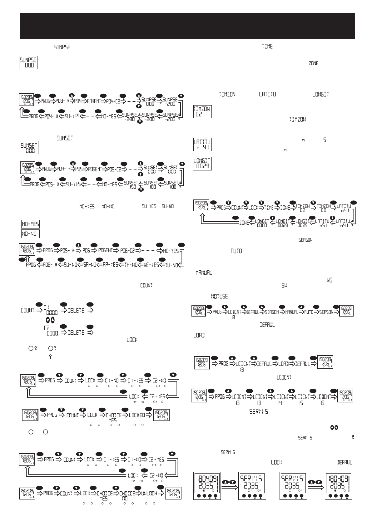
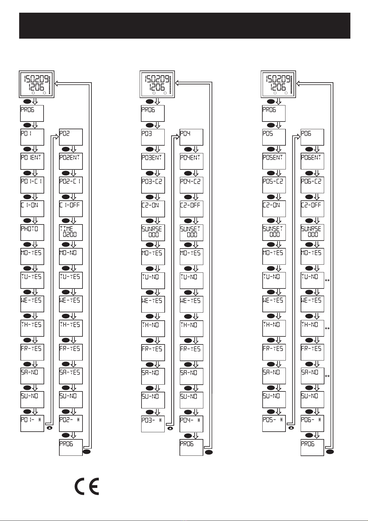
1 ) PROGRAM (PROG) :
In this menu, program settings can be done. Only one unction ON or
OFF can be assigned to each program. Only one o TIME, SUNRISE
or SUNSET unctions can be selected (assigned) or this unction. The
day and/or days o active can be selected separately or this program.
4 different program assigned in order to make eaiser the using of device
by switch it ON at sunset time and switch OFF at sunrise time. These
programs which are assigned as default, can be deleted or changed by
the user.
1.3) C1 / C2 relay selection ( / ): C1 or C2 relay can
be selected via P 1-C1 or P 1-C2. 2 different loads can be controlled
with different functions in this way.
1.4) ON/OFF selection ( / ) / ( / ) : In this
menu, it is selected that whether selected C1 or C2 relay will switch on or
switch off.
1.5) Function selection ( / / / ) : Function
selection is done in this menu. 1 function can be selected for each program.
4 functions exist: Photo, time, sunset and sunrise.
(PHOTO unction
available only or DTR-14)
In order to use the photocell function, photocell sensor and auxiliary
supply always must be connected.
(Available only or DTR-14)
The loads connected to the C1/C2 relays do not unction i auxiliary
supply is o . Even relay status can be mentioned as on ( ve
/veya ), but auxiliary supply is a must or the unctionality.
If the auxiliary supply does not exist, device passes to sleep mode
and display disappears. However, real time clock and related functions
continue to operate. If 4 buttons are pressed at the same time, main menu
displays and so user can see or change all settings.
1
C1 relay can be switched off at all weekdays via photocell function by
using P 2 program.
As above example, relay will switch on at 18: PM for all weekdays via
time function.
NOTE : Device calculates the sunrise and sunset times automatically
according to the summer/winter time and coordinate information which are
set by user.
Device can switch on&off once per day via photocell function. Device can
not switch on/off more than once.
1.5.1) ( )
When photocell sensor perceives the light, ( ) symbol lights.
If lights do not exist, this symbol does not light.
C1 relay can be switched on at all weekdays via photocell function by
using P 1 program.
As above example, if photocell sensor perceives the darkness, after 1
seconds, photocell symbol ( ) does not light on the main menu and the
relay switches on within 1 minute.
As above example, if photocell sensor detects the daylight, after 1
seconds, photocell detected symbol ( ) lights on the main menu and the
relay switches off within 1 minute.
NOTE: Device can only switch on between 12: AM and 24: PM. Device
can not switch on except this time interval.
NOTE: Device only can switch off between 24: PM and 12: AM. Device
can not switch off except this time interval.
1.5.2) ( ) Selected relay can be switched on/off at defined
time period.
SET SET
SET SET
ESC SETSET
SET
ESC
SET
SET
SET
SET
Main Display
SU
C2:
C1:
00
02
04
06
08
10
12
14
16
22
20
18
24
When programmed or in program menu, related
relays are programmed as ON. Relay contact position looks like
on the figure at left side. Relay contacts seem at monitor as
or .
When programmed or in program menu, related
relays are programmed as ON. Relay contact position looks like
on the figure at left side. Relay contacts seem at monitor as
or .
CR-2 32 reserve battery should only be changed by authorized service.
For long time reserve, battery CR-2 32 is used. The shelf life of this
battery is 5 years, if the device is continously voltage supplied. If the device
is not continously voltage supplied and waited in the shelf, the life of the
battery is 2-3 years (changes according to humidity of the shelf).
There are two reserves in the device. Programmed data is protected
by these reserve against power failure.
If power fails for 6-1 hours, programmed data is protected by super
capacitor and device continues to its operation. During this time battery
(CR2 32) is not used; so battery life extends.
For short time, super capacitor is used:
SET SET SET SET
SET
ESC SETSET
SET
ESC
SET
SET SET SET
Main Display
SU
C2:
C1:
00
02
04
06
08
10
12
14
16
22
20
18
24
MANUEL USING :
Using DTR-1 s relay on manuel mode, display must be on main menu.
Pushing DOWN ( ) button during 3 seconds C1 relay; pushing UP ( )
button during 3 seconds C2 relay; After 3 seconds releasing this button
related relays position will change. If relays at ON position it will be OFF,
at OFF position it will be ON. Lock Mode selection does not affect this
application (For details please look at LOCK MODE section).
Using DTR-14s relay on manuel mode, Lock Mode must be selected. On
main menu Lock sign ( ) must be displayed. Changing C1 relay position
use Down ( ) button, for C2 relay use UP ( ) button.
Note: Push same button or returning previous position o relay.
C2:
C1:
00
02
04
06
08
10
12
14
16
22
20
18
24
MO WE FR SA SUTHTU
ESC SET
Day
Date
Time
Relay on/off situation
Lock Mode
ESC button
SET button
UP button
DOWN button
Photocell symbol
It represents the time
interval which relays will
switch ON.
(Available only or DTR-14)
SET SET
SET SET
ESC SETSET
SET
ESC
SETSET
SETSET
Main Display
SU
C2:
C1:
00
02
04
06
08
10
12
14
16
22
20
18
24
C1, C2
C1, C2
1.2) Enter / Delete settings ( / ) : is used to
set a new program or to change the existing program. is used
to delete the existing program.
1.1) Program selection ( ): Device has 16 different programs.
User can assign 1 function to any program between P 1-P16. Only 1 relay
can be selected via one program and also this relay can only be set as
switch on or switch off.
For instance; If the status of C1 relay is set as ON (switch on), 1 program
is used.
In order to switch off the relay which was set as ON before, another
program must be used (Such as 2nd program).
Star sign which exists after the program number ( ) represents that
the program is assigned.
There are 15 di erent program choices or DTR-10 ( ).
The relay, which is switched on via any program, can not be switched off
by deleting the related program. We can switch off the relay in two ways:
a) Released with manually (for details please look at MANUAL USING
section).
b) Enter the switch off time (OFF) for any relay. Delete the program after
the relay switched it off (OFF).
Related steps are mentioned as below:
ASTRONOMIC RELAY (DTR-10)
ASTRONOMIC PHOTOCELL RELAY (DTR-14)
2
As above example, C2 relay will switch on 2 hours 3 minutes before the
sunrise time for all weekdays.
Relay can be controlled before or after the sunrise time according
to the entered time information. This value can be set as hour or
minute. (Max: +9:59, Min: -9:59)
If : is set, relay will be controlled at sunrise time. By this feature,
devices which are connected to the relays, can be controlled after or
before the sunrise time.
1.5.3) ( ) In this menu, sunrise function is enabled however
sunrise time is not set.
SET SET
SET
ESC SETSET
SET
ESC
SETSET
SET
SET
SET
Main Display
SU
C2:
C1:
00
02
04
06
08
10
12
14
16
22
20
18
24
4 ) REAL TIME SETTING ( ) :
Real time and date settings are done in this menu. Year, month, day, hour
and minute can be set respectively.
If YES selected, program function is enabled for related day.
2 ) SWITCH ON & OFF NUMBER o RELAYS ( ) :
In this menu, switch on&off numbers are displayed for C1 and C2 relay
seperately. Device counts once for switching on and once for switching
off.
Count number of C1 or C2 relay can
be reset seperately by selecting
DELETE option.
SET SET SET
SETSET
3 ) LOCK (MANUAL CONTROL) MODE ( ) :
1.6) Day selection ( / , .......... , / ) :
As last, working days for selected programs are set. This setting can be
done for all days starting from Monday.
If NO selected, program function is disabled for related day.
As above example, program function is enabled for Monday, Wednesday
and Friday.
A lock sign ( ) displays near the relay which is locked.
C1 and C2 relays can be locked individually for
DTR-14 and they can be locked together for DTR-1 .
C2:
C1:
SET SET SET
C2:
C1:
C2:
C1:
C2:
C1: C2:
C1:
SET
ESC
C2:
C1:
C2:
C1:
Main Display
SU
C2:
C1:
00
02
04
06
08
10
12
14
16
22
20
18
24
Below diagrams show that how devices can be locked; above diagram
is or DTR-14, below is or DTR-10.
When LOCK mode is disabled, device continues to work by
the last program.
C2:
C1:
SET SET
Main Display
SU
C2:
C1:
00
02
04
06
08
10
12
14
16
22
20
18
24
SET
ESC
Main Display
SU
C2:
C1:
00
02
04
06
08
10
12
14
16
22
20
18
24
C2:
C1:
C2:
C1:
C2:
C1:
Sunset settings are similar with sunrise settings.
1.5.4) ( ) In this menu, sunset function is selected.
As above example, C2 relay will switch off 1 hour 5 minutes before the
sunset time for all weekdays.
SET SET
SET
ESC SETSET
SET
ESC
SETSET
SET
SET
SET
Main Display
SU
C2:
C1:
00
02
04
06
08
10
12
14
16
22
20
18
24
SET
SET SET
SET
ESC SETSET
SET
SET SET
SET
ESC SET
SET
SET
Main Display
SU
C2:
C1:
00
02
04
06
08
10
12
14
16
22
20
18
24
C2:
C1:
00
02
04
06
08
10
12
14
16
22
20
18
24
SA
ESC SET
C2:
C1:
00
02
04
06
08
10
12
14
16
22
20
18
24
SA
ESC SET
C2:
C1:
00
02
04
06
08
10
12
14
16
22
20
18
24
SA
ESC SET
C2:
C1:
00
02
04
06
08
10
12
14
16
22
20
18
24
SA
ESC SET
9 ) SERVICE MODE ( ):
This mode is valid only or DTR-10 and lets the user control and maintain
in urgent situations. In order to choose service mode, lock mode shouldnt
be selected before. In the main menu, up and down buttons ( ) should
be pressed at the same time. When this mode is selected, assigned
programs can not change the relay position. and lock signs ( )
are displayed. In order to exit the service mode, up and down buttons
should be pressed at the same time. Date information will be displayed
instead of . Lock sign will be removed. In case of escaping the
service mode, the last program continues its execution. For user safety,
it is not possible to enter to lock ( ) and factory settings ( )
modes, when service mode is activated.
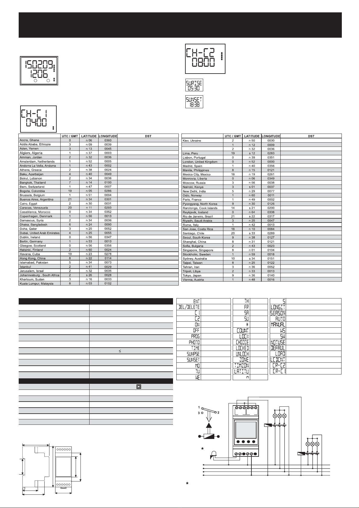
5 ) GEOGRAPHICAL LOCATION SETTING ( ) :
Values which are mentioned in Table-1 are calculated before. Therefore,
there is no need to calculate these values again.
Time difference (UTC/GMT) according to the Greenwich, London
is set. This value is ' 2' for Turkey. Negative time differences
must be subtracted from '24'. For example, time difference for
Mexico City is '-6' hours and so value must be set as
'18'. (24-6=18)
Geographical location, which device will be used in, can be set in this
menu.
For related settings, please refer to Table-1.
If some missing or inaccurate data is entered, wrong sunrise and sunset
times are calculated.
Time zone ( ), latitude ( ) and longitude ( ) submenus
exist in this menu.
Latitude value is set in this menu. North ( )/South ( ) hemisphere
is selected and related degree value is set.
(For example, Istanbul, North ( ) 41°.
6 ) SUMMER / WINTER TIME SETTING ( ) :
In this menu, summer/winter time settings are done.
7 ) FACTORY SETTING ( ) :
8 ) LCD CONTRAST SETTING ( ) :
LCD contrast value can be set between ' -15' by user.
6.1) If Auto ( ) menu is selected, last sunday of March 2. AM
and last Sunday of October 3. AM are loaded. For Turkey and Europe,
automic mode is in use.
6.3) If summer/winter time application does not exist in the related
region, option must be selected.
In this menu, all settings are reset except hour and date. By selecting
option, all programs are reset, counters are reset, relays, which are
switched on, are switched off, lock mode is disabled. Coordinates are
programmed according to Istanbul, season is set as auto and LCD contrast
value is set as '13'.
6.2) Date and hour also can be set by user manually via manual
( ) menu.
First, month, day, hour and minute is set for summer tariff ( ) and then
same settings are done for winter tariff ( ).
Longitude value is set in this menu. If the longitude is east,
degree value is set directly. If the longitude is west, degree value
is subtracted from 36 ° and then entered. (For example, Istanbul,
East (e) 29°).
For instance, longitude value is 99° west for Mexico City and so longitude
value must be set as '261'. (36 -99=261)
Values which are mentioned in Table-1 are calculated before. Therefore,
there is no need to calculate these values again.
The programming of geographical zone for London is mentioned above.
SET SET
SET
ESC SET
SET SET
SET
Main Display
SU
C2:
C1:
00
02
04
06
08
10
12
14
16
22
20
18
24
SET SET SET ESC
Main Display
SU
C2:
C1:
00
02
04
06
08
10
12
14
16
22
20
18
24
Main Display
SU
C2:
C1:
00
02
04
06
08
10
12
14
16
22
20
18
24
SET SET SET ESC
Main Display
SU
C2:
C1:
00
02
04
06
08
10
12
14
16
22
20
18
24
Main Display
SU
C2:
C1:
00
02
04
06
08
10
12
14
16
22
20
18
24
SET SET SET ESC
Main Display
SU
C2:
C1:
00
02
04
06
08
10
12
14
16
22
20
18
24
Main Display
SU
C2:
C1:
00
02
04
06
08
10
12
14
16
22
20
18
24
SET SET SET
C2:
C1:
SET
ESC
C2:
C1:
Main Display
SU
C2:
C1:
00
02
04
06
08
10
12
14
16
22
20
18
24
C2:
C1:
C2:
C1: C2:
C1:
C2:
C1:
Below diagrams show that how LOCK menu can be disabled; above
diagram is or DTR-14, below is or DTR-10.
SET SET
Main Display
SU
C2:
C1:
00
02
04
06
08
10
12
14
16
22
20
18
24
SET
ESC
Main Display
SU
C2:
C1:
00
02
04
06
08
10
12
14
16
22
20
18
24
C2:
C1: C2:
C1: C2:
C1: C2:
C1:
Displays can be observed by pressing ESC button.
DISPLAYS :
Settings, which are done in the 'menus' section, can be observed in this
section. It is not possible to set any parameter in this section.
On the main menu, dashes, which exist near the
numbers between ' -24', represent total working time
of C1 and C2 relay.
3
SU
C2:
C1:
00
02
04
06
08
10
12
14
16
22
20
18
24
This display represents working time (cronogram) of
C1 relay and also working time internal which relay
will operate. As this example, C1 relay will switch on
for 4 hours between 18-22.
00
02
04
06
08
10
12
14
16
22
20
18
24
Regarding to assign programs, dashs which are next to the numbers of
- 24, represent for switch on and switch off time of the relays. Each
dash represents two hours.
ASTRONOMIC RELAY (DTR-10)
ASTRONOMIC PHOTOCELL RELAY (DTR-14)
DIMENSIONS
CONNECTION DIAGRAM
L1
A1A2
Photocell
N
L2
L3
Un
C1 C2
312
312
Available only or DTR-14
Addional Reserv Time 6-1 hours
Program Number
2 Years
Program Reserv Time
16
Please, look at the lateral label.
Display
Accuracy
Power Consumption
Light Power ( or DTR-14)
Sensor ( or DTR-14)
Mechanical Features
Equipment Protection Class
Ambient Temperature
Degree of Protection
Installation
Dimension
Weight
Quantity in 1 carton
Refresh Time
Output Contact
Operating Range (Auxiliary Supply)
Operating Voltage (Un)
Electrical Features
1,3 LCD
1 sec. /Day
< 3 VA
1-3 lux
CdS (Photocell Resistor)
6 sec.
2 Output Contacts / 8 A, 2 VA
Please, look at the lateral label.
Class II ( )
-5°C, +5 °C
IP2
Rail Mounted
PK25
,2 kg
5 pcs
TECHNICAL FEATURES
Note: Di erent operating voltages are available upon request.
Please noti y voltage with the order.
Tablo-2 : Menu abbreviations.
Lagos, Nigeria
Lefkosa, Cyprus
29-03-2009, 03:00 / 25-10-2009, 04:00
No kno n DST
29-03-2009, 03:00 / 25-10-2009, 04:00
No kno n DST
29-03-2009, 01:00 / 25-10-2009, 02:00
29-03-2009, 01:00 / 25-10-2009, 02:00
29-03-2009, 02:00 / 25-10-2009, 03:00
No kno n DST
05-04-2009, 02:00 / 25-11-2009, 02:00
No kno n DST
29-03-2009, 02:00 / 25-10-2009, 03:00
No kno n DST
No kno n DST
29-03-2009, 02:00 / 25-10-2009, 03:00
29-03-2009, 02:00 / 25-10-2009, 03:00
No kno n DST
No kno n DST
No kno n DST
15-02-2009, 00:00 / 18-10-2009, 00:00
No kno n DST
29-03-2009, 02:00 / 25-10-2009, 03:00
No kno n DST
15-03-2009, 00:00 / 11-10-2009, 00:00
No kno n DST
No kno n DST
29-03-2009, 03:00 / 25-10-2009, 04:00
No kno n DST
29-03-2009, 02:00 / 25-10-2009, 03:00
05-04-2009, 03:00 / 04-10-2009, 02:00
No kno n DST
22-03-2009, 00:00 / 22-10-2009, 00:00
No kno n DST
No kno n DST
29-03-2009, 02:00 / 25-10-2009, 03:00
Tablo-1 : Geographical locations in the world.
No kno n DST
No kno n DST
No kno n DST
No kno n DST
27-03-2009, 00:00 / 30-10-2009, 01:00
29-03-2009, 02:00 / 25-10-2009, 03:00
29-03-2009, 02:00 / 25-10-2009, 03:00
29-03-2009, 03:00 / 25-10-2009, 04:00
29-03-2009, 04:00 / 25-10-2009, 05:00
29-03-2009, 00:00 / 25-10-2009, 00:00
No kno n DST
29-03-2009, 02:00 / 25-10-2009, 03:00
No kno n DST
29-03-2009, 02:00 / 25-10-2009, 03:00
15-03-2009, 00:00 / 18-10-2009, 00:00
24-04-2009, 00:00 / 25-10-2009, 00:00
No kno n DST
No kno n DST
29-03-2009, 02:00 / 25-10-2009, 03:00
03-04-2009, 00:00 / 01-11-2009, 00:00
No kno n DST
No kno n DST
No kno n DST
29-03-2009, 01:00 / 25-10-2009, 02:00
29-03-2009, 02:00 / 25-10-2009, 03:00
29-03-2009, 01:00 / 25-10-2009, 02:00
29-03-2009, 03:00 / 25-10-2009, 04:00
15-03-2009, 00:00 / 25-10-2009, 01:00
No kno n DST
No kno n DST
29-03-2009, 03:00 / 25-10-2009, 04:00
27-03-2009, 02:00 / 27-10-2009, 02:00
No kno n DST
No kno n DST
No kno n DST
This display represents the sunrise time which is calculated
according to coordinate, season and real time settings. According
to this example, sunrise time is 5:3 AM
This display represents the sunset time which is calculated
according to coordinate, season and real time settings. According
to this example, sunset time is 18:38 PM.
As above example, C2 relay will switch on for 8 hours.
As the left side example, 8: shows the duration
of how long C2 relay will be switched on. If switch on
time is set 5: 1 instead of 4: , 4- 6 interval
does not have any dashes and also working time
becomes 6:59 instead of 8: .
00
02
04
06
08
10
12
14
16
22
20
18
24
Photocell
Time (Date, hour)
Sunrise
Sunset
Monday
Tuesday
Enter
Delete
1st Relay
2nd Relay
Program
On
Off
Lock
(Manual)
Coordinate
Latitude
North
Selected
Wednesday
Thursday
Friday
Saturday
Sunday
Counter
South
Time difference
Choice
Locked
Unlock
Longitude
Not use
Factory Settings
LCD contranst
Load
Season
Automatic
Manual
Winter / Summer interval
Winter / Summer interval
Cronogram (switch on & off time) of C2 relay
Cronogram (switch on & off time) of C1 relay
TYPE PK25
35 mm
90 mm
45 mm
62 mm
58 mm
32 mm
48 mm
35 mm
ASTRONOMIC RELAY (DTR-10)
ASTRONOMIC PHOTOCELL RELAY (DTR-14)
A2407 / Rev.5
Wrong application : This relay will switch
on at sunset timeand will switch off at
sunrise time.
Example 2: This relay will switch on at
sunrise time and will switch off at sunset
time.
Example 1: This relay will switch on via
photocell sensor and will switch off on
2: AM.
SU
C2:
C1:
00
02
04
06
08
10
12
14
16
22
20
18
24
ESC
SET
SET
SET
SET
SET
SET
SET
SET
SET
SET
SET
SET
SET
SET SET
SET
SET
SET
SET
SET
SET
SET
SET
SET
SET
SET
ESC
In this application, there is a mistake at P 6
program when, switch off time settings are
done for weekdays. Relays will switch off
according to the sunrise time and so
program settings are wrong for Tuesday,
Thursday and Saturday.
ESC
SU
C2:
C1:
00
02
04
06
08
10
12
14
16
22
20
18
24
SET
SET
SET
SET
SET
SET
SET
SET
SET
SET
SET
SET
SET
SET SET
SET
SET
SET
SET
SET
SET
SET
SET
SET
SET
SET
ESC
SU
C2:
C1:
00
02
04
06
08
10
12
14
16
22
20
18
24
ESC
SET
SET
SET
SET
SET
SET
SET
SET
SET
SET
SET
SET
SET
SET SET
SET
SET
SET
SET
SET
SET
SET
SET
SET
SET
SET
ESC
4
This illustration is available or DTR-14.
Other manuals for DTR-10
1
This manual suits for next models
1
Other Entes Relay manuals


Popular Relay manuals by other brands

Rockwell Automation
Rockwell Automation Allen-Bradley Guardmaster MSR55P installation instructions

Ghisalba
Ghisalba GH44B operating instructions

GE
GE IBCG51E21 instructions

Eaton
Eaton DILH1200/22 Instruction leaflet

Simplex
Simplex 4090-9118 installation instructions

Plejd
Plejd DIM-01-2P installation manual


