manuals.online logo
Brands
  1. Home
  2. •
  3. Brands
  4. •
  5. Eonon
  6. •
  7. Car Receiver
  8. •
  9. Eonon D1001 User manual

Eonon D1001 User manual

Other Eonon Car Receiver manuals

Eonon D1002 User manual

Eonon

Eonon D1002 User manual

Eonon D2206 User manual

Eonon

Eonon D2206 User manual

Eonon E0820 User manual

Eonon

Eonon E0820 User manual

Eonon G1306 User manual

Eonon

Eonon G1306 User manual

Eonon E0822 User manual

Eonon

Eonon E0822 User manual

Eonon E033 User manual

Eonon

Eonon E033 User manual

Eonon G2225 User manual

Eonon

Eonon G2225 User manual

Eonon E0823 User manual

Eonon

Eonon E0823 User manual

Eonon G2226 User manual

Eonon

Eonon G2226 User manual

Eonon G2203 User manual

Eonon

Eonon G2203 User manual

Eonon D1301 User manual

Eonon

Eonon D1301 User manual

Eonon X20 User manual

Eonon

Eonon X20 User manual

Eonon G2213D User manual

Eonon

Eonon G2213D User manual

Eonon G2201 User manual

Eonon

Eonon G2201 User manual

Eonon D1203 User manual

Eonon

Eonon D1203 User manual

Eonon E646 User manual

Eonon

Eonon E646 User manual

Eonon G1306D User manual

Eonon

Eonon G1306D User manual

Eonon E1095 User manual

Eonon

Eonon E1095 User manual

Eonon D1303 User manual

Eonon

Eonon D1303 User manual

Eonon D1202 User manual

Eonon

Eonon D1202 User manual

Eonon D1003 User manual

Eonon

Eonon D1003 User manual

Eonon G2216 User manual

Eonon

Eonon G2216 User manual

Eonon G1301 User manual

Eonon

Eonon G1301 User manual

Popular Car Receiver manuals by other brands

Linear Series LS5050 Operation and installation manual

Linear Series

Linear Series LS5050 Operation and installation manual

Kenwood KRC-160 instruction manual

Kenwood

Kenwood KRC-160 instruction manual

Sony XR-CA430X Service manual

Sony

Sony XR-CA430X Service manual

T+A Elektroakustik K1 CD-RECEIVER operating instructions

T+A Elektroakustik

T+A Elektroakustik K1 CD-RECEIVER operating instructions

SoundMax SM-CDM1052 instruction manual

SoundMax

SoundMax SM-CDM1052 instruction manual

Xtrons HD107HD user manual

Xtrons

Xtrons HD107HD user manual

Mopar RB3 manual

Mopar

Mopar RB3 manual

Clarion ADDZEST DMZ615 owner's manual

Clarion

Clarion ADDZEST DMZ615 owner's manual

Sony XAV-601BT Specifications

Sony

Sony XAV-601BT Specifications

PIE GM12-POD/S Operation manual

PIE

PIE GM12-POD/S Operation manual

Hyundai H-910H instruction manual

Hyundai

Hyundai H-910H instruction manual

Sony XR-C6100 Service manual

Sony

Sony XR-C6100 Service manual

Sony CDX-L600X - Fm/am Compact Disc Player Installation/connections

Sony

Sony CDX-L600X - Fm/am Compact Disc Player Installation/connections

Motorola VWA63 Service manual

Motorola

Motorola VWA63 Service manual

Sound Storm STM93R user manual

Sound Storm

Sound Storm STM93R user manual

Nextar D3201 instruction manual

Nextar

Nextar D3201 instruction manual

Alpine CDE-163BT owner's manual

Alpine

Alpine CDE-163BT owner's manual

Kenwood KDC-X303 quick start guide

Kenwood

Kenwood KDC-X303 quick start guide

manuals.online logo
manuals.online logoBrands
  • About & Mission
  • Contact us
  • Privacy Policy
  • Terms and Conditions

Copyright 2025 Manuals.Online. All Rights Reserved.

Model: D1001
WELCOME !
Dear customer,
Thank you for you purchasing the EONON D1001 In-Car DVD/MP3/CD player with AM/FM
radio and USB/SD/MMC memroy card interface and front panel A/V Auxiliary input.
It has been designed, engineered and manufactured to bring you the highest level of
performance and quality, and will give you years of listening pleasure.
WARNING !
When Driving
• Do not watch the video program or operate this car DVD player while driving.
• Keep the volume level Iow enough to be aware of the road and traffic conditions.
When Washing your Vehicle
• Do not expose the product to water or excessive moisture. Moisture can cause electrical
shorts, fire or other damage.
When Parked
• Parking in direct sunlight can produce very high temperatures inside your vehicle. Give the
interior a chance to cool down before starting playback.
Use the Proper Power Supply
• This product is designed to operate with a 12 volt DC negative ground battery system.
Protect the Disc Mechanism
• Avoid inserting any foreign objects into the disc slot. Misuse may cause malfunction or
permanent damage due to the precise mechanism of this unit.
THIS DEVICE IS A CLASS 1 LASER PRODUCT.
The device has a safety system that prevents dangerous laser rays from escaping from the
device during normal use. In order to avoid injury to the eyes, never interfere with or damage
the unit's security system.
The invisible laser beam which could cause hazardous radiation if open or the
interlocks defeated. Do not open covers and do not repair by yourself to avoid
exposure to beam directly.
CLASS 1 LASER
PRODUCT
All packaging and packaging materials that are no longer required should be
recycled.
At the end of its life, you should need to dispose of this product, please note that
the waste electrical product should not be disposed of with household waste.
Check with your local authority or retailer for recycling advice.
01
Content
Content...........................................................................0 1
Precautions.....................................................................02
Installation.................................................................03-05
Removing,keeping and install the detachable front panel.....05
Location and function of keys............................................06
Location and function of the remote control.........................07
General operations......................................................08-12
Radio operations.........................................................12-14
RDS (Radio data system) operations.............................14-15
Media playing basic operations.....................................16-17
Media playing advanced operations..............................17-20
Data disc playing operations...........................................21
USB operations................................................................21
SD/MMC operations........................................................22
External AUX AV input device operations............................22
Setup.........................................................................23-27
System setup.....................................................23-24
Language setup.....................................................25
Audio setup............................................................25
Speaker setup...................................................25-26
Digital setup...........................................................27
Basic concepts on DVD player......................................28-29
Truoubleshooting.............................................................30
Electrical connections......................................................31
Specifications..................................................................32
02
Precautions
Head unit
a. To protect traffic safety and to avoid violations of traffic laws, do not watch a video program
or operate the unit in the vehicle driving.
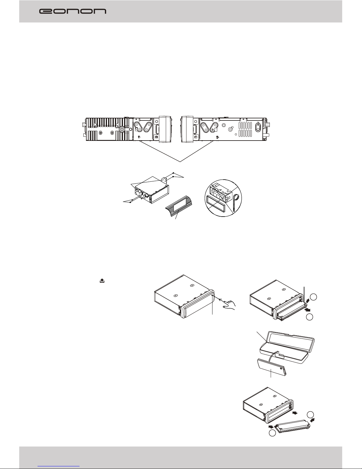
b. In order to ensure safety and normal using, please make the professional to
install this product, do not unauthorized disassembly or repair of the unit avoid damage and
accidents.
c
d This LCD display uses exact electronic structure, do not beat LCD display strong, so as to
avoid damage the product.
e Do not
f
h Do not plug the map card, wiring harness accessories when the unit is powered on, to
avoid damage to the unit or attachment.
We suggest you do not increase the volume of this unit too high, because listening to high
sound over time, it will affect the health of your ears and hearing. At the same time, when you
are driving, if the volume is too high in car can cause you don't hear other vehicles whistle
sound, and other security tips, which affects the safety of drive .
j For using this product safely and correctly, please
a Use 12-cm CDs. Use only conventional, fully circular discs. Do not use shaped discs.
b
d
e
3.
4.
technician
. Do not place this product in a wet environment and water to prevent an electrical shock by
electric shock, damage and fire.
.
. insert any other objects into the disc loader like a coin or pin, etc as this may cause
damage or a short circuit.
. Do not clean the unit with alcohol, only clean with a soft dry cloth; before clean, please turn
off the power supply.
g. Do not expose the unit in direct sunlight for a long time
. un or
i.
. read th manual before using
pecifications and design are
subject to change for further improvement without notice.
Disc
.
. Do not use the dirt, dust, scratches and warping discs in this unit.
c. Do not place stickers or make scratches on discs.
. Do not warp discs.
. A disc should always be kept in its case when not in use to prevent from damage.
f. Do not place discs in the following places:
1. Direct sunlight.
2. Dirty, dusty and damp areas.
Near car heating pipe etc.heat sources.
On the seats or dash board.
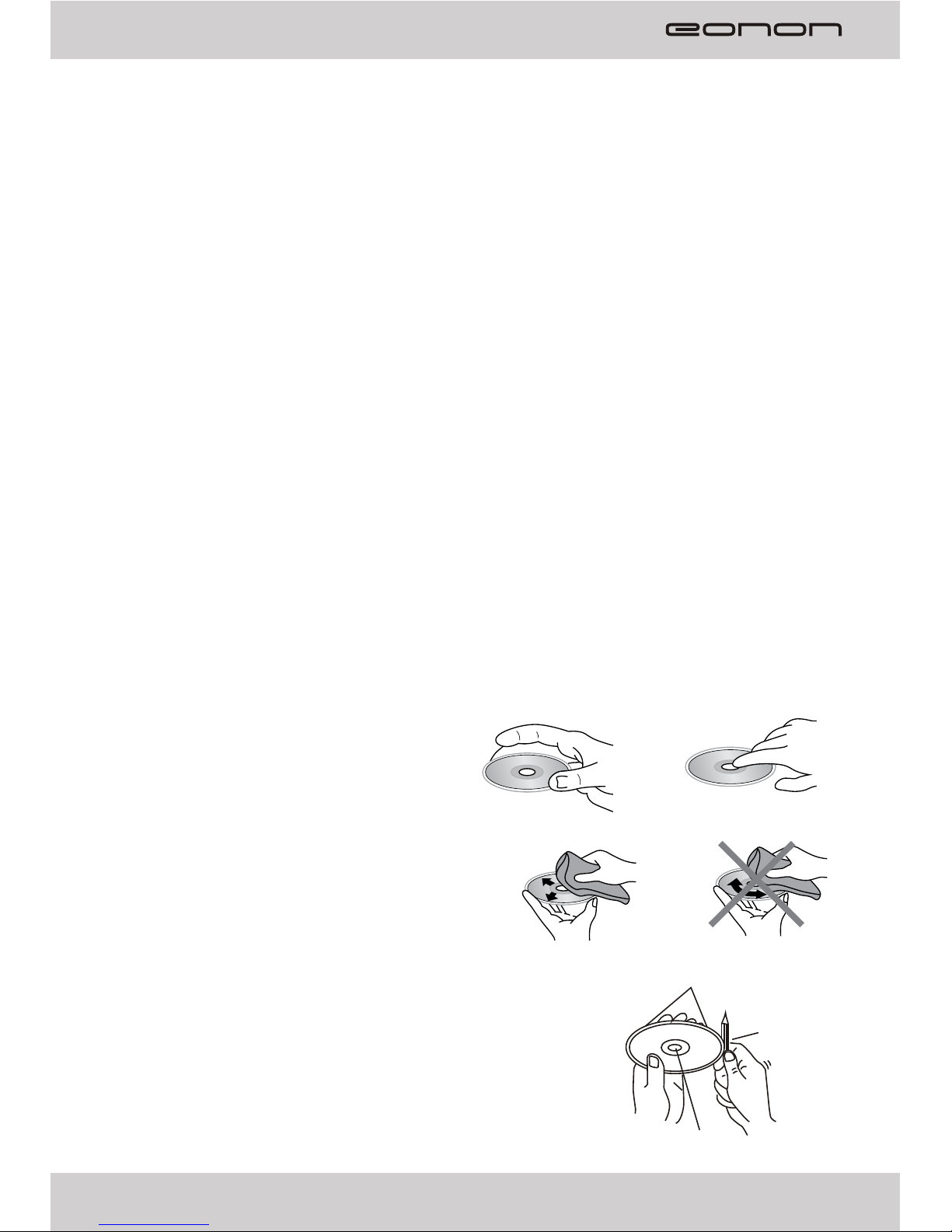
Clean
Use a dry soft cloth to wipe the surface, if the
disc is quite dirty.
Use a soft cloth slightly moistures with isopropyl
(rubbing) alcohol.
Never use solvents such as benzene, thinner or
conventional record cleaners as they may
mar the surface of the disc.
To remove the rough spots on the edges of a new disc
A new disc may have irregularities. It will sometimes be
necessary to remove these rough edges in advance by using
a ballpoint pen or pencil as shown in the illustration.
e carefully
and keep the manual for reference in future.
For we follows a principle of constant improvement, the s
Label side up Do not touch the underside of disc
Wipe the disc from the center toward the outside edge
Rough spots on outside edge
Ball point pen
or pencil
Rough spots on inside edge
Safety precautions:
a. Before installing the unit, disconnect the cable attached to the vehicle battery's negative
(-) terminal. Remove the two screws at the top of the head unit (as shown as the below fig.).
b. Choose the mounting location where the unit will not interfere with the normal drive of the
driver. Install the unit where it does not get in the driver's visual line and it will not get in the
driver's way and cannot injure the passenger if there is a sudden or emergency stop.
Avoid installing the unit where it would be subject to high temperature, such as from direct
sunlight, or from hot air, from the heater, or where it would be subject to dust, dirt or excessive
vibration.
c. The unit may not work properly if is installed at an angle of more than 30° from horizontal.
d. Only use the parts provided with the unit to install it to ensure proper installation.
The unauthorized parts may cause malfunctions.
e. Consult with your nearest dealer if installation requires the drilling of holes or other
modifications of the vehicle.
f. Before finally installing the unit, test the connection and make sure it is all connected up
properly and make the unit is working properly.
DIN Front-Mount / Rear-Mount:
This unit can be properly installed either from 'Front' (conventional DIN Front-mount) or
'Rear' (DIN Rear-mount installation, utilizing threaded screw Holes at the sides of the unit
chassis). For details, refer to the following illustrated installation methods.
1. DIN FRONT-MOUNT (Method A)
This unit can be installed in any dashboard opening with the
following dimensions (DIN standard):
Before installing the unit, test all of the connections and make sure that the unit is working
properly, then follow these steps to install the unit
1 Make sure the ignition is turned off. Disconnect the cable attached to the vehicle battery's
negative (-) terminal.
2. Disconnect the wire harness and the antenna.
3. Press the button to fold down the front panel, then remove the front panel.
4. Lift the top of the outer trim ring, then pull it out to remove it.
5. Use the two supplied release keys supplied to
remove the unit from the mounting bracket.
Insert the left (“L”) and right (“R”) release keys
as far as they will go (with the notches facing
up) into the appropriate slots at the center of
the left and right sides of the unit.
Then slide the unit out of the mounting bracket.
:
.
Installation
03
182 mm
53 mm
Sleeve
Key(L)
Key(R)
Outer trim ring
Front panel
Notch up
6.Fit the mounting bracket by inserting it into the dashboard opening and bend out the tabs
located around the bracket with a screwdriver. Not all tabs will be able to make contact, so
choose the ones which will be most effective with the dashboard.
04
7. Reconnect the wire harness and the antenna, being careful not to pinch any wires or cables.
8. Slide the unit into the sleeve until it locks into place.
9. To further secure the unit, use the supplied metal strap to attach the back of the car radio.
Use the supplied Hex Nut (M5mm) and Spring Washer to attach one end of the strap to the
mounting bolt(M5x 29.3mm) on the back of the unit.
If necessary, bend the metal strap to fit your vehicle's mounting area.
Then use the supplied Tapping Screw (5x25mm) and Plain Washer to attach the other end of
metal strap to a solid metal part of the vehicle under the dashboard.
Note: To install the short threading terminal of the mounting bolt to the back of the unit and the
other long threading terminal to the dashboard.
10.Reconnect the cable to the vehicle battery's negative (-) terminal.
Then replace the outer trim ring and install the unit's front panel.
Removing the unit
1. Make sure the ignition is turned off, and then disconnect the cable attached to the vehicle
battery's negative (-) terminal.
2. Disconnect the wire harness and the antenna,
3. Press the button to fold down the front panel, then remove the front panel.
4. Lift the top of the outer trim ring then pull it out to remove it.
5. Use the two supplied release keys supplied to remove the unit from the mounting bracket.
Insert the left (“L”) and right (“R”) release keys as far as they will go (with the notches facing
up) into the appropriate slots at the center of the left and right sides of the unit.
Then slide the unit out of the mounting bracket.
Sleeve
Tabs
Screwdriver
Dashboard
Mounting bolt
Hex Nut
Spring Washer
Metal strap
Plain Washer
Tapping Screw
2. DIN REAR-MOUNT (Method B)
If your vehicle is a Nissan, Toyota, please follow this mounting instruction to instal it.
If your vehicle is the TOYOTA, please install with the screw holes marked T both sides of the
unit; If your vehicle is the NISSAN, please install with the screw holes marked N both sides
of the unit.
Fixed the unit on the mounting brackets with screws. Align the screw holes on the mounting
bracket with the head unit, then tighten the screws on both sides.
(Note: We will not supply the bracket, if necessary, you can choose to use the original
vehicle mounting bracket, or buy it from the dealer.)
05
5mm MAX
N
TN
T
5mm MAX
N/T
NT
T N
NT
1
2
2
1
Front panel
Front panel
Right hand side of the head unit
Left hand side of the head unit
Choose proper screw holes marked T or N both side of the unit.
Mounting bracket
Screw
Screw
Dashboard or Console
Note:
The outer trim ring, mounting sleeve and the metal strap are not used for installation method
B.
Removing, keeping and install the detachable front panel
Removing the detachable front panel from the head unit
1. Press the OPEN button to flip down
the front panel.
2. Grasp the right side of the front
panel, then gently push the front panel
towards the left side before pulling it out
from the unit.
3.Store the front panel in the protective case provided for safe keeping,
front panel time.if the is not to be used for long
Protective case
Open button
TO ATTACH THE FRONT PANEL
Hold the right side of the front panel with the plate facing down.
First attach the left side of the front panel to the unit by inserting
the hole into the left holder.
Then slightly push it leftwards and attach the right side hole into
the right holder. Finally push up the front panel.
06
24
22
27
25
26
1 2 3
9
10
16 17
5
8
6
11
12
13
18 19
47
15
14 20 21
23
Location and function of keys
When you press the button and the front panel is removed:
Descriptions of Function Controls
(1) Power on/off ( ) Button, MUTE Button
(2) Volume Increase( )/ Decrease( ) Button
(3) BAND(BND) Button, MODE(MOD) Button
(4) DISP Button (System Information Display),
EQ Button
(5) LCD Display
(6) USB port
(7) Open ( ) Button
(8) Preset Station 1, (Play/Pause) Button
(9) Preset Station 2, INT (Intro Scan) Button
(10) Preset Station 3,RPT (Repeat) Button
(11) Preset Station 4, RDM (Random) Button
(12) Preset Station 5, STOP Button
(13) Preset Station 6, GOTO Button
(14) AS/PS (Automatic Search & Preset memory Scan) Button
(15) Button: Tune down, Seek down,
previous track, fast reverse
(16) MENU Button
(17) Button: Tune up, Seek up,
next track, fast forward
(18) IR Remote Control Sensor
(19) PTY(Program Type) Button,
REG(Regional Program) Button
(20) AF(List of Alternative Frequencies),
TA(Traffic Announcement) Button
(21) AUX (Audio/Video auxiliary Input) Jack
(22) SD/MMC Memory Card Slot
(23) Disc slot
(24) Eject Disc ( ) key
(25) Anti-theft LED Indicator
(26) RESET Button
(24) Disc slot Indicator
PTY
MUTE
GOTO
STOP
6
DISP
AF
EQ
TA
1
RDM
VOL
VOL
2
INT
5
4
REG
AUX
D1001
CAR PL AYER 65Wx 4
12
18
14
1
2
3
15
17
27
5
16
4
6
7
8
9
10
11
13
19
20
21
22
23
24
25
26
30
29
28
AF/REG
TA PTY
A
B
07
(1) Power on/off ( ) Button
(2) DISP Button (System Information Display)
(3) A-B Button (Paragraph Repeat)
(4) RPT (Repeat playback) Button
(5) ZOOM(Zoom in /Zoom out) Button
(6) Cursor Buttons ( )
(7) ENTER Button
(8) SETUP Button
(9) Tune down, Seek down, prevous track Button
(10) Tune up, Seek up, next track Button
(11) TITLE( DVD Title Menu) / PBC(Playback Control) Button
(12) (Play/Pause) Button
(13) Preset Station 1~6 Button, Numeric 1~6 Button
(14) TA (Traffic Announcement) Button, Numeric 7 Button
(15) AF(List of Alternative Frequencies) Button,
REG(Regional Program) Button, Numeric 8 Button
(16) Source selector (MODE) Button
(17) AUDIO(Audio language/channel Select) Button
(18) SUB-T(Subtitle Language select/
Playback information select) Button,
(19) MUTE Button
(20) ANGLE(Camera angle selection for some disc) Button
(21) Volume Increase(VOL+)/Decrease(VOL-) Button
(22) MENU Button
(23) Fast Forward Button ( )
(24) Fast Reverse Button ( )
(25) GOTO Button[Search title/chapter/track (VCD/CD)/time],
AS/PS (Automatic Search & Preset memory Scan) Button
(26) Stop Playback Button ( )
(27) PROG(Programmed play mode) , LOC/DX Button
(28) RDM(Random playback) Button, MO/ST Button
(29) Numeric 0 Button, BAND Button
(30) PTY(Program Type) Button, Numeric 9 Button
◄/►,▲/▼
Remark:
♦ Remove the insulating tape before using for the first time.
♦ Point the remote control at the remote sensor within 2 meters.
♦ It may not be possible to operate the remote control if the remote control sensor is
exposed to direct sunlight.
♦ Operation angle: about ±30°in each the direction of the front of the remote sensor.
♦ The remote control is a small, lightweight precision device. To avoid damage, short
battery life, operational errors and poor response.
Please take note of the following points for the remote control:
- Do not subject the remote control to excessive shock.
- Do not put in a trouser pocket.
- Keep away from food, moisture and dirt.
- Do not place in direct sunshine.
Battery replacement
Battery type: a button cell lithium battery (CR2025 3V)
1. Remove the battery holder by pressing the locking
tab with your thumb and pulling it out.
2. Replace the battery with the same type and the (+)
side facing up.
3. Closing the cover : Gently push in the holder until
securely locked into place.
Location and function of the remote control