epredia STP120 Manual

1

2

387718 Issue 16
3
Company Information
© Copyright 2022. Epredia. All rights reserved.
Epredia makes every attempt to ensure that the information contained in this supporting
document is correct and clearly stated, but does not accept responsibility for any errors or
omissions. The development of Epredia products and services is an ongoing process.
Please ensure that any published information you use as a reference is up to date and
relates to the condition of the product. If necessary, check with your local Epredia
representative.
This document may not, in whole or in part, be copied, photocopied, reproduced, translated
or converted to any electronic or other form without prior written consent of Epredia. All
information contained in this manual is proprietary and confidential, and the exclusive
property of Epredia and is protected by copyright.
Contact Addresses
Manufacturer:
Shandon Diagnostics Limited, a subsidiary of Epredia
Tudor Road, Manor Park, Runcorn
Cheshire, WA7 1TA, UK
Tel: +44 (0) 1928 534000
Fax: +44 (0) 1928 534001
Web: www.epredia.com
USA Distributor:
Richard-Allan Scientific LLC, a subsidiary of Epredia
4481 Campus Drive
Kalamazoo, MI 49008, USA
Tel: 1-800-522-7270
Fax: +1 269-372-2674
Web: www.epredia.com
These instruments conform to the general safety and
performance of:
In Vitro Diagnostics Regulation (IVDR) EU 2017/746
Medical Devices Regulations 2002 (SI 2002 No 618, as
amended) (UK MDR 2002)

387718 Issue 16
4
Safety Information
Epredia instruments are designed for convenient and reliable service; however, improper
use or handling by a user may damage the instrument or cause a hazard to health. The
instrument must not be used in a manner not specified by Epredia. Correct maintenance
procedures are essential for consistent performance. It is recommended that users secure a
maintenance contract with our service department.
To remain compliant with regulatory requirements, and to ensure that mandatory safety
upgrades are performed at the earliest opportunity, it is strongly recommended that all
service activities are performed by Epredia-factory trained Engineers. Warranty may be
voided if service is performed by non-factory trained Engineers.
Maintenance or repairs that are not performed by Epredia trained Engineers with proven
training may affect the safety, performance and compliance of the equipment.
Please consult your local sales or support teams for more information about service
contracts
The following sections contain important information for the safe setup and use of
the instrument, and should be read and understood by the user before using the
instrument.
General Safety
This instrument, as supplied, conforms to IEC61010-1 and IEC61010-2-101;
however, the addition of chemicals introduces potential hazards. Good Laboratory
Practice must be employed and consideration must be given to the potential for
hazard when dealing with these chemicals.
Do not use this instrument in close proximity to strong electromagnetic radiation as
these may interfere with the proper operation. The electromagnetic environment
should be evaluated prior to operation of the device.
Good Laboratory Practice must be used when handling tissue samples to prevent
cross contamination and infection. The user should complete a risk assessment to
determine any potential hazards related to tissue handling.
•Do not introduce any source of ignition into, or near, the instrument once it has
been loaded with reagents.
•Do not remove any panels or access covers, unless specifically instructed to do
so. The instrument does not have any user serviceable parts. Potentially lethal
voltages are present inside the instrument.
•The instrument must be properly connected to a good earth (ground) via the
Mains input supply and positioned such that it is possible to interrupt the Mains
supply at the source by removing the plug from the socket.
•Use only factory approved accessories or replacement parts with this
instrument.
387718 Issue 16
5
•Only use reagents recommended in the Operator Guide.
•Disconnect the instrument from the mains supply before performing
maintenance.
•Take necessary precautions when handling glass. Wear Personal Protective
Equipment (PPE) if required.
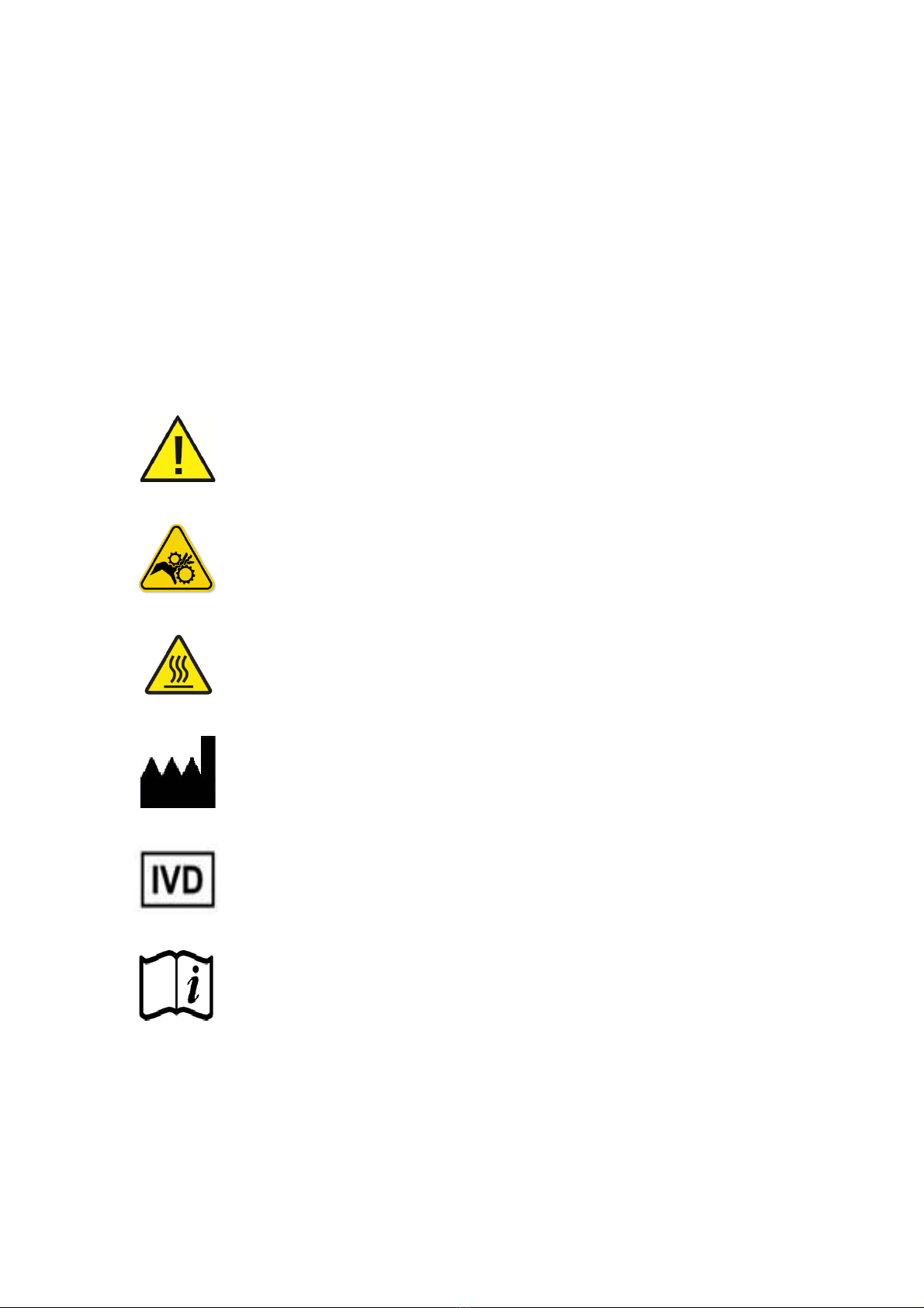
Symbols
The following symbols and conventions may be used throughout this document and on the
instrument:
This symbol is used on the instrument, or in a document, to indicate that
instructions must be followed for safe and correct operation. If this symbol
appears on the instrument, always refer to the operator guide.
This symbol indicates that a surface is hot. If this symbol appears on the
instrument, always refer to the operator guide. Take suitable precautions
This symbol indicates that a surface is hot. If this symbol appears on the
instrument, always refer to the operator guide. Take suitable precautions.
Manufacturer.
This symbol indicates the instrument is an in vitro diagnostic medical device.
This symbol is used on the instrument, or in the document to indicate that
instructions for use must be consulted

387718 Issue 16
6
Chemical Safety
The introduction of chemicals creates potential hazards. Epredia has adopted the following
position with regard to the subject of volatile chemicals used in laboratories:
•Customers using non-specified chemicals in the instrument do so at their
own risk.
•All chemicals recommended by Epredia have auto-ignition temperatures
considerably above any surface temperature that can be reached during a
single fault failure on the instrument.
•The instrument contains no source of ignition in any areas of the instrument
where chemicals are stored, or are likely to leak into in a single fault
condition.
•The operator is fully aware of the contents of the specification documents
detailing the properties of the chemicals they are using.
•
The operator has carried out any legally required assessment of chemicals
used and is using good laboratory practice.
Environment
This instrument is required to comply with the European Union's Waste Electrical and
Electronic Instrument (WEEE) Directive 2012/19/EU. It is marked with the following symbol:
Epredia has contracts with one or more recycling / disposal companies in each EU Member
State, and this product should be disposed of or recycled through them. For further
information contact your Epredia service representative.

387718 Issue 16
7
Warranty Statement
Epredia is proud of their quality, reliability and after-sales services. We continuously strive to
improve our service to our customers.
Please ask your distributor or Epredia representative about service contracts which can help
maintain your instrument in an optimal operating condition.
Warranty provisions necessarily vary to comply with differences in national and regional
legislation. Specific details can be found in the delivery documentation or from your dealer or
representative.
Please note that your warranty may be invalidated if:
•This instrument is modified in any way, or not used as intended by Epredia.
•Accessories and reagents which have not been approved by Epredia are used.
•The instrument is not operated or maintained in accordance with instructions.
•The installation of the instrument was not conducted by a certified Epredia
representative.
Any serious incident that has occurred in relation to the device shall be
reported to the manufacturer and the competent authority of the Member
State in which the user/or the patient is established.

387718 Issue 16
8
Table of Contents
COMPANY INFORMATION .............................................................................................................. 3
SAFETY INFORMATION .................................................................................................................. 4
GENERAL SAFETY ............................................................................................................................ 4
SYMBOLS ........................................................................................................................................ 5
CHEMICAL SAFETY ........................................................................................................................... 6
ENVIRONMENT................................................................................................................................. 6
WARRANTY STATEMENT ................................................................................................................... 7
TABLE OF CONTENTS .................................................................................................................... 8
CHAPTER 1 - INTRODUCTION TO THE EPREDIA TISSUE PROCESSOR STP120...................... 10
INTENDED PURPOSE:...................................................................................................................... 10
DESCRIPTION OF THE EPREDIA TISSUE PROCESSOR STP120 ............................................................ 10
THEORY OF OPERATION ................................................................................................................. 10
Processing – dehydration, clearing and infiltration .................................................................... 10
TECHNICAL SPECIFICATIONS OF THE STP 120 .................................................................................. 11
CHAPTER 2 - REPLACEMENT AND EMPLACEMENT .................................................................. 13
TRANSPORT AND UNPACKING.......................................................................................................... 13
Emplacement........................................................................................................................... 14
Connection .............................................................................................................................. 15
Main Parts of the STP 120 ....................................................................................................... 17
Connection of the Paraffin Baths.............................................................................................. 18
Placement of the baskets......................................................................................................... 19
CHAPTER 3 - CONTROL PANEL................................................................................................... 20
CONTROL PANEL ........................................................................................................................... 20
CHAPTER 4 - PROGRAMMING...................................................................................................... 22
BASKET CYCLE .............................................................................................................................. 22
ENTERING THE PROGRAM ............................................................................................................... 23
STARTING THE PROGRAM ............................................................................................................... 25
DELAYED START............................................................................................................................ 26
STOPPING THE PROGRAM ............................................................................................................... 26
END OF THE PROGRAM ................................................................................................................... 27
TEMPERATURE DISPLAY ................................................................................................................. 27
END OF PROCESS DISPLAY ............................................................................................................. 27
CHAPTER 5 – INSTRUMENT SETUP............................................................................................. 28
SETUP MENU ................................................................................................................................ 28
CHANGING THE LANGUAGE ............................................................................................................. 30
CHANGING THE DATE AND TIME....................................................................................................... 31
WORKING WITH TWO BASKETS ........................................................................................................ 32
POWER FAILURE ............................................................................................................................ 33
EMERGENCY MOVEMENTS .............................................................................................................. 34

387718 Issue 16
9
CHAPTER 6 - MAINTENANCE ....................................................................................................... 35
CLEANING ..................................................................................................................................... 35
CHANGING THE FILTER ................................................................................................................... 36
REPLACING THE BATTERY ............................................................................................................... 37
ALARMS ........................................................................................................................................ 37
RESETTING THE UNIT ..................................................................................................................... 38
APPENDICES ................................................................................................................................. 39
APPENDIX A-REAGENTS................................................................................................................ 39
APPENDIX B-PROGRAM RECORD SHEET......................................................................................... 40
INDEX ............................................................................................................................................. 41
REVISION CONTROL FOR THIS DOCUMENT............................................................................... 42

387718 Issue 16
10
Chapter 1 - Introduction to the Epredia Tissue
Processor STP120
Intended Purpose:
The Epredia STP120 automated tissue processor is an in vitro diagnostic device, designed to
infiltrate tissue specimens with paraffin in medical, pharmaceutical research laboratories
to allow for subsequent examination and diagnosis by a technologist or pathologist. Only
qualified and trained laboratory personnel may operate the STP120.
The instrument may only be operated within the scope of its intended use as described above
and as per the instructions given in this manual.
Any other use of this instrument is considered as an improper action.
Description of the Epredia Tissue Processor STP120
The STP120 has 12 reagent positions, between which baskets containing tissue samples are
automatically transferred and processed from chemical dehydration to paraffin infiltration.
The instrument is programmable via a membrane keypad and display screen, and can store
up to 10 user configured processing protocols. Variable parameters which can be selected by
the user include; immersion time, reagent temperature and agitation.
The STP120 reduces carryover between reagent positions through centrifugal spinning of the
tissue basket above the last used reagent position.
Theory of Operation
Processing – dehydration, clearing and infiltration
The Epredia STP120 rotary movement transports tissue specimens through a sequence of
reagents to complete the process of removing water from the tissue and replacing it with
paraffin.
Samples are first transferred through progressively more concentrated dehydrants, such as
Ethanol, to remove the water. This is followed by a hydrophobic clearing agent (such as
xylene) to remove the alcohol, and finally molten paraffin which can then infiltrate the cleared
tissue.

387718 Issue 16
11
Technical Specifications of the STP 120
Sizes
Diameter of the carousel 850 mm
Height 500 – 700 mm
Diameter of the turning circle 670 mm
Weight
Including packing
145 kg
Net (fully equipped)
70 kg
Electrical installation
Rated Voltage (±10%) 100-120 V~, 50/60 Hz, 1.7A
220-240 V~, 50/60 Hz, 0.9 A
Fuses 110-120 V: (2 x T4AH 250V)
220-240 V: (2 x T2AH 150V)
Battery
Nickel-Cadmium (12V 600 mA)
Overvoltage category 2
Pollution degree II
Sound pressure < 70 dBA
Capacity
Reagent stations
Number of reagent vessels
10 (9, if 3 are for paraffin.)
Volume per reagent vessel
1.8 L
Baskets for the specimen holders
Number of baskets
1 (option of 2)
Basket capacity
120 specimen holders
Paraffin stations
Number 2 (option of 3)
Volume 1.8 L
Rated Voltage 24 V ~
Rated power per station 100 VA
Temperature range 50 – 70 °C
Hysteresis margin 0.1 – 2 °C
Temperature cut-off
80 °C (± 4 °C)
Thermal protection
Manual reset

387718 Issue 16
12
Programming
Number of programs 10 (selectable)
Programmable infiltration time per
station
from 1 s to 90 h 59 m
Rotation stirring selectable
Vertical shake selectable
Centrifugation
selectable
Centrifugation time selectable
Program start delay selectable without time limit
Environmental conditions
at a max. rel. humidity of 60% without condensation
Temperatures
from + 5 to + 40 °C
Storage temperature range from –20 °C to +50°C
Altitude up to 2000 m M.S.L.
Floor loading requirements
160,0 kg /m
2
For indoor use only
387718 Issue 16
13
Chapter 2 - Replacement and Emplacement
Transport and Unpacking
During transportation the STP 120 should always be kept in an upright position.
Inspect the packaging and the STP 120. If either is damaged or the contents do not match
the supplied packing list, inform your local Epredia representative.
Remove any support or brace holding the machine inside the packing box.
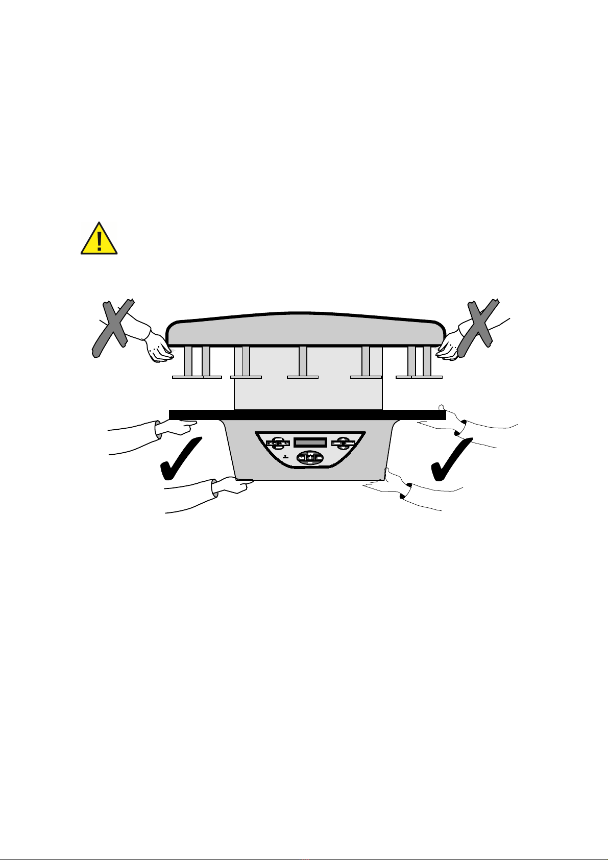
Use safe lifting practices when moving the STP 120. At least two people
are required to move the STP 120. Take care to always hold the STP 120
as shown in fig 1. Never list the STP 120 by the upper cover or the
carousel as this will cause irrepairable damage to the unit.
Fig 1 – Correct Handling of the STP 120

387718 Issue 16
14
Emplacement
Choose a suitable flat surface measuring at least 900 mm in width x 900 m depth with 750
mm of headroom.
It is absolutely necessary that the emplacement of the STP 120 has at
least 750 mm of free headroom otherwise the carousel will be irrepairably
damaged when it opens.
Make sure that:
•The surface is perfectly smooth, flat and stable.
•The site is well ventilated.
•There is sufficient surrounding space to allow easy access while safely supporting
the weight of the machine.
When selecting the emplacement for the machine, remember that the
Main ON/OFF switch is located at the rear and that it must be accessible
at all times
Manual Rotation of the Whole Unit
Apart from the automatic rotating system for the processor cover, the base of the unit is also
fitted with wheels. This enables the whole unit to be turned by hand to enable easy access to
all the reagent vessels and paraffin baths should it be placed close against a wall.
Never turn the unit holding it by the cover.
Before turning the unit, hold it by the reagent vessel support table and proceed as follows:
Use the ↑↓ button, to raise the carousel cover to its uppermost position.
Turn off the unit at the Main ON/OFF switch and unplug the power supply cable (see
next page). This will enable the unit to be turned on its axis without any risk of
damaging the power cable.
387718 Issue 16
15
Connection
The electronic unit of the STP120 is suitably protected and adequately shielded according to
EC Standards on emission and reception of interference. Nevertheless, the unit should not
be installed close to other high power equipment that could generate vibrations or strong
electrical interference.
The STP120 is supplied with a power cable for connection to a standard outlet with earth.
The electrical connection is located at the rear.
Before connecting the power cable, make sure that the STP120 is
adjusted to operate at the supply voltage
Do not replace the detachable mains supply cord with and inadequately rated mains supply
cord.
Initial Turn-On
Before assembling the baths, start the unit to raise the carousel.
Never attempt to turn, raise or lower the carrousel cover by hand or force
it in any way!
Always use the keys on the control panel to make any manual
movements and keep hands away from any moving parts.
Connect the power supply cable and start the STP 120 using the stop-start switch located at
the rear of the unit, above the plug for the power supply cable.
When the power is connected, the STP 120 automatically begins a machine test cycle and
the fume exhaust fan will being operating.
This message appears on the display
(V1.XX indicates the software version).
SPIN TISSUE
PROCESSOR V1.XX
This is followed by:
FILTER CHANGE XXXX HOURS (Refer
to 'Changing the Filter), and then:
C10 C11 C12
16º 16º 16°
This indicates the temperature of the
paraffin baths.
Note
These messages may appear in a language other than your own. If you want to change the
language now, refer to section Changing the Language. Furthermore, the date and time
perhaps do not coincide with those in your country. If you want to adjust the time, refer to
chapter Changing the Date and Time section.

387718 Issue 16
16
The display indicates (in the pre-set
language), a message like the one shown
here.
01/01
READY
12:50
Press the ↑ ↓ button once. Note that the
carousel opens to a half-way position and
the basket holder begins to turn.
When the carousel stops opening, press
the ↑ ↓ key once again to continue
opening the basket holder as far as
possible. The screen will display the
message indicating 'Take sample' and the
reagent vessel located at 'C01'.
TAKE SAMPLE
C 011
If the basket holder is not physically in the position of reagent vessel 1, press the key ↑ ↓
repeatedly to advance the basket to the position of reagent vessel No 1. Disconnect the unit
from the power supply.
Now you can place the reagent vessels and paraffin baths in position.
Connect the paraffin baths.
Before connecting or disconnecting the paraffin baths, make sure that
the unit is disconnected from the power supply by turning off the main
switch located at the rear of the unit.
Now you can turn the unit on again.
387718 Issue 16
17
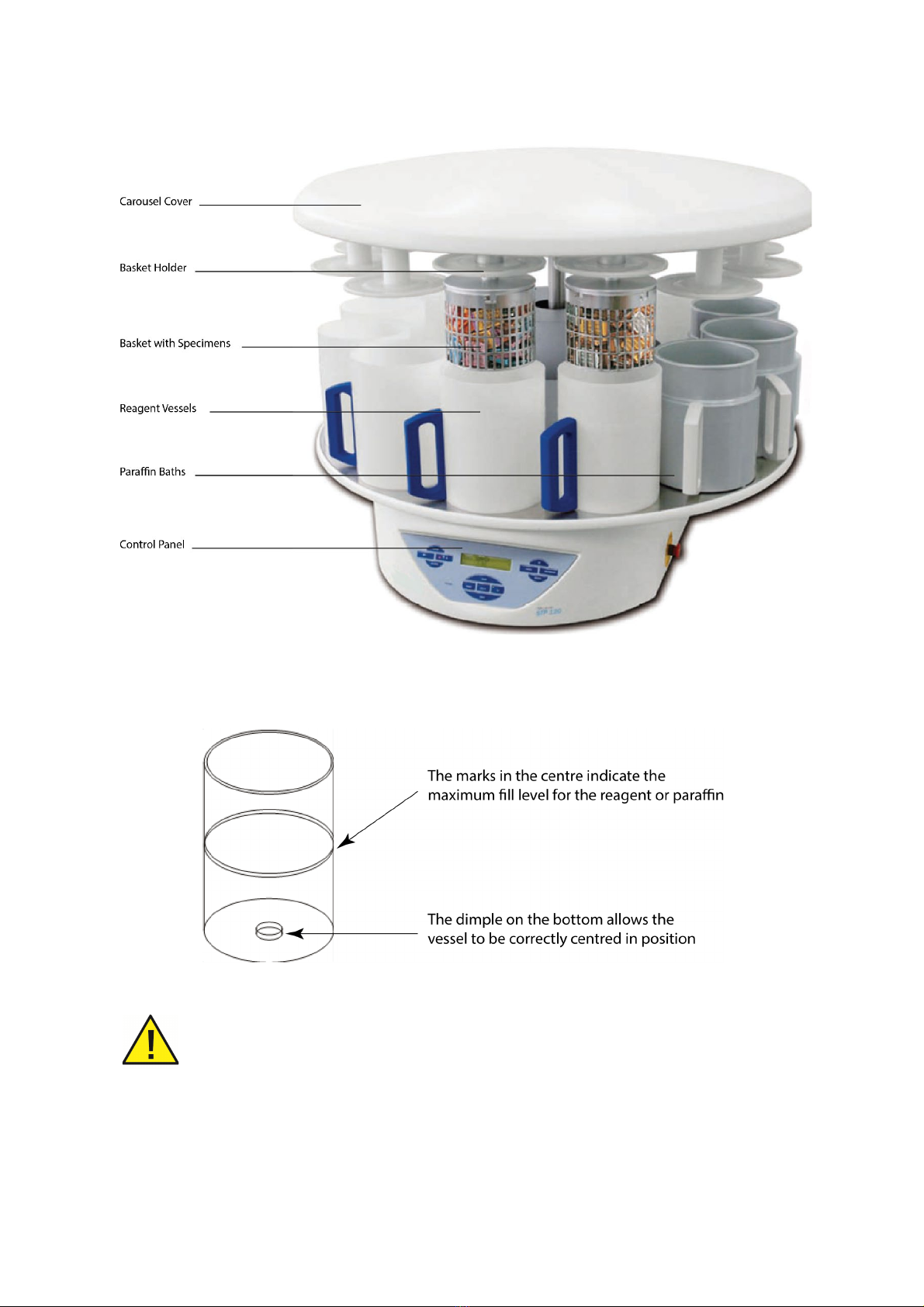
Main Parts of the STP 120
Fig 2 – Main Parts of the STP 120
The model shown in the figure 2 corresponds to the version with two basket holders, three
paraffin baths and reagent vessels.
Fig 3
Under no circumstances should the maximum fill level be exceeded as
the process will not be performed correctly and reagent or paraffin could
be spilled.

387718 Issue 16
18
Connection of the Paraffin Baths
The paraffin baths are connected from the rear of the STP 120.
Before connecting or disconnecting the paraffin baths, make sure that
the STP 120 is disconnected from the power supply by turning off the
main switch located at the rear of the unit.
Always use the following connections:
•The connection marked with the
number 10 only if a third paraffin
bath has been installed in position
10.
•The connection marked with the
number 11 only if the paraffin bath
has been installed in position 11.
•The connection marked with the
number 12 only if the paraffin bath
has been installed in position 12.
Note
The grooves in the edge of the processor table to allow connection of the cables to the
paraffin baths.

387718 Issue 16
19
Placement of the baskets
The baskets are held in position by a four
point bayonet connector.
When fitting the baskets, make sure that the
four studs fit into the four grooves on the edge;
turn the basket as far as possible inside the
groove and allow it to rest on the pivots of the
basket holder (see picture on the right).
Before beginning to process tissues, you should become familiar with the handling and
programming of the STP120. Design a small test program and perform some manual
movements without any reagents in the vessels or samples in the baskets.

387718 Issue 16
20
Chapter 3 - Control Panel
Control Panel
The control panel at the front of the STP 120 contains all the keys required for handling and
programing. Activate the keys by pressing in the centre of the corresponding icon or
indicator. Do not use sharp objects as they could damage the keyboard.
The actions of the keys:
SHAKE
Vertical shake. Pressing this
key lights the indicator light
and activates the SHAKE
function. This function enables
vertical shaking of the basket
during the stirring process
(refer to Basket Cycle).
START
Key to start the automatic operating
cycle (program). When the STP 120 is
operating in automatic mode, the pilot
beside the key is lit.
UP
When adjusting values it increases
the value displayed, or goes back
to the previous option
←
Press this key to make the
machine perform a partial
rotation, moving the basket
holder to the next station. This
is only possible when the
basket holder is in the upper
position.
STOP
Key to stop the automatic operating
cycle. If this key is pressed the STP
120 indicates for confirmation of
whether the process is to be aborted.
Once the stop is confirmed, the
program is cancelled and the STP 120
must be controlled in manual mode
using the keys ↑↓ and ← to place the
basket holder above the first reagent
vessel. The STOP key also halts any
movement of the machine at any time.
DOWN
When adjusting values it
decreases the value displayed, or
goes to the next option.
↑↓
These keys raise and lower
the basket holder, as required.
If pressed when the basket
holder is moving, it will reverse
the direction. The STOP key
stops all movement
TIMER
Allows delaying the start. Refer to
Delayed Start. When the TIMER is
active the display appears as dimmed
the pilot light of the key is lit
PROGRAM
Use this key to access the mode
for editing programs or making
adjustments.
POWER
The LED lights up to indicate
that the unit is connected to
the power supply.
A flashing LED indicates that
the unit is operating on the
emergency battery (for more
information refer to section
Power Failure).
LOCK
Pressing this key blocks all the keys
on the control panel (to prevent
accidental operation). Restore the key
actions by holding down this key for
more than two seconds.
ENTER
Validates the option or
adjustments made.
x2
This key should always be pressed
when the STP 120 is fitted with a
double basket holder (optional
accessory). For more information,
refer to section Working with two
baskets.
For more information, refer to
Chapter 4 – Programming.
Before executing the first real process with reagents and paraffin,
remember that paraffin can sometimes take a long time to melt. After a
long period of disconnection (for example the first start or after power
This manual suits for next models
3
Table of contents
Other epredia Medical Equipment manuals


Popular Medical Equipment manuals by other brands


Getinge
Getinge Arjohuntleigh Nimbus 3 Professional Instructions for use

Mettler Electronics
Mettler Electronics Sonicator 730 Maintenance manual

Pressalit Care
Pressalit Care R1100 Mounting instruction

Denas MS
Denas MS DENAS-T operating manual

bort medical
bort medical ActiveColor quick guide

AccuVein
AccuVein AV400 user manual


