epredia HM 430 Manual


Company Information
© Copyright 2022. Epredia. All rights reserved.
Epredia makes every attempt to ensure that the information
contained in this supporting document is correct and clearly
stated but
does not accept responsibility for any errors or
omissions. The development of Epredia products and services
is an ongoing pr
ocess. Please ensure that any published
information you use as a reference is up to date and relates to
the condition of the product. If necessary, check with your local
Epredia representative.
This document may not, in whole or in part, be copied,
photoco
pied, reproduced, translated, or converted to any
electronic or other form without prior written consent of Epredia.
All information contained in this manual is proprietary and
confidential, and the exclusive property of Epredia and is
protected by copyright.
These instruments conform to the general safety and
performance of:
•In Vitro Diagnostics Regulation (IVDR) EU 2017/746
Symbols
The following symbols and conventions may be used
throughout this document and on the instrument:
This symbol is used on the equipment, or in a
document, to indicate that instructions must be
followed for safe and correct operation.
This symbol is also used on the instrument, or in a
document, to indicate that irritants or potentially
harmful chemical
s are present. Refer to the Material
Safety Data Sheets for the products, and always use
Good Laboratory Practice.
If this symbol appears on the instrument always refer
to the operator guide.
Contact address
Shandon Diagnostics Limited, a subsidiary of Epredia
Tudor Road, Manor Park, Runcorn
Cheshire, WA7 1TA, UK
Tel: +44 (0) 1928 534000
Fax: +44 (0) 1928 534001
Web: www. epredia.com
This symbol is utilised
on the instrument, or in a
document, to indicate that there are potential
biological risks associated with the instrument and /
or with instrument use. Always use Good Laboratory
Practice.
USA Distributor Cutting hazard, sharp edges, watch your fingers.
Richard-Allan Scientific LLC, a subsidiary of Epredia
4481 Campus Drive
Kalamazoo, MI 49008, USA
Tel: 1-800-522-7270
Fax: +1 269-372-2674
Web: www. epredia.com
Separate taking back of electrical and
electronic
instruments in the countries of the European Union:
This is to be applied in the countries of the European
Union and other European countries with a separate
collecting system within the waste management. This
product, being an electro and/or el
ectronic
instrument, must be treated separately within the
waste management process (WEEE).
A warning is given in the documentation if there is a
potential risk of injury, equipment failure or damage to
the equipment or samples.
Note
Notes give
additional information about a job or
instruction, but do not form part of the instruction.
Manufacturer
This symbol is used on the instrument, or in the
document, to indicate that instructions for use must
be consulted
Serial number
It is stated on the product label sticker.
It is built up as follows: SYYMMXXXXEP
S=Production site, Y=year of production, M=Month of
production, X= Counter, EP=Epredia
So the serial number states the production date of the
device.

HM 430 Operator Guide Issue 03
4
Contents
Company Information 3
Symbols .........................................................3
Contact address .............................................3
USA Distributor ...............................................3
Contents 4
Safety Information 5
General Safety ................................................5
Chemical Safety..............................................6
Environment ...................................................6
Warranty Statement ........................................6
Chapter 1 - Introduction 7
Intended Purpose:...........................................7
Description of Sliding Microtome HM 430.........7
Technical Data Sheet ......................................8
Chapter 2 – Operating Instructions
9
Setting up the Microtome ................................9
Cutting Movement...........................................9
Locking the Sledge .......................................10
Specimen Feed.............................................12
Specimen Clamping......................................16
Changing Specimen Clamps .........................17
Knife Carrier..................................................18
Standard Equipment .....................................21
Additional Equipment (optional)......................21
Chapter 3 – Theory of Operation
23
Specimen Coarse Feed ................................ 23
Specimen Clamping System and Specimen
Orientation ................................................... 23
Knife Carrier................................................. 23
Microtome with Fast Freezing Unit ................ 23
Chapter 4 – Working with the
Microtome 24
Preparation and Orientation .......................... 24
Coarse Feed ................................................ 24
Sectioning Instructions ................................. 24
How to Avoid Malfunctions ........................... 24
Chapter 5 – Maintenance 25
Annual Routine Maintenance......................... 25
Service Contract .......................................... 25
Chapter 6 – Cleaning and Care 26
Cleaning Intervals......................................... 26
Cleaning Agents........................................... 26
Care ............................................................ 26
Appendices 27
Appendix A – Conditions for Transportation of the
Instrument ................................................... 27
Index 29
Revision Control For This
Document 30

HM 430 Operator Guide Issue 03
5
Safety Information
Epredia instruments are designed for convenient and
reliable service; however, improper use or handling
by a user may damage the instrument or cause a
hazard to health. The instrument must not be used
in a manner not specified by Epredia. Correct
maintenance procedures are essential for consistent
performance. It is recommended that users secure a
maintenance contract with our service department.
To remain compliant with regulatory requirements,
and to ensure that mandatory safety upgrades are
performed at the earliest opportunity, it is strongly
recommended that all service activities are
performed by Epredia-factory trained Engineers.
Warranty may be voided if service is performed by
non-factory trained Engineers.
Maintenance or repairs that are not performed by
Epredia trained Engineers with proven training may
affect the safety, performance and compliance of the
equipment.
Please consult your local sales or support teams for
more information about service contracts.
The following sections contain
important information for the safe
setup and use of the instrument and
should be read and understood by
the user before using the instrument.
General Safety
This instrument, as supplie
d, conforms
to IEC 61010-1 and IEC 61010-2-
101;
however, the addition of chemicals
introduces potential hazards. Good
Laboratory Practice must be
employed,
and consideration must be
given to the potential for hazard when
dealing with these chemicals.
Do not use the instrument in close
proximity to strong electromagnetic
radiation, as these may interfere with
the proper operation. The
electromagnetic environment should
be evaluated prior to operation of the
device.
Good Laboratory Practice must be
used when handling tissue samples to
prevent cross contamination and
infection. The user should complete a
risk assessment to determine any
potential hazards related to tissue
handling.
•
Do not introduce any source of
ignition into, or near, the
instrume
nt once it has been
loaded with reagents.
•
Do not remove any panels or
access covers, unless specifically
instructed to do so. The
instrument does not have any user
serviceable parts.
•
Use only factory approved
accessories or replacement parts
within the instrument.
•
Only use reagents recommended
in the operator guide.
HM 430 Operator Guide Issue 03
6
Chemical Safety
The introduction of chemicals creates potential
hazards. Epredia has adopted the following position
with regard to the subject of volatile chemicals used
in laboratories:
•
Customers using non-
specified
chemicals in the instrument, do so at
their own risk.
•
All chemicals recommended by
Epredia have auto-
ignition
tempera
tures considerably above any
surface temperatures that can be
reached during a single fault failure on
the instrument.
•
The instrument contains no source of
ignition in any areas of the instrument
where chemicals are stored, or likely
to leak into, in a single fault condition.
•
The operator is fully aware of the
contents of the specification
documents detailing the properties of
the chemicals they are using.
•
The operator has carried out any
legally required assessment of
chemicals used and is using Good
Laboratory Practice.
Environment
This instrument complies with the European Union's
Waste Electrical and Electronic Equipment (WEEE)
Directive 2012/19 EU. It is marked with the following
symbol:
Epredia has contracts with one or more recycling /
disposal companies in each EU Member State, and
this product and packaging should be disposed of
or recycled through them. For further information
contact your Epredia service representative.
Warranty Statement
Epredia is proud of their quality, reliability and of our
after-sales service. We continuously strive to
improve our service to our customers.
Please ask your distributor or Epredia representative
about service contracts which can help maintain
your instrument in an optimal operating condition.
Warranty provisions necessarily vary to comply with
differences in national and regional legislation.
Specific details can be found in the delivery
documentation or from your dealer or representative.
Please note that your warranty may be invalidated if:
•This instrument is modified in any way, or not
used as intended Epredia.
•Accessories and reagents which have not been
approved by Epredia are used.
•The instrument is not operated or maintained in
accordance with instructions.
•The installation of the instrument was not
conducted by a certified Epredia representative.
Any serious incident that has
occurred in relation to the device
shall be reported to the
manufacturer and the competent
authority of the Member State in
which the user/or the patient is
established.

HM 430 Operator Guide Issue 03
7
Chapter 1 - Introduction
Intended Purpose:
The Epredia sliding microtome HM 430 is an in vitro
diagnostic device, designed to take precision
sections of tissue specimens including the sectioning
of paraffin embedded samples in medical,
pharmaceutical laboratories as necessary
preparation for their examination and subsequent
diagnosis. Only qualified and trained laboratory
personnel may operate the HM 430.
The instrument may only be operated within the
scope of its intended use as described above and as
per the instructions given in this manual.
Any other use of this instrument is considered as an
improper action.
Description of Sliding
Microtome HM 430
The sliding microtome HM 430 from Epredia is a
highly efficient instrument for sectioning paraffin in
routine and research. The main applications are in
human and veterinary medicine. Large and hard
specimens from pharmaceuticals industry or from
quality assurance labs can also be sectioned.
The cross-roller bearings on sledge and block allow
non-tiring working and a smooth sliding movement
with optimal stability.
The HM 430 will cut sections from 1 µm to 60 µm.
The specimen clamping can be moved up and
downwards via the coarse feed wheel with crank
handle on the left side of the instrument. This way,
specimen and knife edge distance can be adjusted
quickly.
The knife carrier is designed so the knives can be
easily clamped in place and adjusted.
The coaxial specimen orientation allows orientation
with one hand.

HM 430 Operator Guide Issue 03
8
Technical Data Sheet
Microtome
Section thickness range 0.5 - 60 µm
Resolution 0.5 µm for 0 ... 5 µm
1 µm for 5...10 µm
2 µm for 10...20 µm
5 µm for 20...60 µm
Vertical feed range max. 40 mm
Horizontal knife stroke max. 190 mm
Cutting drive manual sliding movement
Coarse feed manual via coarse feed wheel
Feed automatic via sliding movement or manual via feed lever
Specimen size up to max. 80 x 60 mm
Specimen orientation x - and y - axes universal 8°
Transportation- & storage conditions:
Storage temperature
range -20°C up to +50°C
Operating conditions:
+5°C up to +35°C
(at a max. rel. humidity of 60%)
for indoor use only
Floor loading requirements: 150 kg/m2
Dimensions wide: 360 mm, deep: 490 mm, high: 320 mm
Weight 23 kg

HM 430 Operator Guide Issue 03
9
Chapter 2 – Operating Instructions
Setting up the Microtome
Note
The kind of the used examination materials and all
special conditions for their processing, pre-
treatment and, if necessary, storage as well as
instrument controls for correct and safe operation is
in the responsibility of the operator. The operator is
also responsible for special equipment and materials
and/or reagents for the operation of the instrument.
•Unpack the microtome and remove the
wrapping.
•To carry the instrument, lift it on the front and rear
side from the lower side.
Do not carry the instrument on the
handle of the knife sledge!
•Place the instrument on an even surface in a way
that the knife guidance is moved towards the
user and away from him.
•The coarse feed wheel should show to the left
side and the knife carrier handle to the right side.
Note
Sectioning can be influenced by nearby instruments
which generate vibrations. For this reason, the
microtome should be placed on a stable and
vibration free table.
The standard equipment includes four rubber feet
which are smaller than the ones that were installed
in our factory. Should the working height be too high
when setting up the microtome, unscrew the original
feet and replace them with the lower ones.
Cutting Movement
•To start the cutting movement of the microtome,
move the sledge horizontally.
•The knife (or blade) which is clamped into the
knife carrier is drawn horizontally over the
specimen towards the user. This way, sections
are produced.
•In the front reversal point of the sliding
movement, i.e. when the sledge is moved again
backwards, the preselected section thickness is
delivered either manually via a lever or
automatically by moving over the advance
position.
•This way, the specimen is moved in vertical
direction towards the knife with the selected
section thickness and a new section can be
made.

HM 430 Operator Guide Issue 03
10
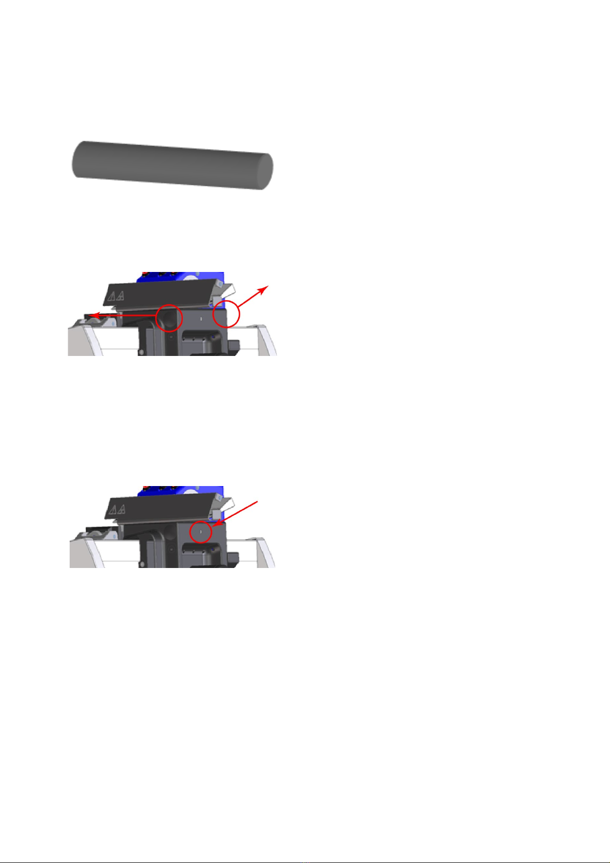
Locking the Sledge
For the protection against injury by unintended
movements of the knife sledge, the microtome is
equipped with a lock of the sledge in any position.
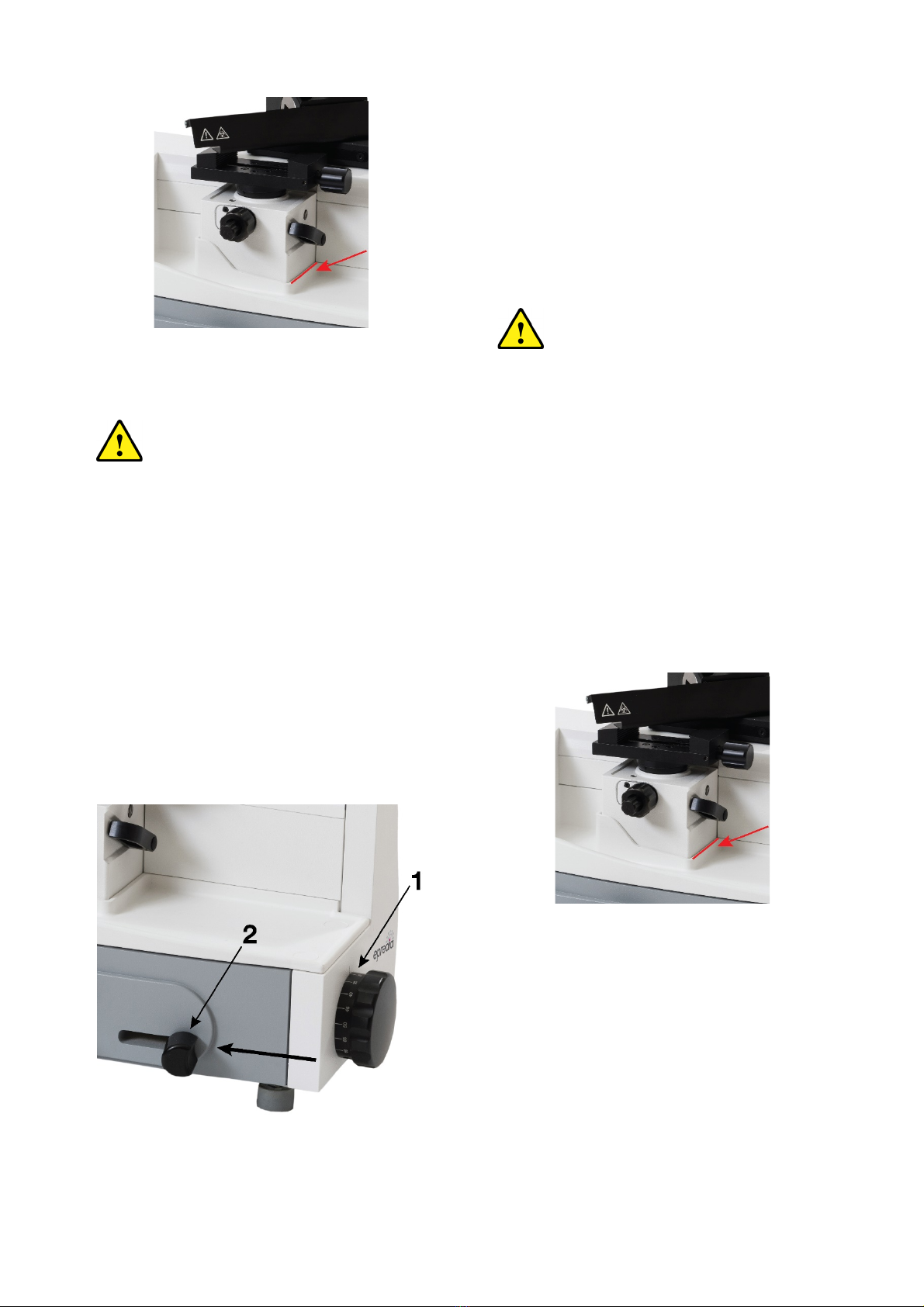
Figure 1
The sledge should be locked for the
user's personal safety, e.g. when new
specimens are clamped into position,
knives are exchanged, the instrument is
cleaned, or other adjustment processes
are carried out.
•The lock is released via a lever on the rear side of
the sledge and is easily accessible from the right
side behind the handle.
Locking the sledge
•Swivel the locking lever from the upper position
(Figure 1.1) into the lower position (Figure 1.2).
•Then the red marked lever surface becomes
visible to show the clamped state (Figure 2).
Figure 2
Loosening the sledge
•Swivel the lever from the lower position (Figure
1.2) into the upper position (Figure 1.1) until the
red mark cannot be seen anymore.
•The knife sledge can be moved again.
HM 430 Operator Guide Issue 03
11
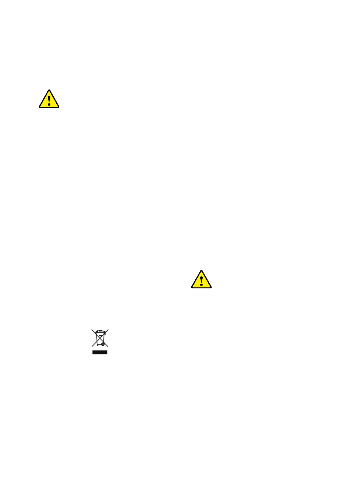
Additional Ballast for Sledge
As required by users to vary the weight of the sledge,
we have included additional ballast (Figure 3) into the
standard equipment.
Figure 3
To assemble the additional ballast, please proceed
as described below:
Figure 4
Remove the two cover caps, located sideways at the
sledge (Figure 4).
Insert the ballast (Figure 3) into the opening and close
it again by using the two cover caps (Figure 4).
Fix the ballast with the laterally set-screw (Figure 5)
Figure 5
To remove the ballast, please execute this procedure
in reverse order.
HM 430 Operator Guide Issue 03
12
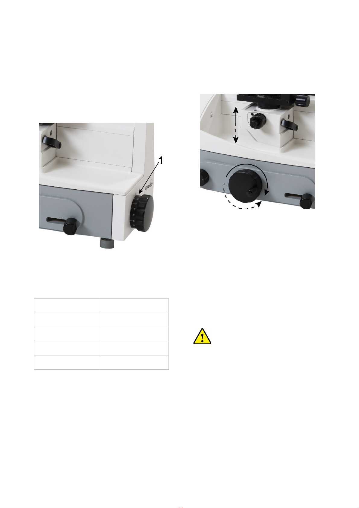
Specimen Feed
Setting Section Thickness
The required section thickness is set by turning the
scaled wheel on the front side of the instrument to
left or right side. The setting is locking and the
currently selected value can be read on the highest
point of the scale opposite the index marking (Figure
6.1).
Figure 6
The graduation of the section thicknesses is divided
into four ranges:
Range
Graduation
from 0.5 µm to 5 µm 0.5 µm
from 5 µm to 10 µm 1 µm
from 10 µm to 20 µm 2 µm
from 20 µm to 60 µm 5 µm
Coarse Feed
For the fast up and downward travel between
specimen and knife edge as well as for trimming, the
microtome has a coarse feed with vertical direction.
Figure 7
•The specimen clamping can be moved 40 mm
vertically up or downwards via the coarse feed
wheel (Figure 7).
•Turn the wheel in a clockwise direction, the
specimen clamping moves upwards towards the
knife.
•Turn the wheel in a counter-clockwise direction,
the specimen moves downwards away from the
knife.
If the specimen clamping is moved
upwards until a red line (Figure 8) can be
seen, the end of the feed range is nearly
achieved. Approx. 3 mm of feed range is
still available.
HM 430 Operator Guide Issue 03
13
Figure 8
Do not cross over this upper end
position by applying more force. Non-
observance leads to damage on the
instrument!!!
Fine Feed, Manual
After having adjusted knife and specimen as well as
having trimmed the specimen, sectioning can be
started.
•The feed of the section thickness which was
preselected on the scaled wheel (Figure 9.1) is
carried out either automatically by moving the
knife sledge over integrated, selectable feed point
or by manually activating the feed device.
•The manual feed is carried out by press the feed
lever (Figure 9.2).
Figure 9
•For this, the knife sledge is moved behind the
specimen and the feed lever is activated once in
the direction of arrow.
•Afterwards pull the knife sledge towards the front
to generate a section.
•Press the feed lever several times, the set section
thickness can be multiplied accordingly.
If a red line (Figure 10) c
an be seen
during sectioning, the end of the feed
range is nearly achieved. Approx. 3 mm
of feed range is still available.
Afterwards, the end of the feed range
can be noticed by a higher force
application on the feed lever.
Do not carry out feed by applying more
force. However, move the specimen
clamping again into a deeper position via
the coarse feed wheel as soon as
possible.
Non-
observance leads to damage on
the instrument!!!
Figure 10
HM 430 Operator Guide Issue 03
14
Fine Feed, Automatic
•The feed of the section thickness which was
preselected on the scaled wheel (Figure 9.1) is
carried out either automatically by moving the
knife sledge over integrated, selectable feed point
or by manually activating the feed device.
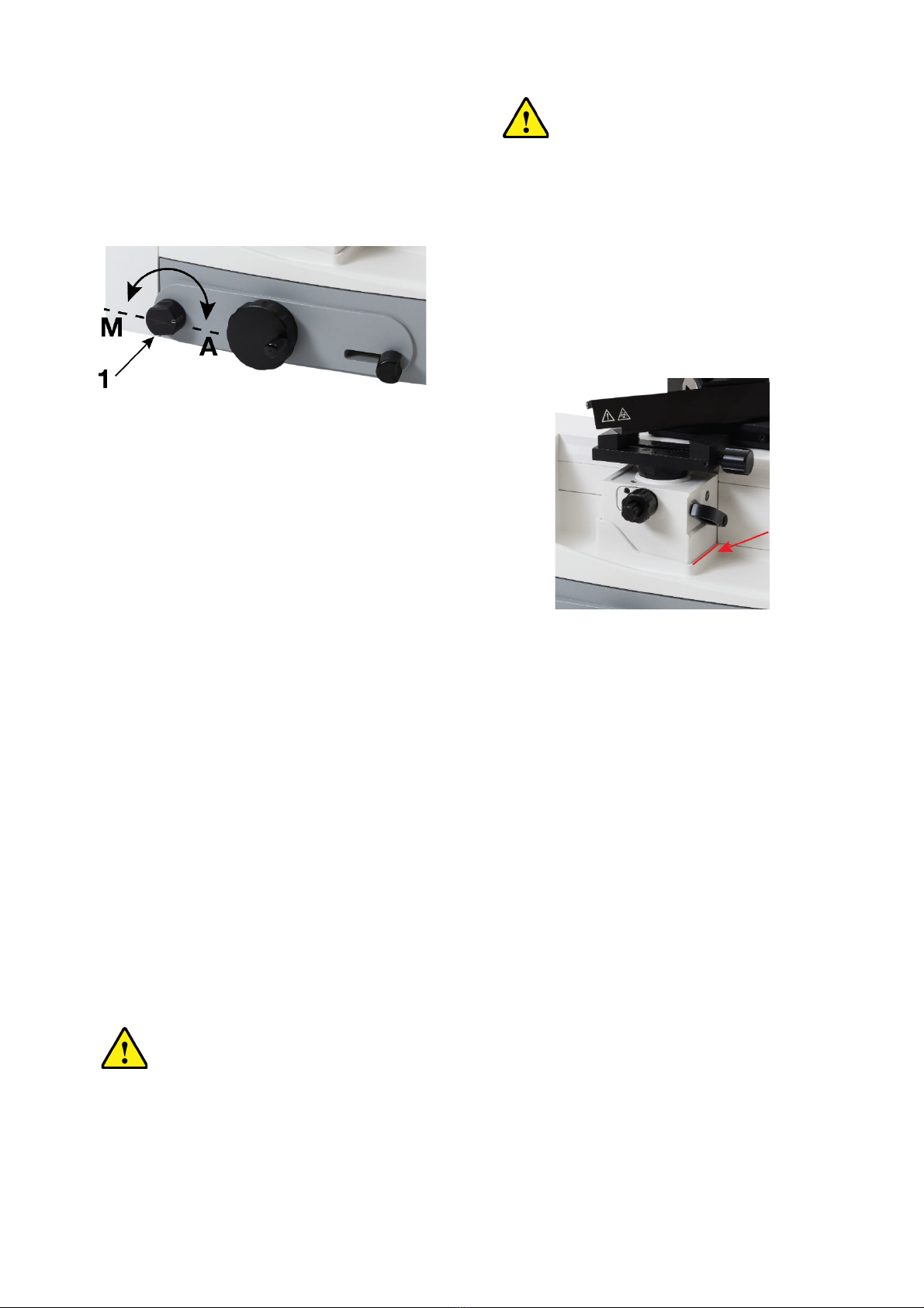
Figure 11
•The automatic feed is carried out by moving the
knife sledge into a selectable position behind the
specimen. This feed process can be noticed by a
slight resistance when moving the knife sledge.
•The automatic feed can easily be turned on and
off.
•For this, turn the turning knob (Figure 11.1)
behind the coarse feed wheel forwards or
backwards to the respective stop.
•When the index mark on the turning knob shows
towards the front and thus visible for the operator
(position Automatic), the automatic feed is turned
on.
•When the index mark shows on the knob shows
towards the rear, the automatic feed is turned off
(position Manual).
Note
For optimal sections, always move the sledge
together with the knife to the rear side over the entire
specimen and then move it forwards.
Turning on and off the automatic
position is not possible when the knife
sledge is in the rear position.
If a red line (Figure 12) is seen during
sectioning, the end of the feed range is
nearly achieved. Approx. 3 mm of feed
range is still available.
Do not apply more force for carrying
out the feed. However, move the
sp
ecimen clamping again into a
deeper position via the coarse feed
wheel as soon as possible.
Non-observance leads to damage on
the instrument!!!
Figure 12

HM 430 Operator Guide Issue 03
15
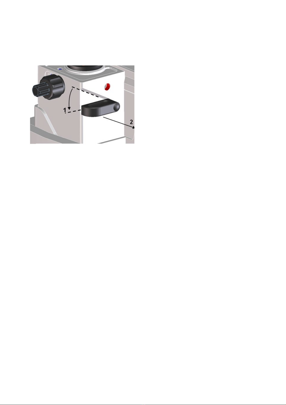
Moving the Automatic Feed Position
The automatic feed is carried out by moving the knife
sledge into a selectable position behind the
specimen.
The knife sledge position, on which the feed of the
preselected section thickness is carried out, can be
chosen within a wide range to accommodate various
specimen sizes. Therefore, it is possible to set the
automatic advance position close behind the
specimen to avoid useless sledge travel distances.
Figure 13
•For this move the knife sledge into the position
where the automatic feed is to be carried out.
•Secure the knife sledge via the locking lever into
position.
•Loosen the clamping lever on the lower side of
the knife sledge and move the entire lever
mechanism forwards and backwards until a slight
resistance can be noticed.
•Tighten the clamping lever again.
•Loosen the sledge lock and move over the
specimen.
•When returning again over the specimen, a feed
is carried out in new selected position.

HM 430 Operator Guide Issue 03
16
Specimen Clamping
To clamp specimens, different specimen clamping
systems are available. With the orienting adapter it is
simple to align the specimen properly in relation to
the knife.
Standard SPECIMEN CLAMP (Cat. no.
715480)
The standard specimen clamp is used for
rectangular and square paraffin blocks.
Figure 14
•Insert the specimen on the front fixed jaw (Figure
14.2) and tighten it via the clamping screw (Figure
14.3) with the movable jaw (Figure 14.1).
For the stability of the specimen, do not
let it project over the clamping jaws too
much!
Standard Specimen Clamp
•This specimen clamp is used in the same way as
the above-described standard specimen clamp
(see cat. no. 715480).
•The clamping screw and thus the clamping
direction of this clamp is arranged transversely in
relation to the sectioning direction.
•Specimens with a size up to 45 x 60 mm can be
inserted.
For the stability of the specimen, do not
let it project over the clamping jaws too
much!
Universal Cassette CLAMP (Cat. no.
715500)
The universal cassette clamp represents a quick-
change system for standardized embedding
cassettes.
Figure 15
•To insert or remove cassettes, press the lever
(Figure 15.1) upwards.
HM 430 Operator Guide Issue 03
17
Changing Specimen Clamps
Due to the quick-change system of the specimen
clamping’s, specimen clamps can be easily and
rapidly changed without needing any tools.
Figure 16
•Loosen the clamping of the specimen clamp
(Figure 16.1).
•Set the specimen clamp horizontally by means of
the set screws of the orientation device.
•To replace the specimen clamp turn the eccentric
lever downwards (Figure 16.1) to the stop and
pull it off (Figure 16.2).
•Now the specimen clamp can be removed and
replaced with another one.
Note
Before inserting another clamp, please note the
position of the hole in the adapter! It must be aligned
in longitudinal direction of the instrument so that the
eccentric lever can be pushed in again.
•Again, push the eccentric lever into the specimen
block.
•Then press the eccentric lever upwards to fix the
specimen clamp in position.

HM 430 Operator Guide Issue 03
18
Knife Carrier
Due to moving parts in connection also
with the microtome knife, a danger area
arises, which might lead to hand injuries
in case of non-
compliance with the
safety features of the microtome and
when disregarding the instruction
manual.
Figure 17
The knife carrier of the microtome is easy to use and
equipped with a knife guard for user safety while
adjusting knife and specimen.
While working on the knife carrier, it
should be locked with the locking device
of the sledge (see part 2-4).
Inserting the knife
•To insert the knife, slightly unscrew the two
clamping screws (Figure 17.1) until the knife can
be pushed in from the side.
•Then tighten the two clamping screws to fix the
knife in its position.
Clearance angle adjustment
The clearance angle between cutting edge and
specimen can be adjusted very easily to the
respective requirements of the tissue to be sectioned
without loosening the clamping of the knife.
•For this, use the two coaxial screws (Figure 17.2
and Figure 17.3) on the upper side of the knife
carrier.
•Loosen the clamping screw (Figure 17.3) in a
counter-clockwise direction and adjust the
clearance angle by means of the set screw
(Figure 17.2).
•The adjusted clearance angle can be read on the
scale which is on the right side of the knife carrier.
•Then tighten the screw Figure 17.3) in a
clockwise direction to fix the clearance angle.
Note
By experience, usable cuts are only achieved at a
clearance angle of 10° or more.

HM 430 Operator Guide Issue 03
19
Protection Against Injury
•The knife carrier is equipped with a knife guard
(Figure 17.4) which should be used while knife or
specimens are adjusted.
Please note that knives with a length of
more than 16 cm (e.g. 22 cm) and/or if
it is clamped too much on one side,
projects over the knife guard resulting in
possible hazards of being injury
although the knife guard is used.
Moving the knife sideways
•If the cutting edge of the knife is blunt, loosen the
clamping screws (Figure 17.1) and move the knife
to the left or right side.
•This process can also be used to protect the
knife, as for trimming and fine sectioning different
parts of the knife can be used.
Diagonal position of the knife
After having loosened the central fastening screw of
the knife carrier (Figure 17.5) via the attached hex
head wrench (size 6), the knife can be adjusted
diagonally according to the tissue to be sectioned.
This is called "angle cut".
However, please note that due to the diagonal
positioning the usable width of the specimen
decreases!
Height adjustment plates (optional)
•In case the height adjustment of the specimen
block is not sufficient for cutting high specimens,
a height adjustment plate can be mounted
between knife carrier and sledge.
•Height adjustment plates are available with 5 mm,
10 mm and 20 mm.
Knife profile
Knives with profile c and d are available. The
opposite figure (Figure 18) shows schematically the
angles on the cutting-edge profiles of c- and d-
knives.
Figure 18

HM 430 Operator Guide Issue 03
20
Blade Holder for Disposable Blades
Two different types of disposable blades are
available: low-profile blades (height: 8 mm) and
high-profile blades (height: 14 mm). When using
disposable blades, a blade holder together with a
disposable blade is clamped into the knife carrier.
Insert the Blade
•Insert the blade holder into the knife carrier from
the left side and tighten the two clamping screws
on the knife carrier.
•The clamping lever on the blade holder can be
positioned in two ways: 0 = loosened, 1 =
clamped.
•To insert the blade, turn the clamping lever to 0
(Figure 19).
•Please note that locating and clamping surfaces
are clean!!
•To clamp the blade, turn the clamping lever to 1.
Clearance angle adjustment
•The clearance angle between blade and
specimen must be adjusted in the same way as
the clearance angle between knife and specimen
is adjusted.
Protection against injury
•The knife carrier of the instrument is equipped
with a knife guard which can be moved sideways.
•This knife guard should be used while knife and
specimen are adjusted.
•This reduces the danger of injury considerably!
Figure 19
This manual suits for next models
3
Table of contents
Other epredia Medical Equipment manuals


