Ericsson BML 161 66/2 Setup guide

ericssonz
Installation/Operator’s
Manual
M-RK
ENHANCED VEHICULAR
CHARGER BML 161 66/2

2
TABLE OF CONTENTS
Page
SAFETY INFORMATION................................................................ 4
SAFE DRIVING RECOMMENDATIONS FOR USERS
OF MOBILE RADIOS RECOMMENDED BY AAA................... 5
OPERATING RULES AND REGULATIONS.................................. 5
OPERATING TIPS............................................................................ 7
INTRODUCTION.............................................................................. 7
OPERATION..................................................................................... 8
MOBILE CHARGER OPERATION.............................................. 8
Enhanced Vehicular Charger....................................................... 8
Enhanced Vehicular Charger
with Remote Control Unit........................................................ 9
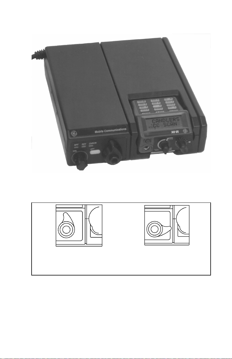
FRONT PANEL SWITCHES AND INDICATORS...................... 10
Enhanced Vehicular Charger....................................................... 11
BATTERY CHARGER DETAILS.................................................... 12
INSTALLATION............................................................................... 13
UNPACKING AND CHECKING THE EQUIPMENT................. 13
Enhanced Charger....................................................................... 13
Enhanced Charger with Remote Control Unit............................. 13
TOOLS REQUIRED ...................................................................... 14
PLANNING THE INSTALLATION ............................................. 14
MOUNTING THE UNIT............................................................... 14
SYSTEM CONFIGURATION....................................................... 15
Accessing The Dip Switches....................................................... 15
Setting the DIP Switches............................................................. 16
Remote Control Operation .......................................................... 17
Radio Configuration.................................................................... 17
INTERCONNECT CABLE............................................................ 17
Power Leads................................................................................ 17
Connecting To A Switched Power Source .................................. 18
Speaker Option ........................................................................... 18
Antenna Connection ................................................................... 18
Other Connections....................................................................... 18
Copyright © February 1996, Ericsson Inc.
This manual is published by Ericsson Inc., without any warranty. Improvements and changes
to this manual necessitated by typographical errors, inaccuracies of current information, or
improvements to programs and/or equipment, may be made by Ericsson Inc., at any time and
without notice. Such changes will be incorporated into new editions of this manual. No part of
this manual may be reproduced or transmitted in any form or by any means, electronic or
mechanical, including photocopying and recording, for any purpose, without the express
written permission of Ericsson Inc.

3
TABLE OF CONTENTS (con’t)
Page
ILLUSTRATIONS
Figure 1 - Enhanced Vehicular Charger .............................................8
Figure 2 - Charger With M-RK II Personal Radio Inserted................ 10
Figure 3 - Universal Device Connector (UDC)
Rotary Latch Knob ...........................................................10
Figure 4 - Mounting The Charger.......................................................15
Figure 5 - Interconnection Diagram For Charger
(Without Control Unit).....................................................19
Figure 6 - Interconnection Diagram for Charger
(With Control Unit) ..........................................................20
Figure 7 - Standard Power Cable........................................................21
Figure 8 - Remote Control Unit Cable................................................22
Figure 9 -Power Cable 19B801358P2................................................23

4
SAFETY INFORMATION
The operator of any mobile radio should be aware of certain hazards
common to the operation of vehicular radio transmissions. A list of several
possible hazards is given:
1. Explosive Atmospheres - Just as it is dangerous to fuel a vehicle with
the motor running, similar hazards exist when operating a mobile radio,
be sure to turn the radio off while fueling the vehicle. Do not carry
containers of fuel in the trunk of the vehicle if the radio is mounted in
the trunk.
2. Interference to Vehicular Electronics Systems - Electronic fuel
injection systems, electronic anti-skid braking systems, electronic cruise
control systems, etc., are typical electronic systems that may
malfunction due to the lack of protection from radio frequency energy
present when transmitting. If the vehicle contains such equipment,
consult the dealer and enlist his aid in determining the expected
performance of electronic circuits when the radio is transmitting.
3. Dynamite Blasting Caps - Dynamite blasting caps may be caused to
explode by operating a radio within 500 feet of the blasting caps.
Always obey the "Turn Off Two-Way Radios" signs posted where
dynamite is being used.
When transporting blasting caps in your vehicle:
a. Carry the blasting caps in a closed metal box with a soft lining.
b. Leave the radio OFF whenever the blasting caps are being put
into or removed from the vehicle.
4. Radio Frequency Energy - To prevent burns or related physical injury
from radio frequency energy, do not operate the transmitter when
anyone outside of the vehicle is within two feet of the antenna.
5. Liquefied Petroleum (LP) Gas Powered Vehicles - Mobile radio
installations in vehicles powered by liquefied petroleum gas with the LP
gas container in the trunk or other sealed-off space within the interior of
the vehicle must conform to the National Fire Protection Association
standard (NFPA) 58 requiring:
a. The space containing the radio equipment shall be isolated by
a seal from the space containing the LP gas container and its
fittings.

5
b. Outside filling connections shall be used for the LP gas
container.
c. The LP gas container shall be vented to the outside of the
vehicle.
SAFE DRIVING RECOMMENDATIONS
FOR USERS OF MOBILE RADIOS
RECOMMENDED BY AAA
•Read the literature on the safe operation of the radio.
•Keep both hands on the steering wheel and the microphone in its
hanger whenever the vehicle is in motion.
•Place calls only when vehicle is stopped.
•When talking from a moving vehicle is unavoidable, drive in the
slower lane. Keep conversations brief.
•If a conversation requires taking notes or complex thought, stop the
vehicle in a safe place and continue the call.
•Whenever using a mobile radio exercise caution.
OPERATING RULES AND REGULATIONS
Two-way FM radio systems must be operated in accordance with the
rules and regulations of the Federal Communications Commission (FCC).
As an operator of two-way radio equipment, you must be thoroughly
familiar with the rules that apply to your particular type of radio operation.
Following these rules helps eliminate confusion, assures the most efficient
use of the existing radio channels, and results in a smoothly functioning
radio network.
When using your two-way radio, remember these rules:
1. It is a violation of FCC rules to interrupt any distress or emergency
message. As your radio operates in much the same way as a
telephone "party line", always listen to make sure that the channel
is clear before transmitting. Emergency calls have priority over all
other messages. If someone is sending an emergency message -
such as reporting a fire or asking for help in an accident - KEEP
OFF THE AIR!

6
2. The use of profane or obscene language is prohibited by Federal
law.
3. It is against the law to send false call letters or false distress or
emergency messages. The FCC requires that you keep
conversations brief and confine them to business. To save time, use
coded messages whenever possible.
5. Using your radio to send personal messages (except in an
emergency) is a violation of FCC rules. You may send only those
messages that are essential for the operation of your business.
6. It is against Federal law to repeat or otherwise make known
anything you overhear on your radio. Conversations between others
sharing your channel must be regarded as confidential.
7. The FCC requires that you identify yourself at certain specific
times by means of your call letters. Refer to the rules that apply to
your particular type of operation for the proper procedure.
8. No changes or adjustments shall be made to the equipment except
by an authorized or certified electronic technician.
IMPORTANT
Under U.S. law, operation of an unlicensed radio transmitter
within the jurisdiction of the United States may be punishable by
a fine of up to $10,000, imprisonment for up to two years, or
both

7
OPERATING TIPS
The following conditions tend to reduce the effective range of two-way
radios and should be avoided whenever possible:
•Operating the radio in areas of low terrain, or while under power
lines or bridges.
•Obstructions such as mountains and buildings.
In areas where transmission or reception is poor, some improvement
may be obtained by insuring that the antenna is vertical. Moving a few yards
in another direction or moving to a higher elevation may also improve
communication.
INTRODUCTION
The M-RK and Enhanced Vehicular Charger BML 161 66/2 unit can be
used with both the M-RK I and M-RK II Personal radios. The following
batteries may be used with the M-RK I or M-RK II radios and these
chargers
19A149838P1 1200 mAh
19A149838P2 1200 mAh (Intrinsically safe)
344A3278P1 1700 mAh
344A3278P2 1700 mAh (Intrinsically safe)
A vehicular charger enhances the operational versatility of an M-RK
radio in the mobile environment. See Table 1 for feature.
The Enhanced Vehicular Charger allows the user to operate the radio
while it is in the charge mode. With the Enhanced Vehicular Charger, the
M-RK portable radio can be used as a mobile radio. In this configuration,
the M-RK radio can be used with an external antenna, microphone, and
speaker. The radio can also be operated with a remote mounted control unit.

8
Table 1 - Vehicular Charger Features
FEATURE ENHANCED
BML 161 66/2
Fast Charge Yes
Charge and Ready Indicator Lights Yes
Transmitter Enabled Indicator Light Yes
Vehicular Repeater Enabled Indicator Light No
10-Watt External Speaker Amplifier with
Volume Control Yes
External Microphone Control Yes
External Antenna Connector Yes
ENHANCED
Figure 1 - Enhanced Vehicular Charger
OPERATION
MOBILE CHARGER OPERATION
There are two different type of mobile chargers.
1) Enhanced Vehicular Charger
2) Enhanced Vehicular Charger with Remote Control Unit
Enhanced Vehicular Charger
To operate the Enhanced Vehicular Charger, place the M-RK radio into
the charger and turn the rotary knob clockwise until it locks into position
(see Figures 2 & 3). The CHRG LED should light to indicate that the
battery is charging. When the battery is fully charged, the CHRG LED will
turn off and the RDY LED will turn on. At this time, the button in the center

9
of the rotary knob may be pressed to unlock the radio from the charger, and
the radio may be removed.
When the radio is in the charger, it may be operated as normal, except that
the separate speaker and microphone must be used.
When the radio is in the charger, it may be operated as
normal, except that the separate speaker and microphone
must be used.
NOTE
Enhanced Vehicular Charger with Remote Control Unit
To operate the Enhanced Vehicular Charger, place the M-RK radio into
the charger and turn the rotary knob clockwise until it locks into position
(see Figure 2 & 3). Turn on power to the control head and then turn on
power to the radio. Microphone must be connected to Control Unit during
this mode of operation.
1) When the radio is in the charger, it may be operated as
normal through the remote control unit. The separate
speaker and microphone must be used.
2) Never insert or remove the radio from the charger unit
by pulling on the antenna, or using it as a handle, as
this may damage the antenna.
3) Volume on charger must be set to 1/4 turn. Audio
volume is controlled by remote control head.
NOTE

10
Figure 2 - Charger With M-RK II Personal Radio Inserted
(Antenna Removed For Photo Only).
UDC Released UDC Engaged
Figure 3 - Universal Device Connector (UDC) Rotary Latch Knob

11
FRONT PANEL SWITCHES AND INDICATORS
Enhanced Vehicular Charger
This front panel contains three indicator lights; TX, RDY, and CHRG,
an ON/OFF volume control switch for operation of the M-RK radio as a
mobile radio, an Option push-button, and the UDC Rotary Latch Knob.
1) Indicator Lights
TX (Red) Lights if the M-RK radio is transmitting
RDY ( Green) Lights if battery is 90 to 100 percent charged and
the charger is in trickle charge mode.
CHRG ( Yellow)Lights when radio is first inserted in the charger.
Indicates that the radio is in charge mode.
2) ON/OFF Volume Control Switch
This switch powers the radio for operation as a mobile radio.
3) Option Push-button
This button can be programmed for many functions, but factory
programming causes the same action as the M-RK "clear"
function. This option is not available during remote control
operation.
4) UDC Rotary Latch Knob
This knob latches the M-RK radio in the charger and connects the
UDC connector to all circuits within the charger to allow the M-RK
radio to operate as a mobile radio. It should always be latched
when the radio is in the charger.

12
BATTERY CHARGER DETAILS
To maximize nickel cadmium battery life, the M-RK vehicular
chargers are designed with automatic controls which limit the
rapid charging of M-RK batteries if the internal battery
temperature is below 0°C (+32°F) or above +45°C (+113°F).
The charger indicates this high or low internal temperature
condition by a yellow LED which blinks at a slow rate.
If a slow blinking, yellow LED is observed, the operator must
wait until the internal battery temperature stabilizes within the
allowable range before restarting the charging procedure by
removing and re-inserting the radio into the charger.
In a vehicular application, with either high ambient temperature
inside or outside of the vehicle, the automatic charging control
will often prevent rapid charging or limit the time of rapid
charging.
In other situations, where the operator inserts and removes the
radio many times during a short period of time, the automatic
control will sense a high internal battery temperature (due to
start-up rapid charging of the battery) and will prevent further
rapid charging of the battery until the internal temperature of the
battery stabilizes within the acceptable range.
NOTE
When the M-RK radio is placed in the charger, the radio's battery pack is
charged. The fast or "rapid" charge feature, normally is applied
immediately, and is controlled by the microprocessor circuits within the
charger. The following details apply to the battery charge feature:
•Normally, when initially placed in the charger, the battery pack is
fast charged and the yellow charge indicator glows continuously
until it is near a full charge (between 90% and 100% full charge).
At this time the charger switches to a slow or "trickle" charge rate
and completes the charge. During the "trickle" charge the green
ready indicator is illuminated.
•If the CHARGE INDICATOR flashes, the battery is not being fast
charged. Several factors may cause this to occur. These include,

13
dirty battery pack contacts, an extremely hot or cold battery pack,
or a defective battery pack.
•Engagement of the UDC is not necessary for battery charge
operation, but is required to operate an M-RK Personal in the
enhanced vehicular charger. The UDC should also be in the
engaged position whenever the vehicle is moving, for both the
standard and enhanced models, to firmly hold the radio in the
charger in case of an accident.
If the Battery is deeply discharged, the radio must be
turned off when inserted into the charger.
NOTE
INSTALLATION
UNPACKING AND CHECKING THE EQUIPMENT
Before starting the installation, carefully unpack the equipment and
inspect the equipment for damage. If there is any damage, file a claim with
the carrier immediately.
Enhanced Charger
The following equipment is included with the Enhanced Charger
• M-RK Vehicular Charger BML 161 62/2
• Mounting Bracket and Mounting Hardware 344A4616P11
(mounting hardware includes four machine screws, four lock
washers, six self-tapping screws and one cable tie)
Enhanced Charger with Remote Control Unit
The following equipment is included with the Enhanced Charger
• M-RK Vehicular Charger BML 161 62/2
• Remote Control Unit
• Mounting Bracket and Mounting Hardware 344A4616P11
(mounting hardware includes four machine screws, four lock
washers, six self-tapping screws and one cable tie)

14
• Power Cable 19B802554P2
• Power Cable 19B801358P2
TOOLS REQUIRED
1) Electric Drill
2) No. 28 Drill Bit
3) Hole Saw
4) Phillips and Flat-Blade Screwdrivers
PLANNING THE INSTALLATION
The installation of the Vehicular Charger should be carefully planned,
before work actually begins.
Mechanical installation guidelines include mounting the unit:
• in a location that is safe for the operator and any passengers in
the vehicle.
• in a location that is convenient for the operator to use.
• in a location that allows proper clearance for cables.
• so that it can be easily removed for servicing.
It is recommended that the unit be installed by one of the many
Authorized Service Centers located throughout the United States. Personnel
at these centers are experienced in installations of this type of equipment
and can provide a safe, neat and functional installation.
MOUNTING THE UNIT
1) Select a mounting location.
2) Using the mounting bracket as a template, mark six mounting screw
hole locations on the mounting surface.
3) Using the No. 28 drill bit, drill holes into the mounting surface at the
marked locations.
4) Using the six self tapping screws, secure the mounting bracket to the
mounting surface.

15
5) Using the four machine screws and lock washers, secure the unit to the
mounting bracket. The charger can be fastened in any of three different
positions: parallel to the mounting surface or tilted ±20 degrees from
the parallel position. See figure 4.
Figure 4 - Mounting the Charger
SYSTEM CONFIGURATION
The Enhanced Vehicular charger has a DIP switch bank inside the unit.
The Factory settings for the DIP switches are as follows:
SW3 1 2 3 4 5 6 7
Enhanced Charger P2 ON OFF ON ON ON OFF OFF
SW5 1
OFF
Accessing The Dip Switches
To access the DIP switches:
1) Remove the three Phillips head screws from the bottom of
the charger case near the back edge.
2) Remove the radio cover off of the top cover. This cover
slides down toward the back of the charger after the
bottom edge is raised to escape small locking ridges in the
mating plastic piece. Free the sliding cover by inserting
the tip of a flat blade screwdriver in the small notch at the
back center of the cover and gently pry to lift the cover
over the ridges and slip it back approximately 3/8 inches.
From this position the sliding portion of the cover can be
lifted straight up and off.

16
3) The remainder of the cover can be lifted up from the back
edge, rotating around the front lower edge of the charger,
until it is approximately 45°from horizontal, and then
slipped forward and off. The front panel with all switches
and indicators remains attached to the base casting.
4) Remove the four Phillips head screws from the RF
protective shield covering the circuit components.
5) Remove the RF shield.
Setting The DIP Switches
Ignition A+ Control:
To control the power to the charger by the ignition switch, a control
wire must be connected from the rear DB-25 connector, Pin 10 to the
ignition switch .
Connect this wire to the ignition "ON" sense point (preferably an
ACCESSORY point on the fuse panel that is switched on when the ignition
switch is in the accessory position and in the "RUN" position).
DIP switch SW-3 must be configured as follows:
SW3 1234567
Enhanced Charger OFF ON X X X X X
X = DON’T CARE
DIP switch 5 (SW5-1) must also be set to OFF.
SW5 OFF
Display Invert Control:
The M-RK display may be inverted by setting the SW-3 DIP switch as
follows:
SW3 1234567
Enhanced Charger X X X X OFF ON X
X = DON’T CARE
DIP switch 5 (SW5-1) must also be set to OFF.
SW5 OFF

17
Remote Control Operation
The Enhanced Charger can be operated with a Remote Control Unit.
For this configuration, the DIP switches must be set as follows:
SW3 1234567
Enhanced Charger X X OFF OFF OFF OFF ON
X = DON’T CARE
DIP switch 5 (SW5-1) must also be set to ON.
SW5 ON
Radio Configuration
All radios must be a ROM 8 or higher version.
Flash Code:
M-RK II
M-RK SCAN Group 13 or higher
M-RK I Group 22 or higher
INTERCONNECT CABLE
Power Leads
The standard power cable (not used on the Remote Control Unit
chargers) supplied with the charger must be connected to the vehicle's
battery. The vehicle must have a negative-ground electrical system. Power
leads are approximately 8 feet in length. The YELLOW (positive) lead
includes a fuse holder and 5-ampere fuse located near the battery end.
If the charger is wired directly to the vehicle's battery it will be
necessary to route the power leads through the vehicle's firewall. If an
existing hole is not conveniently located in the firewall, drill a small hole
and install an appropriately sized rubber grommet before routing the leads
through the firewall. This grommet is required to prevent lead chaffing.
Additional grommets may be required if the leads must pass through shields
or guards in the engine compartment between the firewall and battery. Route
the leads away from high heat sources in the engine compartment that may
cause lead damage and introduce a fire hazard. In addition, the leads should
not be routed near noise sources such as electronic ignition modules or
cruise control modules.
Connect the BLACK lead to the negative power source ("NEG" or "-"
battery post) and connect the YELLOW lead to the positive power source
("POS" or "+" battery post).

18
This connection wires the charger to an unswitched power source so the
charger can operate when the vehicle ignition switch is turned off. However,
if desired, the charger can be controlled by a switched power supply.
Connecting To A Switched Power Source
If it is desired to control the charger by a switched power source by
running a lead to the ignition switch power, make the connection as follows:
1. Using a small phillips head screwdriver, dissamble the DB-25
Power Cable connector.
2. Solder one end of a #18 AGW wire to Pin 10 of the DB-25
connector. Make sure enough lead is provided to make the
connection.
3. Reassemble the connector and plug it in the charger.
4. Route this new wire and connect the other end behind the vehicle
fuse box so that the vehicle fuse protection is used.
5. Change the charger DIP switch settings as shown under,
SETTING THE DIP SWITCHES to Enable Ignition A+.
The power source must have adequate current supply
capability.
NOTE
Speaker Options
The external speaker normally supplied with the charger is option
H2LS1F (19A149590P1).
Antenna Connection
The TNC connector at the back of the Vehicular Charger must be
connected to an external antenna. For optimum performance, the antenna
should be installed in accordance with the installation instructions provided
with the antenna package.
Other Connections
See the Interconnection Diagrams in the following pages for specific
details on other connections that may be required.

19
Figure 5 - Interconnection Diagram For Charger
(Without Control Unit)

20
Figure 6 - Interconnection Diagram For Charger
(With Control Unit)
Table of contents
Other Ericsson Batteries Charger manuals

Ericsson
Ericsson Monogram MHCH3W User manual

Ericsson
Ericsson 344A3072P8 User manual

Ericsson
Ericsson M-RK 344A4616P1 Administrator Guide

Ericsson
Ericsson MASTR III 344A3168P1 User manual

Ericsson
Ericsson Monogram MHMA5C User manual

Ericsson
Ericsson 19B801507P2 User manual

Ericsson
Ericsson 344A3072P1 User manual

Ericsson
Ericsson BML 161 51/022 User manual

Ericsson
Ericsson BML 161 51/022 User manual

Ericsson
Ericsson 19B801507P1 User manual