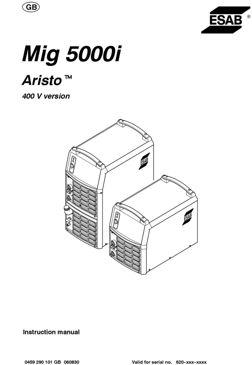
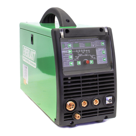
ESAB MIG400iCCCV User manual

MIG400iCCCV
INVERTER MIG/MMA
Welding Power Source
Instruction manual

1
MIG400iCCCV
INVERTER WELDING POWER SOURCE
Instruction manual
For
Installation, Operation & General maintenance

2
CONTENTS
Item
Page No.
SAFETY
3-4
RATING AND INSTALLATION
5
CAUTIONS FOR INSTALLATION
6
WELDING OPERATIONS
7-9
WIRING DIAGRAM
10
TROUBLESHOOTING
11
PARTS LIST AND EXPLODED VIEW
12-14
ESAB INDIA LOCATIONS AND CONTACT DETAILS
15

3
SAFETY
Users of ESAB welding equipment have the ultimate responsibility for ensuring that
anyone who works on or near the equipment observes all the relevant safety
precautions. Safety precautions must meet the requirements that apply to this type of
welding equipment. The following recommendations should be observed in addition to
the standard regulations that apply to the workplace.
Trained personnel well acquainted with the operation of the welding equipment must
carry out all the work. Incorrect operation of the equipment may lead to hazardous
situations, which can result in injury to the operator and damage to the equipment.
1. Anyone who uses the welding equipment must be familiar with:
• its operation
• location of emergency stops
• its function
• relevant safety precautions
• welding
2. The operator must ensure that:
• no unauthorized person is stationed within the working area of the equipment
when it is started up.
• no one is unprotected when the arc is struck
3. The workplace must:
• be suitable for the purpose
• be free from drafts
4. Personal safety equipment
• Always wear recommended personal safety equipment, such as safety glasses,
flameproof clothing, and safety gloves.
• Do not wear loose—fitting items, such as scarves, bracelets, rings, etc., which
could become trapped or cause burns.
5. General precautions
• Make sure the return cable is connected securely.
• Only a qualified electrician may carry out work on high voltage equipment.
• Appropriate fire extinguishing equipment must be clearly marked and close at
hand.
• Lubrication and maintenance must not be carried out on the equipment during
operation.
Read and understand the instruction manual before installing or operating.
ESAB can provide you with all necessary welding protection and accessories.

4
WARNING
Arc welding and cutting can be injurious to yourself and others. Take
precautions when welding.
Ask for your employer’s safety practices which should be based on manufacturers’
hazard data.
ELECTRIC SHOCK –Can kill
• Install and earth the welding unit in accordance with applicable
standards.
• Do not touch live electrical parts or electrodes with bare skin, wet
gloves or wet clothing.
• Insulate yourself from earth and the workpiece.
• Ensure your working stance is safe.
FUMES AND GASES –Can be dangerous to health
• Keep your head out of the fumes.
• Use ventilation, extraction at the arc, or both, to take fumes and gases
away from your breathing zone and the general area.
ARC RAYS –Can injure eyes and burn skin.
• Protect your eyes and body. Use the correct welding screen and filter
lens and wear protective clothing.
• Protect bystanders with suitable screens or curtains.
FIRE HAZARD
• Sparks (spatter) can cause fire. Make sure therefore that there are no
inflammable materials nearby.
NOISE –Excessive noise can damage hearing
• Protect your ears. Use earmuffs or other hearing protection.
• Warn bystanders of the risk.
MALFUNCTION –Call for expert assistance in the event of malfunction.
PROTECT YOURSELF AND OTHERS!
CAUTION!
This product is solely intended for arc welding
Do not dispose of electrical equipment together with normal waste!
In accordance with national law, electrical equipment that has
reached the end of its life must be collected separately and returned
to an environmentally compatible recycling facility. As the owner of
the equipment, you should get information on approved collection
systems from the local representative. By applying this Directive you
will improve the environment and human health

5
RATING
RATING OF MIG400iCCCV INVERTER WELDING POWER SOURCE
CHARACTERISTICS
CONSTANT VOLTAGE/
CURRENT TYPE
Input:
SUPPLY VOLTAGE, PHASE & FREQUENCY
415V± 15%, 3Phase, 50 Hz, AC
MAXIMUM INPUT CURRENT
26.6 A
Output:
OUTPUT CURRENT RANGE
DC 40-400A
VOLTAGE RANGE
16-34 V DC
TYPE OF WELDING CURRENT CONTROL
STEPLESS
CLASS OF INSULATION
‘H’
COOLING
FORCED AIR COOLED
APPROX DIMENSION (LxWxH) IN MM
654 x 322 x 671
WEIGHT (APPROX)
50.5 KG.
INSTALLATION
The complete installation for MIG application should consist the following items:
Description
Type
Quantity
1.
Welding Power Source
MIG400iCCCV
1
2.
Wire feeder with
Interconnections, Wire
spool
MIG400i wire
feeder
1
3.
MIG Torch for MIG
1
4.
Earth cable with Clamp
1
5.
Heater - optional
110V A.C. for CO2
1
6.
GAS with regulator
1
The complete installation for MMA application should consist the following items:
Description
Type
Quantity
1.
Welding Power Source
MIG400iCCCV
1
2.
Welding Cable with
Electrode Holder.
1
3.
Earth cable with Clamp
1

6
CAUTIONS FOR INSTALLATION
Provide a Switch Box for every Welding Power Source, and use designated
fuse
Tolerance of Power Voltage Variation is 10% of rated input voltage.
a) Installation place
Install in the place where less moisture and dust exist. Avoid direct sunlight and
rain, and maintain ambient temperature within –10o to +45o C as much as
possible.
Keep the welding power source at least 20 cm. away from the wall (if any).
In case of installation of more two units side by side, a distance of more than 20
cm is recommended between the two power sources.
Use a shield to protect the welding arc in case of excessive air draft.
b) Ventilation
Adequate ventilation is recommended at the place of installation. For
example the following guideline should be followed:
a) In case of the area being more than 300 square meters (per unit), no
ventilation is required, provided the room is not completely airtight.
b) In case of the area being less than 300 square meters and the welding
is continuously performed, adequate ventilation is recommended with
the help of vent fan or exhaust duct.
c) While performing the grounding work, it is recommended that a skilled
electrician does the work.

7
WELDING OPERATIONS
1. Current meter
2. Voltage meter
3. Crater Current
4. Crater Voltage
5. MMA/ MIG switch
6. Wire feeder control circuit socket
7. Power Socket +
8. Power indicating light
9. Protection indicating light
10. Current Inductance control
11. Welding mode selection switch
12. Crater OFF/ON (2T/4T) selection switch
13. Power Socket —
1. Power switch
2. Heater socket AC110V)
3. Controlling power trip (3A)
4. Fan
5. Earthing bolt
6. Cable fixed head
7. Power input cable
8. Nameplate
Indicating light
Only Green light on: The power is on.
Green light on, Red light on: The machine is overheated. The machine will go back to
working condition, if the inner temperature of machine returns to the allowed level.

8
MIG MODE
Put MMA/ MIG switch on power source in MIG mode.
Crater Control (2T/4T)
Usually there is a crater at the end of welding. Adjust Crater Voltage and Current to fill
up the crater by arc ending current (less than 40%-70% of welding current) and
improve the welding quality. It also selects 2T/4T operation of the machine.
Soft wire feeding
In order to get the satisfying welding quality, the machine feed the wire at preset low
speed before wire touch the work piece. The speed will reach the normal level after
striking arc. It means striking arc fail if the current is not detected during this stage.
This kind of striking arc mode can improve the success of striking arc and ensure the
reliable and stable arc.
Burn back time
When the trigger of torch is switched off, the wire feeding will continue because of
inertia. So the wire will go out to the top end of torch after the welding. It will cause the
stick of wire to the work piece, thus bring the difficulty to the next welding. The burn
back is set in the machine to solve this problem. The machine will keep output voltage
during certain time to keep wire burning.
Current Inductance control
It means electronic reactor. It can adjust wire burning power by changing the current
changing speed, and reduce the spatter.
Ball cutting
Usually there is a big droplet at the end of wire after welding. And slag will stick on the
low surface of the droplet. It will cause difficulty of striking arc. The ball cutting circuit is
designed to cut the droplet automatically after welding.
Post-gas
3 seconds post-gas time is set to protect the welding area after welding.

9
Control on wire Feeder
1. Welding Current Setting.
2. Wire Inch Push Button.
3. Welding Voltage Setting.
MMA MODE
Put MMA/MIG switch on power source in MMA mode.
Welding current can be set by MMA current setting knob on the power source.

10

11
TROUBLESHOOTING
No.
Breakdown
Analysis
Solutions
1
Protecting
indicating light
ON
Thermal reply is broken.
Replace thermal relay.
The machine is
overheated.
Restart work when the temperature
returns to normal level.
2
Fan doesn’t work
Fan is defective. / The
connecting lead is
disconnected.
Replace fan, /Reconnect the lead.
3
No values
displayed on
current meter or
voltage meter
Meters are broken.
Replace meters
Connecting lead is
disconnected.
Reconnect the lead
Main control PCB is
defective.
Replace PCB
4
Current knob
doesn’t work.
Lead is disconnected
Reconnect lead
Potentiometer is broken.
Replace potentiometer
5
Machine doesn’t
work after
pressing torch
trigger.
Fuse (1A) is broken.
Replace fuse
Torch trigger is defective.
Connect control cable Torch
switch
Machine Trips
Please work under suitable duty
cycle.
Control PCB is broken.
Replace Control PCB
6
No wire feeding.
Control cable is
disconnected.
Reconnect control cable
Fuse on the back of
machine is broken.
Replace fuse
Wire feeder motor is
defective.
Repair or replace motor
Control PCB is defective.
Replace control PCB
7
No OCV
Over voltage, voltage
lack, or lack of phase
Restart the work when the voltage
returns to normal level.
The machine is over
heated.
Restart work when the temperature
returns to normal level.
Power switch is defective.
Replace power switch
8
No gas
Fuse (1A) is defective.
Replace fuse
Gas hose is
disconnected.
Reconnect gas hose
Gas hose is staved or
jammed.
Check gas route
Solenoid is defective.
Repair or replace solenoid

12
Parts List and Exploded view
No.
QTY
ESAB CODE NO
ESAB ITEM DESCRIPTION
1
1
0800660001
MAIN TRANSFORMER(MIG400iCCCV)
2
1
0800660002
FILTER CAPACITOR(MIG400iCCCV)
3
1
0800660003
RES'NCE INDUCTANCE(MIG400iCCCV)
4
1
0800660004
MAIN CONTROL BRD(MIG400iCCCV)
5
1
0800660005
CONTROL TRANSF. 1(MIG400iCCCV)
6
1
0800660006
PWM CONTROL WIRE(MIG400iCCCV)
7
1
0800660007
CONTROL TRANSF. 2(MIG400iCCCV)
8
1
0800660008
TOP PANEL(MIG400iCCCV)
9
2
0800660009
TOP PANEL STRENGT RIB(MIG400iCCCV)
10
1
0800660010
COMMON MODE CHOKE(MIG400iCCCV)
11
1
0800660011
PWM AND DRIVE BRD(MIG400iCCCV)
12
1
0800660012
CUR&VOLT FEEDBACK WIRE(MIG400iCCCV)
13
1
0800660013
MOUNTING PANEL(MIG400iCCCV)
14
1
0800660014
CUR.INDUCTANCE SUPP(MIG400iCCCV)
15
1
0800660015
CUR SAMPLING BRD(MIG400iCCCV)
16
1
0800660016
RADIATOR CONN.BRD(MIG400iCCCV)
17
1
0800660017
IGBT RADIATOR(MIG400iCCCV)
18
1
0800660018
BOTTOM PANEL(MIG400iCCCV)
19
1
0800660019
BACK PANEL(MIG400iCCCV)
20
1
0800660020
CABLE FIXED HEAD(MIG400iCCCV)
21
1
0800660021
POWER CORD(MIG400iCCCV)
22
1
0800660022
ELCB (MIG400iCCCV)
23
2
0800660023
SWITCH SUPPORT(MIG400iCCCV)
24
1
0800660024
TWO PIN SOCKET(MIG400iCCCV)
25
1
0800660025
FUSE SUPPORT(MIG400iCCCV)
27
1
0800660026
AXIAL FLOW FAN(MIG400iCCCV)
28
1
0800660027
RIGHT PANEL(MIG400iCCCV)
29
2
0800660028
WIND SCREEN(MIG400iCCCV)
30
2
0800660029
ABSORB CAPACITOR(MIG400iCCCV)
31
4
0800660030
IGBT BUSBAR(MIG400iCCCV)
32
1
0800660031
IGBT ABSORB CAP. SUPP(MIG400iCCCV)
33
1
0800660032
PRIMARY ABSORB BRD(MIG400iCCCV)
34
2
0800660033
FILTER INDUCTANCE(MIG400iCCCV)
35
2
0800660034
IGBT(MIG400iCCCV)
36
1
0800660035
3P RECTIF. BRIDGE(MIG400iCCCV)
37
1
0800660036
THERMORELAY(MIG400iCCCV)
38
1
0800660037
RADIATOR SUPPORT(MIG400iCCCV)
39
2
0800660038
FILTER CAPACITOR(MIG400iCCCV)
40
4
0800660039
POLY'LENE CAPACITOR(MIG400iCCCV)
41
1
0800660040
OUTPUT RADIATOR(MIG400iCCCV)
42
2
0800660041
OUTPUT FIXED BRD(MIG400iCCCV)
43
2
0800660042
EU TYP QUICK CONN.(MIG400iCCCV)

13
44
1
0800660043
AVIATION SOCKET(MIG400iCCCV)
45
1
0800660044
SHUNT(MIG400iCCCV)
46
1
0800660045
RESISTANCE(MIG400iCCCV)
47
1
0800660046
PANEL(MIG400iCCCV)
48
1
0800660047
WAVE SWITCH(MIG400iCCCV)
49
3
0800660048
POTENTIOMETER KNOB(MIG400iCCCV)
50
2
0800660049
WAVE SWITCH(MIG400iCCCV)
51
2
0800660050
DIG.DISPLAY CUR MTR(MIG400iCCCV)
52
1
0800660051
LUMINOUS DIODE(MIG400iCCCV)
53
1
0800660052
LUMINOUS DIODE(MIG400iCCCV)
54
1
0800660053
LEFT PANEL(MIG400iCCCV)
55
1
0800660054
OUTPUT ABSORB BRD(MIG400iCCCV)
56
1
0800660055
COMMUTATION
INDUCTANCE(MIG400iCCCV)
57
2
0800660056
SEC. ABSORB BOARD(MIG400iCCCV)
58
2
0800660057
FAST RECOVERY DIODE(MIG400iCCCV)
59
1
0800660058
FAST RECOVERY RADIATOR(MIG400iCCCV)

14
Table of contents
Other ESAB Welding System manuals

ESAB
ESAB RS 400 User manual

ESAB
ESAB Caddy Mig C160i User manual

ESAB
ESAB AristoFeed 30- 4 User manual

ESAB
ESAB YardFeed 200 User manual

ESAB
ESAB Aristo Mig 5000i 460 V User manual

ESAB
ESAB MIGMATIC 250 User manual

ESAB
ESAB AristoMig 4004i Pulse User manual

ESAB
ESAB ET 186i AC/DC User manual

ESAB
ESAB OCF 2L User manual

ESAB
ESAB ST-21M User manual

ESAB
ESAB Thermal Dynamics CUTMASTER 40 User manual

ESAB
ESAB TAE 800 User manual

ESAB
ESAB A2 Multitrac Guide

ESAB
ESAB SDE-100 User manual

ESAB
ESAB LAF 1251 User manual

ESAB
ESAB Aristo U6 User manual

ESAB
ESAB Origo Arc 4001i User manual

ESAB
ESAB Mig 4004 iMV Guide
ESAB
ESAB Renegade ET 300i User manual

ESAB
ESAB migmaster 215 pro User manual