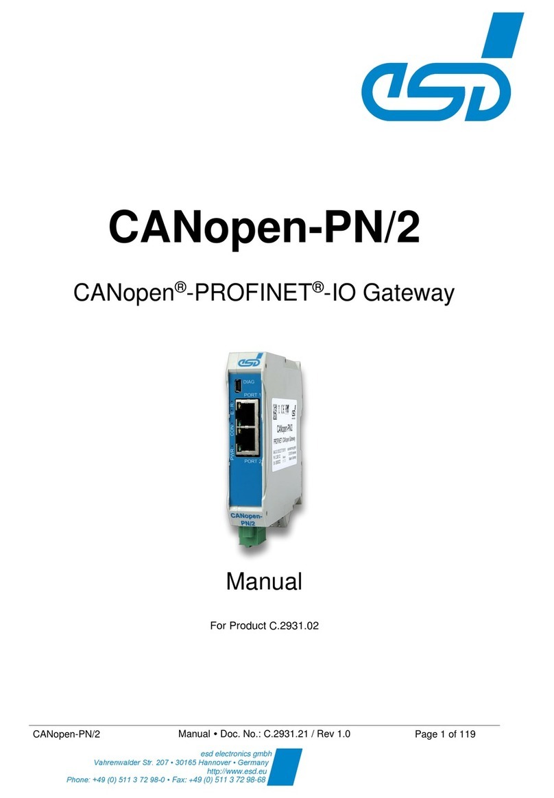
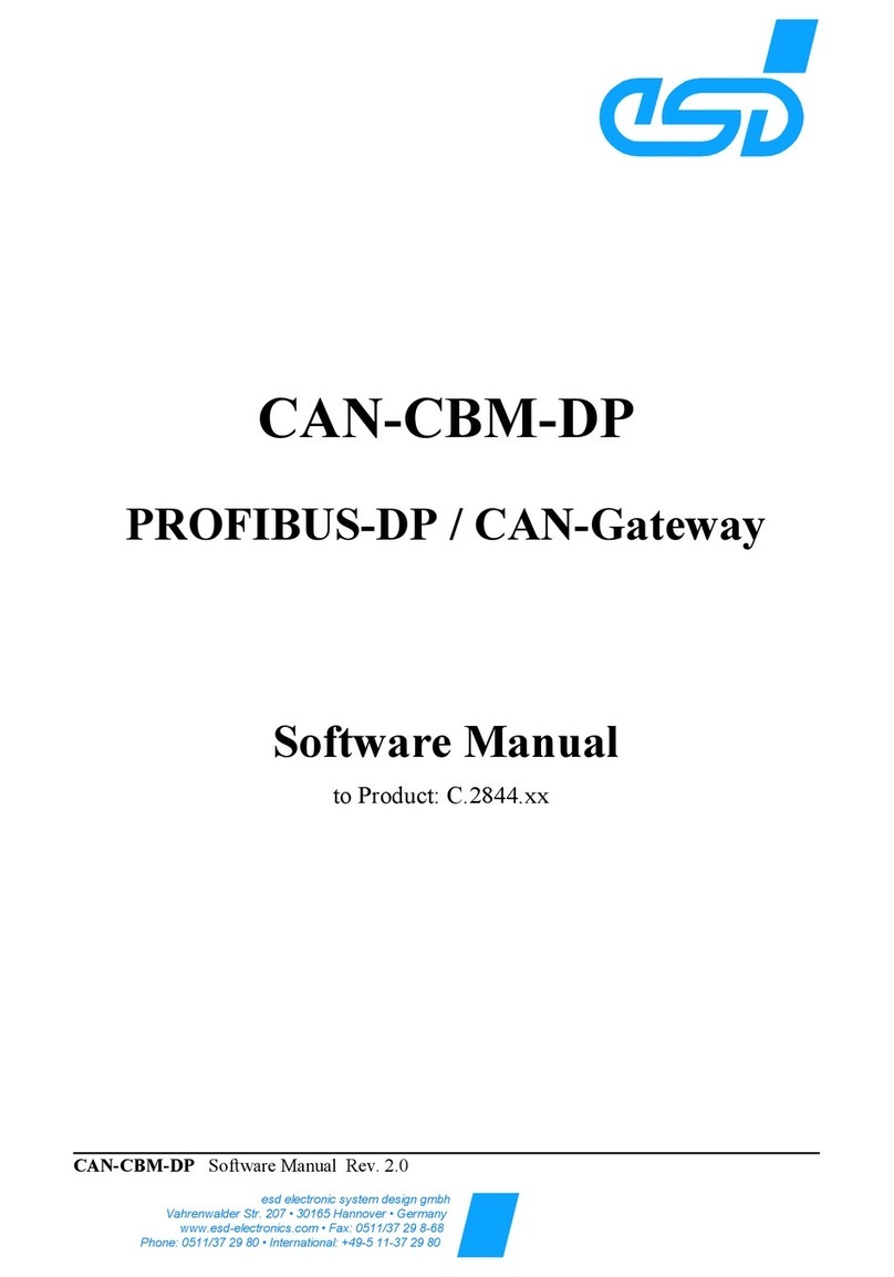
ESD CAN-PN User manual

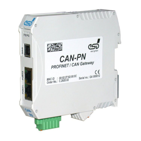
CAN-PN
PROFINET IO / CAN Gateway
Hardware Manual
to Product C.2920.02
CAN-PN Hardware Manual • Doc. No.: C.2920.21 / Rev. 1.1 Page 1 o 35
esd electronic system design gmbh
Vahrenwalder Str. 207 • 30165 Hannover • ermany
http://www.esd.eu • Fax: 0511/37 29 8-68
Phone: 0511/37 29 80 • International: +49-5 11-37 29 80

N O T E
The in ormation in this document has been care ully checked and is believed to be entirely reliable.
esd makes no warranty o any kind with regard to the material in this document, and assumes no
responsibility or any errors that may appear in this document. esd reserves the right to make
changes without notice to this, or any o its products, to improve reliability, per ormance or design.
esd assumes no responsibility or the use o any circuitry other than circuitry which is part o a
product o esd gmbh.
esd does not convey to the purchaser o the product described herein any license under the patent
rights o esd gmbh nor the rights o others.
esd electronic system design gmbh
Vahrenwalder Str. 207
30165 Hannover
Germany
Phone: +49-511-372 98-0
Fax: +49-511-372 98-68
E-Mail: in [email protected]
Internet: www.esd.eu
USA / Canada:
esd electronics Inc.
525 Bernardston Road
Suite 1
Green ield, MA 01301
USA
Phone: +1-800-732-8006
Fax: +1-800-732-8093
E-mail: [email protected]
Internet: www.esd-electronics.us
Page 2 o 35 Hardware Manual • Doc. No.: C.2920.21 / Rev. 1.1 CAN-PN

Document file: I:\Texte\Doku\MANUALS\CAN\CAN-PN\Englisch\CAN-PN_Hardware_en_11.odt
Date of print: 2009-09-30
Document type num er: DOC0800
Firmware version: rom Rev. 1.0
Document History
The changes in the document listed below a ect changes in the hardware as well as changes in
the description o the acts, only.
Revision Chapter Changes versus previous version Date
1.0 all First version o English hardware manual 2009-06-23
1.1
- Security and con ormity notes inserted at the beginning o the manual.
2009-09-30
1. Number o maximum input and output data changed.
1.1 Chapter "Sa ety Instructions" inserted.
1.2 Chapter "Service Note" inserted.
3. Chapter "Starting Up" inserted
8. Appendix inserted.
Descriptions concerning optional InRailBus moved to appendix.
Technical details are subject to change without urther notice.
CAN-PN Hardware Manual • Doc. No.: C.2920.21 / Rev. 1.1 Page 3 o 35

Safety Instructions and Conformity
!When working with CAN-PN ollow the instructions below and read the manual care ully to
protect yoursel and the CAN-PN rom damage.
The esd guarantee does not cover damages which result rom improper use or disregard o
sa ety instructions and warnings.
!Do not open the housing o the device. It does not contain any serviceable parts and does
not require any manual con iguration o the hardware.
Dismantling the housing by personnel which is not authorized by esd causes the loss o all
warranty claims.
!In order to prevent overvoltage damage due to thunder storm, unplug the device rom USB
and CAN be orehand.
!Never let liquids get inside the device. Otherwise, electric shocks or short circuits may result.
!Protect the device rom dust, moisture and steam. Remove all cables be ore cleaning. Clean
the device with a slightly moist, lint- ree cloth. Cleaning agents or solvents are not suitable.
!Protect the device rom shocks and vibrations.
!The device may become warm during normal use. Always allow adequate ventilation around
the device and use care when handling.
!Do not operate the device adjacent to heat sources and do not expose it to unnecessary
thermal radiation. Ensure an ambient temperature o 0°...50 °C.
!Do not use damaged or de ective cables to connect the device and ollow the CAN wiring
hints at the end o the manual.
!The device is intended or indoor use only.
!The operation o the device in hazardous areas, or areas exposed to potentially explosive
materials is not permitted.
!The operation o the device or medical purposes is prohibited.
!The CAN-PN is an industrial product and meets the demands o the EU regulations and
EMC standards printed in the con ormity declaration at the end o this manual.
Warning: In a residential, commercial or light industrial environment the CAN-PN may
cause radio inter erences in which case the user may be required to take
adequate measures.
Page 4 o 35 Hardware Manual • Doc. No.: C.2920.21 / Rev. 1.1 CAN-PN

Ta le of contents
1. Overview......................................................................................................................................7
1.1 Sa ety Instructions.................................................................................................................8
1.2 Service Note..........................................................................................................................8
2. Hardware-Installation....................................................................................................................9
2.1 Connections...........................................................................................................................9
2.2 LEDs....................................................................................................................................10
2.2.1 LED-Assignment.........................................................................................................10
3. Starting Up.................................................................................................................................12
4. Technical Data...........................................................................................................................13
4.1 General Technical Data.......................................................................................................13
4.2 Microcontroller.....................................................................................................................13
4.3 CAN Inter ace......................................................................................................................14
4.4 PROFINET IO Inter ace.......................................................................................................14
4.5 DIAG, Serial Inter ace via USB-Inter ace.............................................................................14
4.6 Order In ormation.................................................................................................................15
5. Inter aces and Connector Assignments......................................................................................16
5.1 24V-Power Supply Voltage..................................................................................................16
5.1.1 Connector Assignment ...............................................................................................16
5.2 CAN.....................................................................................................................................17
5.2.1 Connector Assignment................................................................................................18
5.3 24V and CAN via InRailBus ................................................................................................19
5.4 PORT1, PORT2 - PROFINET IO.........................................................................................20
5.4.1 Connector Assignment................................................................................................20
5.5 DIAG....................................................................................................................................21
5.5.1 De ault Settings o CAN-PN........................................................................................21
5.5.2 Connector Assignment................................................................................................21
6. Correctly Wiring Electrically Isolated CAN Networks..................................................................22
7. CAN-Bus Troubleshooting Guide...............................................................................................26
7.1 Termination..........................................................................................................................26
7.2 CAN_H/CAN_L-Voltage ......................................................................................................27
7.3 Ground.................................................................................................................................27
7.4 CAN Transceiver Resistance Test ......................................................................................28
8. Appendix InRailBus (Option)......................................................................................................29
8.1 Order In ormation InRailBus Accessories............................................................................29
8.2 Connector Assignment ........................................................................................................30
8.3 Using InRailBus (Option).....................................................................................................31
8.4 Installation o the Module Using InRailBus-Connector.........................................................31
8.4.1 Connecting Power Supply and CAN Signals to CBX-InRailBus...................................33
8.4.2 Connection o the Power Supply Voltage....................................................................33
8.4.3 Connection o CAN......................................................................................................34
8.5 Remove the CAN-CBX Module rom InRailBus....................................................................34
CAN-PN Hardware Manual • Doc. No.: C.2920.21 / Rev. 1.1 Page 5 o 35

This page is intentionally le t blank.
Page 6 o 35 Hardware Manual • Doc. No.: C.2920.21 / Rev. 1.1 CAN-PN

Overview
1. Overview
Figure 1: Block circuit diagram
The module CAN-PN can link any PROFINET IO-controller to a CAN network. The CAN-PN
gateway itsel operates as a PROFINET IO-device with a maximum o 256 bytes input data and
256 bytes output data on the PROFINET IO bus.
The CAN-PN connects CAN modules with CANopen (CiA DS 301) or layer-2 (ISO 11898-1)
applications to e.g. a SIMATIC-S7.
The number o CAN participants is not limited by the gateway.
The CAN-PN module operates internally with an ARM processor ERTEC200 type, which bu ers
the CAN and PROFINET IO data in a local SDRAM. The irmware and con iguration data are kept
in the Flash. Parameters are stored by means o a serial EEPROM.
The CAN high speed (ISO 11898-2) compatible CAN-inter ace allows a maximum data-trans er
rate o 1 Mbit/s.
The 100BASE-TX PROFINET-IO inter ace is compatible to IEEE802.3 and runs with 100 Mbit/s.
The PROFINET-IO as well as the CAN inter ace are electrically isolated.
According to standard, the PROFINET-IO inter ace is equipped with two RJ-45-sockets. An
Ethernet switch is integrated in the ERTEC200.
CAN is connected via a 5-pin COMBICON spring orce plug.
The module can be con igured via PROFINET IO con iguration tool, e.g. the PLC SIMATIC
Manager. No additional con iguration tools are required!
CAN-PN Hardware Manual • Doc. No.: C.2920.21 / Rev. 1.1 Page 7 o 35
ERTEC200
Physical
CAN
Layer
ISO11898-2
EEPROM
Power Supply
24 V=
+5V=
+5V=
DC/DC
Converter
5-pole
Open style
Connector
Combicon 5.08
Power Supply
4 MB
Flash
32 MB
SDRAM
CAN Controller
SJA1000
PORT 1
RJ45
100BASE-TX
PORT 2
RJ45
100BASE-TX
LEDs
USB
Logic
PROFINET IO
Electrical Isolation
In-Rail-Bus
Connector
C A N
DIAG
USB-A

Overview
1.1 Safety Instructions
When working with CAN-PN ollow the instructions and in ormation about sa ety and con ormity
(see page 4) and read the manual care ully to protect yoursel and the CAN-PN rom damage.
The intended use is the operation o the CAN-PN as PROFINET IO / CAN gateway.
The esd guarantee does not cover damages which result rom improper use or disregard o sa ety
instructions and warnings.
1.2 Service Note
The CAN-PN does not contain any parts that require maintenance by the user.
Page 8 o 35 Hardware Manual • Doc. No.: C.2920.21 / Rev. 1.1 CAN-PN

Hardware-Installation
2.2 LEDs
2.2.1 LED-Assignment
Figure 3: Position o the LEDs in the ront panel
LED Colour Function Indication Description
LED name
in
schematic
diagram
Fyellow Identi ication
o no request o the SIMATIC-Manager or
identi ication o the unit LED1A
blinking request o the SIMATIC-Manager or
identi ication o the unit
Ered PROFINET IO
link status
o valid PROFINET IO connection exists
LED1B
on no valid PROFINET IO connection
Pgreen Firmware
booted
o irmware not yet booted.
LED1C
on irmware booted.
Cgreen CAN bus
status
o no power supply
LED1D
1x short
lash CAN Error (morse code "E")
3x short
lash CAN O (morse code "O")
short-long-
long CAN Warning (morse code "W")
on CAN bus OK
Ta le 1: Indication o the LEDs
Page 10 o 35 Hardware Manual • Doc. No.: C.2920.21 / Rev. 1.1 CAN-PN

Hardware-Installation
PROFINET-IO-RJ-45-Socket-LEDs of PORT1 and PORT2
LED Colour Indication Description
Link green o no PROFINET IO or Ethernet connection
on PROFINET IO or Ethernet connection exists.
Activity yellow
o no PROFINET IO connection
blinking con iguration
on PROFINET IO connection active
Ta le 2: Indication o the RJ-45-LEDs
CAN-PN Hardware Manual • Doc. No.: C.2920.21 / Rev. 1.1 Page 11 o 35

Starting Up
3. Starting Up
To start up the CAN-PN ollow the instructions below.
Step see
chapter
see
page
Read the safety instructions at the eginning of this document
carefully efore you start with the hardware installation! - 4
1. Mount the CAN-PN module and connect power supply voltage CAN
bus and PROFINET-IO. 2.1 9
2. Please remember that the CAN bus has to be terminated at both
ends. esd o ers T-connectors and terminators. Additionally, the
CAN-GND-signal has to be grounded at exactly one point in the
CAN network. There ore the CAN termination connectors o ered by
esd have got a grounding contact.
A CAN device whose CAN inter ace is not electrically isolated
corresponds to the grounding o the CAN-GND.
- -
3. Continue with the installation o the so tware, as described in the
so tware manual o the CAN-PN in chapter: 'Implementation'.
- -
Page 12 o 35 Hardware Manual • Doc. No.: C.2920.21 / Rev. 1.1 CAN-PN

Technical Data
4. Technical Data
4.1 General Technical Data
Power supply voltage nominal voltage 24 V/DC ±10%,
current consumption (24 V, 20 °C): typical: 120 mA
Connectors 24V
CAN
DIAG
PORT1,
PORT2
InRailBus
24V-power supply voltage
(X1, 4-pin COMBICON-plug with spring-cage connection)
CAN bus inter ace
(X2, 5-pin Phoenix Contact MC 1,5/5-GF-3,81)
DIAG-inter ace (X3, USB-socket type B)
PROFINET IO-inter ace PORT1, PORT2 (X4,
2x RJ-45-socket with integrated trans ormer and LEDs)
CAN bus inter ace and power supply voltage via InRailBus
(X5, 5-pin ME-MAX-TBUS-connector, accessories)
Temperature range 0...50 °C ambient temperature
Humidity max. 90%, non-condensing
Dimensions width: 23 mm, height: 100 mm, depth: 113 mm
(without connectors)
Weight 130 g
Ta le 3: General data o the module
4.2 Microcontroller
Microcontroller ERTEC200, 150 MHz
Memory
SDRAM: 32 MB
NOR-Flash: 4 Mbyte
SPI-EEPROM 128Kbit
Ta le 4: Microcontroller unit
CAN-PN Hardware Manual • Doc. No.: C.2920.21 / Rev. 1.1 Page 13 o 35

Technical Data
4.3 CAN Interface
Number o CAN inter aces 1 x CAN
CAN controller SJA1000, ISO 11898-1
Electrical isolation
500 V (e ective)
between CAN potential and module-system-potential
with pollution degree 1
Physical CAN Layer Physical Layer according to ISO 11898-2, transmission rate
programmable rom 10 Kbit/s to 1 Mbit/s
Bus termination Terminating resistor has to be set externally, i required
Connector CAN (X2) 5-pin COMBICON or optional via InRailBus (X5)
Ta le 5: Data o the CAN inter ace
4.4 PROFINET IO Interface
Number o inter aces 2, PROFINET IO PORT1, PORT2
Connection
RJ-45, BASE-TX, 100 Mbit/s, compatible to IEEE 802.3,
electrical isolation via RJ-45-socket with integrated
trans ormer
Controller ERTEC200
Connector PORT1, PORT2 (X4),
2x RJ-45 socket with integrated trans ormer and LEDs
Ta le 6: Data o PROFINET IO inter ace
4.5 DIAG, Serial Interface via USB-Interface
Type USB, Virtual COM Port
USB-speci ication USB 2.0 Full Speed (12Mbit/s)
Connector DIAG (X3), USB-socket type-B
Ta le 7: Data o the USB inter ace
Page 14 o 35 Hardware Manual • Doc. No.: C.2920.21 / Rev. 1.1 CAN-PN

Technical Data
4.6 Order Information
Type Properties Order No.
CAN-PN PROFINET IO- CAN Gateway,
CAN 2.0A/B (11/29-Bit CAN-ID), GSD ile C.2920.02
Manuals:
CAN-PN-MD CAN-PN Manual in German
(Hardware and so tware manual) C.2920.20
CAN-PN-ME CAN-PN Manual in English
(Hardware and so tware manual) C.2920.21
Ta le 8: Order in ormation
CAN-PN Hardware Manual • Doc. No.: C.2920.21 / Rev. 1.1 Page 15 o 35

Interfaces and Connector Assignments
5. Interfaces and Connector Assignments
5.1 24V-Power Supply Voltage
The power supply voltage can be ed via connector 24V (X1) or optional via InRailBus (connector
assignment see page 19).
5.1.1 Connector Assignment
Device connector: Phoenix Contact MSTBO 2,5/4-G1L-KMGY
Line connector: Phoenix Contact FKCT 2,5/4-ST, 5.0 mm pitch,
spring-cage connection,
Phoenix Contact order No.: 19 21 90 0 (included in the scope o delivery)
Pin Position:
Pin Assignment:
Pin 1 2 3 4
La elling of
CAN-PN • • M P
Signal Do not
connect!
Do not
connect!
M24
(GND)
P24
(+ 24 V)
Please, re er also to the connecting diagram on page 9.
Attention!
It is not permissi le to eed through the power supply voltage through the connector
X1 and to supply the power supply voltage to another CAN module station!
A eed through o the +24 V power supply voltage can cause damage on the modules.
Signal Description:
P24... power supply voltage +24 V ± 10 %
M24... re erence potential
Page 16 o 35 Hardware Manual • Doc. No.: C.2920.21 / Rev. 1.1 CAN-PN

Interfaces and Connector Assignments
5.2 CAN
An 82C251 is used as driver unit. The di erential CAN Bus signals are electrically isolated rom the
other signals via dual digital isolator and DC/DC-converter.
Figure. 4: CAN-Inter ace
The CAN inter ace can be connected via CAN connector (X2) or optional via InRailBus.
Use the mounting-rail bus connector o the CBX-InRailBus or the connection via the InRailBus,
see order in ormation in the appendix (page 29).
CAN-PN Hardware Manual • Doc. No.: C.2920.21 / Rev. 1.1 Page 17 o 35
VIB
VOA
GND1
VOB
VIA
VDD2
GND2
VDD
TX
R/GND
BUSL
RX BUSH
5V
+
+
- -
+5V
CAN_GND
DC/DC
S7U-0505
GND
5V
5.0V
GND
VC120605D150
CAN Tran ceiver
PCA82C251
100nF
VDD1
CAN_Tx
CAN_Rx
CAN_L
CAN_H
2
4
CAN_GND 1
4
+24 V
5
GND
CAN_L
CAN_H
3
1
CAN_GND
2
3
5.0V
Digital I olator
ADuM1201BRZ
100nF
FE
Shield
X2
MC 1,5/5-GF-3,81
X5
InRailBu
S
(Connection
to top hat rail)
Functional
earth contact
(FE)

Interfaces and Connector Assignments
5.2.1 Connector Assignment
Device connector: Phoenix Contact MC 1,5/5-GF-3,81
Line connector: Phoenix Contact FK-MCP 1,5/5-STF-3,81, spring-cage connection
Phoenix Contact order No.: 1851261 (included in delivery)
Pin Position: Pin Assignment:
(Illustration o device
connector)
1
2
3
4
5
Pin Signal
1 CAN_GND
2 CAN_L
3 Shield
4 CAN_H
5 -
Signal Description:
CAN_L, CAN_H ... CAN signals
CAN_GND ... re erence potential o the local CAN physical layer
Shield ... pin or line shield connection (using hat rail mounting direct contact to the
mounting rail potential)
- ... not connected
Recommendation of an adapter ca le from 5-pin COMBICON (here line connector
FK-MCP1,5/5-STF_3,81 with spring-cage-connection) to 9-pin DSUB:
The assignment o the 9-
pin DSUB-connector is
designed according to
CiA DS-102.
The assignment o the
5-pin Mini- COMBICON
is designed according to
CiA DR-303 Part 1
Page 18 o 35 Hardware Manual • Doc. No.: C.2920.21 / Rev. 1.1 CAN-PN

Interfaces and Connector Assignments
5.3 24V and CAN via InRailBus
Power supply voltage and CAN can optionally be ed via InRailBus.
Use the mounting-rail bus connector o the CBX-InRailBus or the connection via the InRailBus,
see order in ormation in the appendix (page 29).
Take notice o the instructions or connecting power supply and CAN signals via InRailBus in the
appendix!
CAN-PN Hardware Manual • Doc. No.: C.2920.21 / Rev. 1.1 Page 19 o 35

Interfaces and Connector Assignments
5.4 PORT1, PORT2 - PROFINET IO
An Ethernet-Switch and the Ethernet PHYs are integrated in the ERTEC200.
The PROFINET IO ports PORT1 and PORT2 have got equal rights and no pre erred direction.
Figure. 5: Example or the connection o PROFINET IO-ports
5.4.1 Connector Assignment
Device connector: 2x RJ45 with integrated trans ormer and LEDs (yellow/green)
Connector View:
Pin Assignment:
The pin assignment is designed compatible to IEEE 802.3 or 100BASE-TX, RJ45 socket.
Page 20 o 35 Hardware Manual • Doc. No.: C.2920.21 / Rev. 1.1 CAN-PN
Ethernet
Switch
CAN-PN
PROFINET IO-Device
PLC
IO-Controller
PROFINET
PORT2
PROFINET
PORT1
to other
PROFINET IO-Devices
Other manuals for CAN-PN
1
This manual suits for next models
1
Table of contents
Other ESD Gateway manuals
Popular Gateway manuals by other brands

KIWIGRID
KIWIGRID Energy Manager VoyagerX quick start guide

Thor Broadcast
Thor Broadcast H-8ATSC-IP user manual

Brocade Communications Systems
Brocade Communications Systems Gateway Administrator's guide

RTA
RTA 460ECMC-NNA1 Product user guide

WELLTECH
WELLTECH ATA-151 quick guide

hilscher
hilscher NIOT-E-TIB100-GB-RE user manual