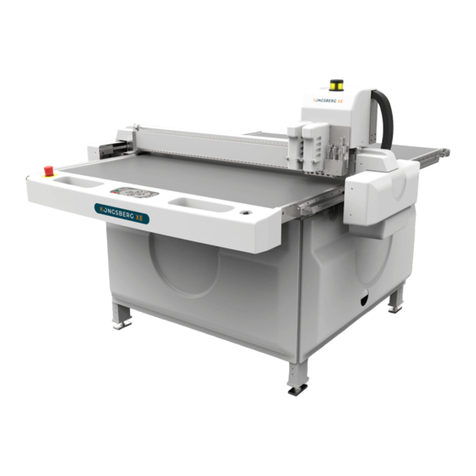
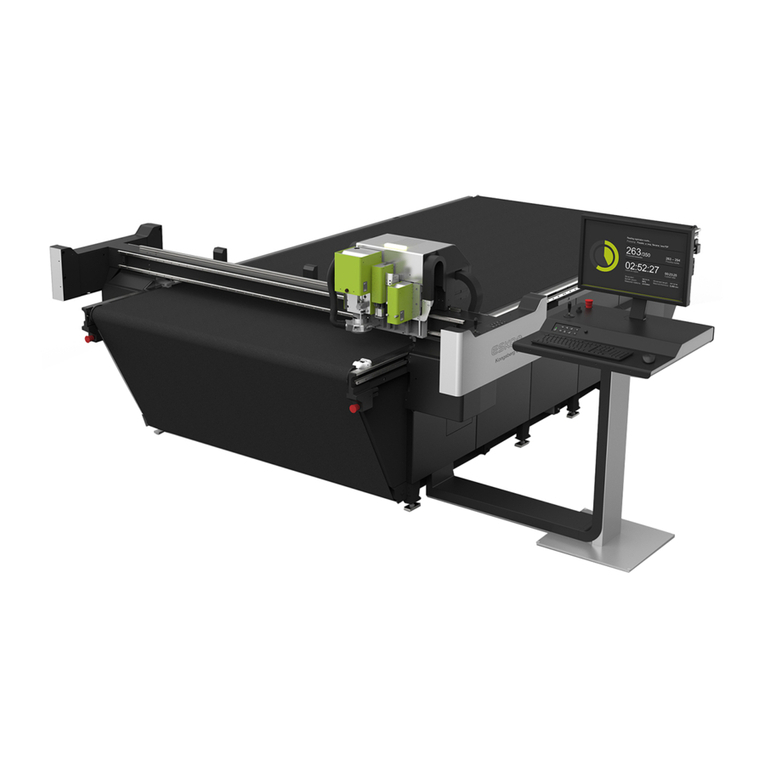
Esko Kongsberg XN IPC 2.0 User manual

Kongsberg XN / iPC 2.0
User Manual
01 - 2017 | XN

Kongsberg XN / iPC 2.0
ii
Contents
1. Preface......................................................................................................................................................... 7
2. Change Record........................................................................................................................................... 8
3. Welcome...................................................................................................................................................... 9
4. Using this manual................................................................................................................................... 10
4.1 Main Sections................................................................................................................................... 10
4.2 Name Styles and Symbols...............................................................................................................11
4.3 Pictures and Illustrations.................................................................................................................11
4.4 Local Languages............................................................................................................................... 12
5. Safety Regulations.................................................................................................................................. 13
5.1 Introduction...................................................................................................................................... 13
5.2 Responsibilities................................................................................................................................. 13
5.2.1 The Manufacturer.................................................................................................................. 13
5.2.2 The Customer.........................................................................................................................13
5.2.3 The Operators........................................................................................................................ 13
5.3 Requirements to be met by operators.......................................................................................... 14
5.4 Definition of use...............................................................................................................................14
5.5 Danger Zones................................................................................................................................... 14
5.5.1 Danger Zones.........................................................................................................................15
5.5.2 Moving Parts, Laser Radiation and High Voltage................................................................ 15
5.5.3 Loose Clothing........................................................................................................................16
5.5.4 Noise Level............................................................................................................................. 16
5.5.5 Ejection of Parts.....................................................................................................................16
5.5.6 i-Camera strobing light..........................................................................................................17
5.6 Warning Sign Explanation............................................................................................................... 17
5.7 Safety devices................................................................................................................................... 19
5.7.1 Overview................................................................................................................................. 19
5.7.2 Emergency Stop Button........................................................................................................ 19
5.7.3 Warning Lamp on top of Y Carriage.................................................................................... 20
5.7.4 DynaGuard Safety System.................................................................................................... 20
5.8 Protective equipment...................................................................................................................... 21
5.9 Procedures in case of malfunctions...............................................................................................21
5.10 Residual Risk, XN............................................................................................................................21
6. System Description................................................................................................................................. 24
6.1 Naming conventions........................................................................................................................ 24
6.2 Main Power Switch...........................................................................................................................25
6.3 Operators Panel............................................................................................................................... 26

Contents
iii
6.4 Variable Blow Back...........................................................................................................................27
6.5 Pressurized Air system.................................................................................................................... 28
6.6 Application programs available.......................................................................................................29
7. Basic Operations......................................................................................................................................30
7.1 Power On Sequence........................................................................................................................ 30
7.2 Reset Safety System.........................................................................................................................31
7.3 Power Off Sequence........................................................................................................................ 31
7.4 Continue after Safety Break............................................................................................................31
8. Prepare for a Job..................................................................................................................................... 33
8.1 Introduction...................................................................................................................................... 33
8.2 Create Job......................................................................................................................................... 33
8.3 Layer Setup.......................................................................................................................................33
8.4 Production Setup..............................................................................................................................34
8.5 Speed Setting....................................................................................................................................34
8.6 Flute/Grain Direction........................................................................................................................34
8.7 Vacuum Zone Selection................................................................................................................... 34
8.8 Job Execution.................................................................................................................................... 35
8.9 Milling Production............................................................................................................................ 35
8.10 Make a Pen Plot............................................................................................................................. 36
8.11 Work with X-Pad.............................................................................................................................36
9. How To Procedures, Advanced............................................................................................................. 40
9.1 Cutting Thick Materials.................................................................................................................... 40
9.2 Hard Board Production....................................................................................................................40
9.3 Multi Pass Milling............................................................................................................................. 41
9.4 Jobs including Reverse Operation...................................................................................................41
9.5 Work with different Reference Point Settings............................................................................... 42
9.6 MultiZone Production...................................................................................................................... 42
9.6.1 MultiZone, Workflow..............................................................................................................44
10. System Setup..........................................................................................................................................46
10.1 Introduction.................................................................................................................................... 46
10.2 Adjust X1 to X2 Angle.................................................................................................................... 47
10.3 Register Table Size......................................................................................................................... 47
10.4 Set Ruler Position...........................................................................................................................48
10.5 Set Main Reference Point..............................................................................................................48
10.6 Map Table Top Surface.................................................................................................................. 49
10.7 Reference Points and Coordinate System................................................................................... 49
10.8 Table Speed.................................................................................................................................... 51
10.9 Table Acceleration.......................................................................................................................... 52
10.10 Jog Settings................................................................................................................................... 52
10.11 Set Table Top Reference..............................................................................................................53
10.12 Vacuum Setup.............................................................................................................................. 53

Kongsberg XN / iPC 2.0
iv
10.12.1 Vacuum Section Configuration......................................................................................... 53
10.12.2 Using two vacuum pumps................................................................................................ 55
10.13 Router Setup.................................................................................................................................55
10.14 Conveyor Belt Control................................................................................................................. 55
10.14.1 Split Sheet Feed................................................................................................................. 56
10.14.2 Sheet Feed Correction.......................................................................................................56
10.15 Board Size.....................................................................................................................................56
11. Tool Configuration and Adjustment.................................................................................................. 57
11.1 Introduction.................................................................................................................................... 57
11.2 Adjust Active Tool...........................................................................................................................57
11.3 Tool Height Calibration.................................................................................................................. 58
11.4 Lag Settings (for Rotating Tools)...................................................................................................58
11.5 Rotation Adjustment (for Rotating tools).....................................................................................60
11.6 Center Offset Adjustment............................................................................................................. 61
11.7 Manual adjustment of Center Offset and angle......................................................................... 62
11.8 Tool Offset...................................................................................................................................... 62
11.9 Maintain Tool List (More...)............................................................................................................63
12. Tooling System....................................................................................................................................... 65
12.1 Tool handling and care..................................................................................................................65
12.2 Tool Inserts with built-in motor....................................................................................................65
12.3 Tool Heads available, overview.....................................................................................................66
12.4 Tool Head mount / dismount........................................................................................................67
12.5 FlexiHead.........................................................................................................................................67
12.6 PowerHead......................................................................................................................................69
12.6.1 ø150 mm Crease Wheel......................................................................................................70
12.6.2 Crease Adapter ø26 mm.....................................................................................................70
12.6.3 Perforation Wheel ø60 mm................................................................................................ 71
12.6.4 HD Knife Tool....................................................................................................................... 73
12.6.5 V-notch Knife........................................................................................................................73
12.7 FoamHead.......................................................................................................................................78
12.8 MultiCUT-HP....................................................................................................................................80
12.8.1 Introduction..........................................................................................................................81
12.8.2 Tool Head description......................................................................................................... 82
12.8.3 Safety Issues.........................................................................................................................86
12.8.4 Precautions...........................................................................................................................88
12.8.5 Routing Advice..................................................................................................................... 91
12.8.6 Cleaner Device..................................................................................................................... 94
12.8.7 Bits and Bit Change.............................................................................................................94
12.8.8 Chuck Change and Cleaning...............................................................................................96
12.8.9 Bit Slipping, Chuck Change............................................................................................... 100
12.8.10 Bit Length and Position...................................................................................................100
12.8.11 False Air valve.................................................................................................................. 101

Contents
v
12.8.12 Tool Adjustment...............................................................................................................101
12.8.13 Table Top and Height Adjustment..................................................................................102
12.8.14 Miscellaneous...................................................................................................................103
12.8.15 LubriCool.......................................................................................................................... 104
12.9 Chiller 1 for MultiCUT-HP............................................................................................................ 106
12.9.1 Introduction........................................................................................................................106
12.9.2 Chiller, Error Conditions....................................................................................................107
12.9.3 Chiller Heater, Operation..................................................................................................108
12.10 Chiller2016 for MultiCUT-HP..................................................................................................... 109
12.10.1 Introduction......................................................................................................................109
12.10.2 Startup.............................................................................................................................. 110
12.10.3 Error Conditions...............................................................................................................110
12.11 Measuring Foot.......................................................................................................................... 111
12.12 Laser Pointer.............................................................................................................................. 112
12.13 X-Pad........................................................................................................................................... 113
12.13.1 X-Pad Calibration............................................................................................................. 113
12.13.2 Tool Depth and X-Pad..................................................................................................... 114
12.13.3 Limitations........................................................................................................................ 114
13. Tool inserts........................................................................................................................................... 115
13.1 Ball Point Pen............................................................................................................................... 115
13.2 Bevel Knife.................................................................................................................................... 116
13.3 Bevel Knife U20............................................................................................................................117
13.4 Braille Tool.................................................................................................................................... 117
13.5 CorruSpeed Knife......................................................................................................................... 122
13.5.1 Tool adjustment................................................................................................................. 123
13.6 Crease Tool................................................................................................................................... 124
13.6.1 Tool adjustment................................................................................................................. 124
13.7 Crease Tool, 60 mm.....................................................................................................................125
13.7.1 Tool adjustment................................................................................................................. 125
13.8 Drill tools.......................................................................................................................................126
13.8.1 Flexi Drill Tool.....................................................................................................................126
13.8.2 Reboard Drill Tool..............................................................................................................127
13.8.3 Drill Bit dimensions........................................................................................................... 127
13.8.4 Tool Adjustment.................................................................................................................128
13.8.5 Drill Tool in ArtiosCAD.......................................................................................................128
13.9 Foam Knife....................................................................................................................................128
13.10 Ink Tool....................................................................................................................................... 129
13.10.1 Liquid Ink Tool................................................................................................................. 129
13.10.2 Fibertip Tool..................................................................................................................... 130
13.10.3 Tool adjustment............................................................................................................... 130
13.11 KissCut.........................................................................................................................................131
13.12 MicroCut......................................................................................................................................133
13.13 Psaligraphy Knife........................................................................................................................135

Kongsberg XN / iPC 2.0
vi
13.13.1 Tool adjustment............................................................................................................... 135
13.14 RBI 90-16 (Rigid Board Insert)...................................................................................................136
13.15 Reciprocating Knife.................................................................................................................... 137
13.15.1 Tool adjustment............................................................................................................... 138
13.16 Rigid Material Knife....................................................................................................................139
13.17 RotaCut........................................................................................................................................140
13.18 Static Knife..................................................................................................................................143
13.18.1 Tool adjustment............................................................................................................... 144
13.19 VI45 Knife Tool........................................................................................................................... 144
14. Maintenance.........................................................................................................................................147
14.1 Daily maintenance....................................................................................................................... 147
14.2 Weekly maintenance....................................................................................................................147
14.3 Maintenance, external equipment............................................................................................. 147
15. Fuse replacement................................................................................................................................148
15.1 MPU fuses.....................................................................................................................................148
15.2 X1 fuses.........................................................................................................................................149
15.3 X2 fuses.........................................................................................................................................149
15.4 Y/Z fuses....................................................................................................................................... 150
15.5 Tool Rotation/Reciprocating knife fuses.....................................................................................151
15.6 Chiller fuse....................................................................................................................................151
15.7 Heater for Chiller Fuse................................................................................................................ 153
15.8 Chiller2016 Fuse replacement.................................................................................................... 153
16. Roll Feeder............................................................................................................................................154
17. Collector Basket.................................................................................................................................. 155
18. Vacuum Cleaner.................................................................................................................................. 156
18.1 Vacuum Cleaner, Zefiro............................................................................................................... 156
18.1.1 How to use......................................................................................................................... 156
18.2 Vacuum Cleaner, High-capacity, TB ESKO..................................................................................158
18.2.1 How to use......................................................................................................................... 158
18.3 Compact Vacuum Cleaner...........................................................................................................160
18.3.1 How to use......................................................................................................................... 160
19. Install Software................................................................................................................................... 162
20. Frequently Asked Questions.............................................................................................................163
20.1 Machine.........................................................................................................................................163
20.2 Tools.............................................................................................................................................. 163
20.3 iPC..................................................................................................................................................164

1
Kongsberg XN / iPC 2.0
7
1. Preface
User Manual
for
Kongsberg XN
running i-cut Production Console 2.0
Note: We remind you that only the Esko staff, or persons having received appropriate training,
are allowed to handle, manipulate or do repairs on the system.
©Copyright 2017, Esko-Graphics Kongsberg AS, Norway
All Rights Reserved.
This copyright does not indicate that this work has been published.
This material, information and instructions for use contained herein are the property of Esko-Graphics
Kongsberg AS. There are no warranties granted or extended by this document. Furthermore, Esko-Graphics
Kongsberg AS does not warrant, guarantee or make any representations regarding the use, or the results
of the use of the system or the information contained herein. Esko-Graphics Kongsberg AS shall not be
liable for any direct, indirect, consequential or incidental damages arising out of the use or inability to use
the system or the information contained herein. The information contained herein is subject to change
without notice. Revisions may be issued from time to time to advise of such changes and/or additions.
No part of this system may be reproduced, stored in a data base or retrieval system, or
published, in any form or in any way, electronically, mechanically, by print, photoprint, microfilm
or any other means without prior written permission from Esko-Graphics Kongsberg AS.
This document supersedes all previous dated versions.
Correspondence regarding this publication should be forwarded to:
Global support
Esko-Graphics Kongsberg AS
Document no: D3625
Part no: 32599375
Esko-Graphics Kongsberg AS
www.esko.com
P.O.Box 1016, N-3601 Kongsberg, Norway
Tel: +47 32 28 99 00 Fax: +47 32 28 85 15 / 32 28 67 63

2Kongsberg XN / iPC 2.0
8
2. Change Record
Date
dd-mm-yy
By Description
20-05-2016 jhbe Document is updated according to iPC ver 2.0
06-09-2016 jhbe The importance of MultiCUT chuck cleaning is
emphasized
18-10-2016 jhbe CorruSpeed information updated
24-10-2016 jhbe MultiCUT-HP, new chiller and information
about old chiller added
15-11-2016 jhbe MultiZone Production, recommended
workflow emphasized.
18-11-2016 jhbe V-notch description improved.
28-11-2016 jhbe Measuring foot, soft springs introduced.
29-11-2016 jhbe Psaligraphy knife tool information added
14-12-2016 jhbe MultiCUT-HP chapters updated

3
Kongsberg XN / iPC 2.0
9
3. Welcome
Welcome to the User Manual for Kongsberg XN running iPC 2.0.
This manual will provide a complete and detailed description of Cutting Table functions.
There is a separate user manual for i-cut Production Console (iPC).
Thus, actual GUI functions will be referenced in this manual, but the complete and
comprehensive description is available in the User Manual for i-cut Production Console.
This manual is aimed for operators of Kongsberg Cutting Tables and people preparing files
for such equipment.
Another source for information is the manual: Get the best out of iPC 2.0.
Note: Some of the functions and equipments described in this manual are optional.

4Kongsberg XN / iPC 2.0
10
4. Using this manual
4.1 Main Sections
The manual is divided into the following Main Sections:
Safety Regulations
• All safety related issues are discussed.
System Description
• This chapter provides basic knowledge about the machine.
Basic Operations
• This chapter provides basic knowledge about how to operate the machine.
Prepare for a Job
• A typical workflow is described, with detailed information about each step.
How to Procedures, Advanced
Optional functions for the advanced user:
•Cutting Thick Materials - advices.
•Hard Board Production - advices
•Multi Pass Milling - how to.
•MultiZone Production - how to.
Tool Configuration and Adjustment
• General information about the tooling and adjustment of tools.
Tooling System
• Tool descriptions.
Maintenance
• This chapter describes maintenance to be carried out by the customer.
Fuse Replacement
• Fuse location and specification.

4
Kongsberg XN / iPC 2.0
11
Appendices
•Roll Feeder - basic information.
•Vacuum Cleaner - basic information.
•FAQ - Frequently Asked Questions
4.2 Name Styles and Symbols
Name or style Description
Pop-up dialog This is the dialog that appears when you click the Right
mouse button.
Start button The italic style indicates this is a button on the Operator
panel.
OK The bold style indicates this is a button or function in
the GUI.
Maintenance Link to topic.
Menu Bar->Edit-> Options
Menu selection: From Menu Bar, select Edit and then
Options.
This symbol indicates that the function depends upon
actual hardware.
If hardware is not available, this functions is hidden.
This symbol indicates that the function is license
dependant.
4.3 Pictures and Illustrations
Orientation
Pictures and illustrations related to the Cutting Table are viewed as illustated here:

4Kongsberg XN / iPC 2.0
12
4.4 Local Languages
This manual is available in a wide range of local languages.
Screen pictures and illustrations remains in English language.

5
Kongsberg XN / iPC 2.0
13
5. Safety Regulations
5.1 Introduction
The table is designed to conform to Safety Regulation standards.
Nevertheless, operating the table can involve hazards if:
• The operator does not follow the Operating Instructions.
• The table is used for Non-intended purposes.
In addition to the Safety Regulation described below, you will find safety warnings in the
respective topics.
5.2 Responsibilities
5.2.1 The Manufacturer
The Manufacturer is responsible for delivering the system according to Safety Regulation
standards.
5.2.2 The Customer
The Customer is responsible for:
• Ensuring that the system is used for it's Intended Use only
• Allowing that only authorized and trained personnel operate the system
• Preventive maintenance as described in the Maintenance chapter.
• That the Local Regulations regarding installation and operation are fulfilled.
5.2.3 The Operators
The Operators are responsible for:
• Operating the system only when it is in a flawless state.

5Kongsberg XN / iPC 2.0
14
• Operating the system according to Operating Instructions.
• Ensuring that no Unauthorized Personnel come close to the system.
5.3 Requirements to be met by operators
Personnel operating the system must:
• Be adequately trained.
• Have read and understood the instructions described in Safety Regulation as well as any
other safety warnings.
5.4 Definition of use
Intended use is described in the User Manual for i-cut Production Console.
In this manual, Intended use is described in the following chapters:
•Basic Operations
•Prepare for a Job
•How to Procedures, Advanced
Any other use is considered Non-intended use.
Examples of Non-intended use:
• Operation by operators not meeting the requirements as described above.
• Unauthorized modifications (bridging safety devices, removing covers etc.)
• Utilizing accessories other than those specified by Esko.
Non-intended use may cause:
• Health hazards and injuries.
• Damage to the system.
• Incorrect functionality.
• Damage to work materials.
Note: Esko is not liable for any damage resulting from such Non-intended use.
5.5 Danger Zones

5
Kongsberg XN / iPC 2.0
15
5.5.1 Danger Zones
The area around the moving parts is considered to be a Danger Zone.
The Danger Zone is identified by the means of a yellow / black floor marking.
5.5.2 Moving Parts, Laser Radiation and High Voltage

5Kongsberg XN / iPC 2.0
16
5.5.3 Loose Clothing
While working with this machine, do not:
• Use ties
• Use loose necklaces
• Use scarfs
5.5.4 Noise Level
•Hearing Protection should be used by any personnel exposed to the noise
from the machine.
5.5.5 Ejection of Parts
Potential risk when running MultiCUT:
Personnel hit by breaking milling bit or small pieces of processed material.

5
Kongsberg XN / iPC 2.0
17
•Eye Protection should be used by any
personnel working with MultiCUT.
5.5.6 i-Camera strobing light
If your system includes i-Camera, please read this warning carefully:
WARNING
i-Camera is equipped with LED strobing light.
The LED default frequency (10 Hz) is in a range that
can cause photosensitive epileptic reactions amongst
susceptible people.
If a person is known to be susceptible, the frame rate,
frequency of strobing, can be reduced to as low as 1 Hz
from the camera configuration menu.
At that rate, seizures are not known to happen.
5.6 Warning Sign Explanation
Knife Blades are extremely sharp.
This symbol is used in this documentation to indicate operations with
Knife Blades and Milling Bits.
Hand Squeeze
Potential areas with a risk of being squeezed are marked with the Hand
Squeeze sign.
These areas are:
• Between X-axis end stopper and traverse wagon.

5Kongsberg XN / iPC 2.0
18
Do not Touch
Potential areas with a risk of being squeezed are marked with the Do
Not Touch sign.
These areas are:
• Between Y carriage and rack
• Between the table top and the moving traverse.
• Underneath the tool head.
Hearing Protection
The Hearing Protection symbol indicates areas where the use of
hearing protection is compulsory.
Eye Protection
The Eye Protection symbol indicates areas where the use of eye
protection is compulsory.
Moving Parts
Potential areas with a risk of being hit by Moving Parts are
marked with the Moving Parts sign.
These areas are:
• Both traverse ends.
• Y carriage.
• Tool head(s).
The Main Power Unit (MPU) contains Mains Voltage and
may be opened by Authorized Personnel only.
The MPU is marked with the High Voltage warning sign.
Laser Radiation.
The tool head is equipped with a class II Laser Pointer.
Avoid laser light into your eyes.

5
Kongsberg XN / iPC 2.0
19
5.7 Safety devices
5.7.1 Overview
Device no Description
1Main Power Switch
2Emergency Stop Button
3Warning Lamp / Status Lamp
4Photo cell supervision, Dynaguard
5Traverse Stop Switches, Dynaguard
5.7.2 Emergency Stop Button
Switch positions:
OUT - Emergency Stop is switched OFF.
IN - Emergency Stop is switched ON; Mains Power to the machine is switched off.

5Kongsberg XN / iPC 2.0
20
Note:
Activating the Emergency Stop Button does not provide a guarantee against injury!
Due to the high kinetic energy of moving parts, do not underestimate Stop Distance of
traverse, Y carriage and Tool Head.
5.7.3 Warning Lamp on top of Y Carriage
Light is Description
Off Servo Power is off
On Servo Power is on, Safety System is enabled, table is in operation
Flashing Safety System is activated.
Reset Safety System to continue operation
5.7.4 DynaGuard Safety System
The DynaGuard Safety System consists of two light beams in front of the traverse and one
behind.
In addition, there is a stop mechanism mounted on each end of the traverse.
Machine movement will stop and Servo Power will be switched off if:
• One of the light beams are broken.
• The stop mechanism is activated, for instance when a person is standing too near the table.
Continue after DynaGuard is triggered
To continue operation, proceed as follows:
1. Ensure the table is free from obstructions and ready for operation.
2. Reset the Safety System by pressing the Pause pushbutton.
Table of contents
Other Esko Cutter manuals
Popular Cutter manuals by other brands

EINHELL
EINHELL 43.507.30 operating instructions

Delta
Delta 34-941 Operating and maintenance instructions

Lumberjack
Lumberjack TC180 Safety and operating manual

Far Tools
Far Tools TC 180B Original manual translation

CO/Tech
CO/Tech LS400-UK Original instructions

TSI Instruments
TSI Instruments TC-50 operating manual