Esko Kongsberg XE User manual

Technical Manual
Kongsberg XE and i-XE Systems
with GC900sm Controller
This manual contains a technical description of the
GC900sm Controller based Kongsberg Cutting System.
The purpose of this manual is to offer documentation necessary for service personnel.
Note
We remind you that only the Esko-Graphics staff, or persons
having received an appropriate training, are allowed to handle,
manipulate or do running repairs on the machines.
______________________________________
A Publication of: Esko-Graphics Kongsberg AS
Copyright © 1984-2009 Esko-Graphics Kongsberg AS.
This copyright does not indicate that this work has been published.
All rights strictly reserved. Reproduction or issue to third parties in any form
whatever is not permitted without written authority from the publisher.
Esko-Graphics reserves the right to change specifications without notice.
Document number: D3018
Status: 091012
Esko-Graphics Kongsberg AS
www.esko.com
P.O.Box 1016, N-3601 Kongsberg, Norway
Tel: +47 32 28 99 00 Fax: +47 32 28 85 15 / 32 28 67 63

Technical Manual Kongsberg XE/i-XE
2
1.TABLE OF CONTENT
1. TABLE OF CONTENT....................................................................................................................... 2
2. SYSTEM DESCRIPTION................................................................................................................ 5
2.1 KONGSBERG XE/I-XE TABLES,AN OVERVIEW............................................................................. 5
2.2 THE FRONT END PC ........................................................................................................................ 6
2.2.1 Hypertreading....................................................................................................................... 6
2.2.2 Power save............................................................................................................................ 6
2.3 XE AND I-XE TABLES,WHAT IS THE DIFFERENCE?..................................................................... 6
2.4 WORKING AREAS.............................................................................................................................. 6
2.5 TABLE POSITIONS ............................................................................................................................ 7
2.6 THE GC900SM CONTROL SYSTEM................................................................................................ 8
2.6.1 MPC800 Board components and settings.................................................................. 9
2.6.2 Main Power Unit (MPU)..................................................................................................... 9
2.6.3 Main Control Unit (MCU).................................................................................................. 9
2.6.4 Servo Control Unit (SCU)............................................................................................... 10
2.6.5 6/12 A amplifier for X1 / X2 / Y.................................................................................. 10
2.6.6 Tool Control Unit (TCU).................................................................................................. 10
2.6.7 5x3/6 A amplifier board ................................................................................................. 11
2.6.8 CAN-Communication........................................................................................................ 11
2.7 GC900SM POWER SYSTEM......................................................................................................... 13
2.7.1 Mains...................................................................................................................................... 13
2.7.2 Adjusting +48V depending upon local voltage variations................................. 13
2.7.3 Power Consumption......................................................................................................... 14
2.7.4 Power on CU-modules..................................................................................................... 15
2.8 TRAVERSE SOLUTION..................................................................................................................... 16
2.9 TOOL SOLUTION............................................................................................................................. 17
2.9.1 The Tool Connection Board........................................................................................... 17
2.9.2 PressCut knife tool, pressure controlled.................................................................. 18
2.9.3 Static knife tool – folded & corrugated..................................................................... 18
2.9.4 Crease tool .......................................................................................................................... 19
2.9.5 VibraCut knife tool............................................................................................................ 19
2.9.6 Hi-frequenc VibraCut knife tool................................................................................... 20
2.9.7 Hi-force knife tool – folded & corrugated................................................................ 20
2.9.8 The VariCut tool................................................................................................................. 21
2.9.9 The Ball point pen............................................................................................................. 21
2.9.10 The Measuring foot........................................................................................................... 22
2.9.11 Pressurized air adjustment for the measuring foot............................................. 23
2.9.11.1 MultiFunction units before May 2008................................................................ 23
2.9.11.2 MultiFunction units after May 2008 ................................................................... 23
2.9.12 Tool selection by excenter............................................................................................. 24
2.9.13 Tool selection and pressure by excenter................................................................. 25
2.9.14 Tool combination cross reference table ................................................................... 25
2.9.15 The Z-axis............................................................................................................................ 26
2.9.15.1 Zero reference for the Z - axis............................................................................ 26
2.9.15.2 Avoid Z - axis moving down when power off................................................. 26
2.9.16 Tool rotation........................................................................................................................ 27
2.9.16.1 General.......................................................................................................................... 27
2.9.16.2 Zero detect for Tool rotation................................................................................ 27

Technical Manual Kongsberg XE/i-XE
3
2.9.17 Tool selection...................................................................................................................... 27
2.9.18 Tool identifier...................................................................................................................... 27
2.9.19 Laser pointer....................................................................................................................... 27
2.9.20 Camera.................................................................................................................................. 27
2.10 FUSES.............................................................................................................................................. 28
2.10.1 MPU fuses............................................................................................................................. 28
2.10.2 Motor fuses.......................................................................................................................... 29
2.10.3 Vacuum motor overload protection ........................................................................... 30
2.11 XE SAFETY SOLUTION................................................................................................................... 31
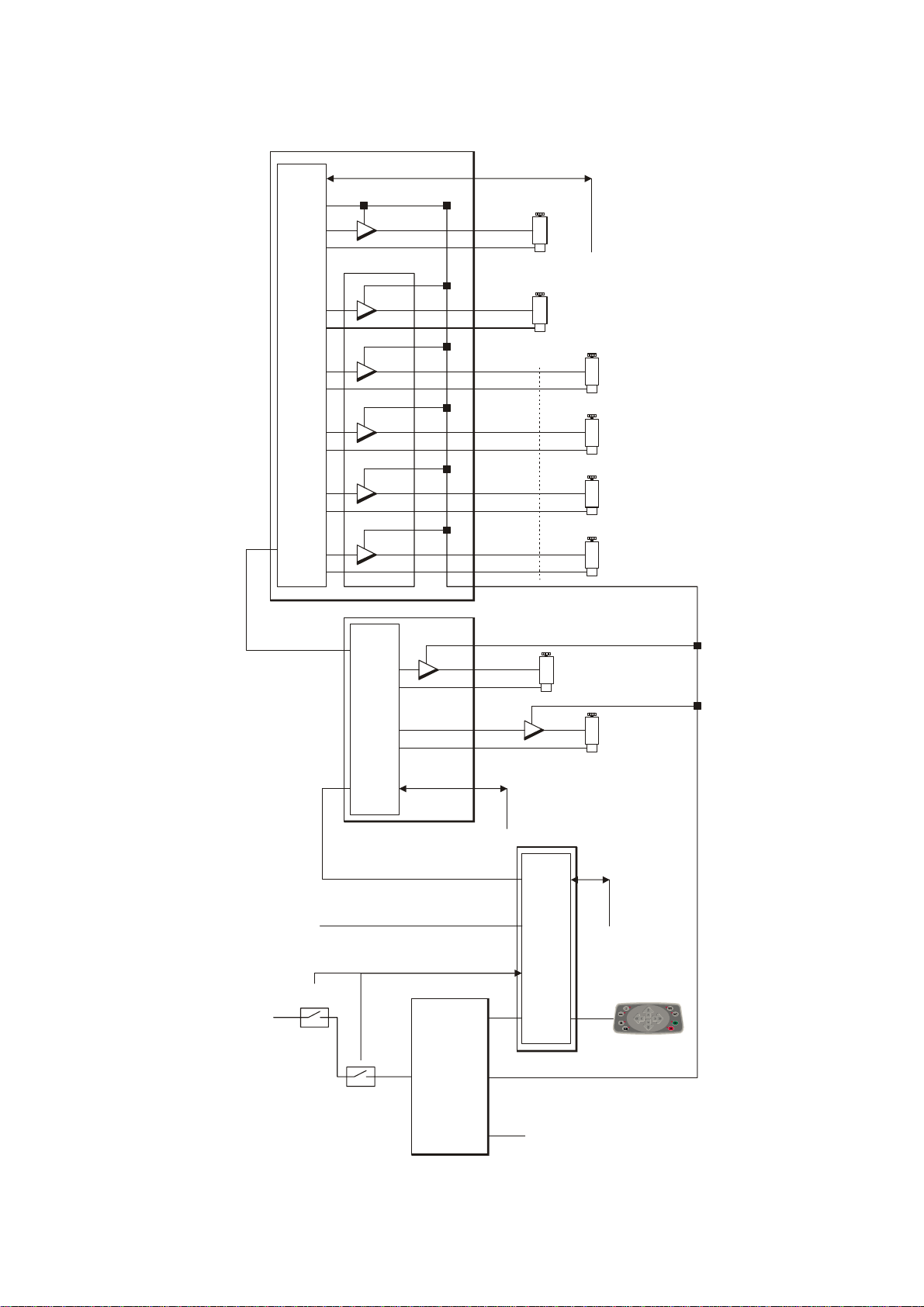
2.11.1 Safety system blocked schematic .............................................................................. 31
2.11.2 DynaGuard with LE20 controller, detailed description....................................... 31
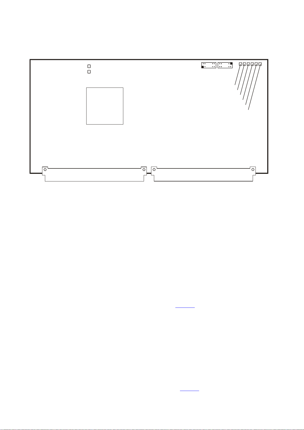
2.12 TROUBLESHOOTING THE GC900SM CONTROLLER ................................................................... 32
2.13 XE SYSTEM PARAMETERS.............................................................................................................. 33
2.13.1 System id definitions....................................................................................................... 33
2.13.2 Tool id definitions.............................................................................................................. 33
2.13.3 Tool series id definitions................................................................................................. 34
2.14 MOTOR /ENCODER SPECIFICATIONS.......................................................................................... 35
3. SIGNAL LISTS ................................................................................................................................. 36
3.1 SIGNALS TO/FROM CU-MODULES................................................................................................ 36
4. CABLES................................................................................................................................................ 36
4.1 XE10/I-XE10 WITH LE20 SAFETY RELAY................................................................................. 36
5. XE WITH XL-REGISTER.............................................................................................................. 37
6. XE WITH I-CUT (I-XE)............................................................................................................... 37
7. HOW TO... PROCEDURES .......................................................................................................... 38
7.1 INSTALLATION ................................................................................................................................38
7.2 MAINTENANCE................................................................................................................................38
7.3 TRAVERSE BEAM /X-CARRIAGE FIXTURE ON XXE32/54......................................................... 38
7.4 MOTOR ASSEMBLY ON XE10/I-XE10......................................................................................... 39
7.5 HOW TO REMOVE X1/X2 COVERS,XXE10................................................................................ 40
7.6 HOW TO REMOVE X1/X2 GEARBOX,XXE10.............................................................................. 42
7.7 HOW TO REMOVE X1/X2 COVERS,I-XE32/54........................................................................ 43
7.8 HOW TO REMOVE THE Y-CARRIAGE COVER................................................................................. 44
7.9 HOW TO REMOVE THE Z-AXIS MOTOR AND SCREW................................................................... 45
7.10 GEAR ADJUSTMENT,BASIC PRINCIPLES ...................................................................................... 47
7.11 MOTOR PINION ADJUSTMENT........................................................................................................ 48
7.11.1 General.................................................................................................................................. 48
7.11.2 Y-axis motor pinion.......................................................................................................... 49
7.11.3 X-axis motor pinion, XE10 and i-XE10..................................................................... 49
7.12 RACK PINION ADJUSTMENT........................................................................................................... 50
7.12.1 Adjusting X-axis rack pinion on xXE10 .................................................................... 50
7.12.2 Adjusting X-axis rack pinion on xXE32/54.............................................................. 52
7.12.3 Adjusting Y-axis rack pinion on xXE10/32/54....................................................... 53
8. ELECTRICAL DRAWINGS, INDEX......................................................................................... 54
9. MECHANICAL DRAWINGS, INDEX....................................................................................... 55
10. APPENDIX – VACUUM ZONES............................................................................................ 57
11. APPENDIX – HOUR COUNTER AND MAINTENANCE TRACKING..................... 58

Technical Manual Kongsberg XE/i-XE
4
11.1 HOUR COUNTER.............................................................................................................................. 58
11.2 DISPLAY OF HOUR COUNTER IN THE ABOUT DIALOG:............................................................... 58
11.3 MAINTENANCE TRACKING.............................................................................................................. 59
11.4 MAINTENANCE WARNING DIALOG ................................................................................................ 60
11.5 MAINTENANCE REMINDER ............................................................................................................. 60
12. APPENDIX – FRICTION LEVEL MEASUREMENT....................................................... 61
©
Copyright 2009 Esko-Graphics Kongsberg AS, Norway
All rights reserved. This material, information and instructions for use contained herein are the property of Esko-
Graphics Kongsberg AS. There are no warranties granted or extended by this document. Furthermore Esko-Graphics
Kongsberg AS does not warrant, guarantee or make any representations regarding the use, or the results of the use
of the system or the information contained herein. Esko-Graphics Kongsberg AS shall not be liable for any direct,
indirect, consequential or incidental damages arising out of the use or inability to use the system or the information
contained herein.
The information contained herein is subject to change without notice. Revisions may be issued from time to time to
advise of such changes and/or additions.
No part of this system may be reproduced, stored in a data base or retrieval system, or published, in any form or in
any way, electronically, mechanically, by print, photoprint, microfilm or any other means without prior written
permission from Esko-Graphics Kongsberg AS.
This document supersedes all previous dated versions.
Correspondence regarding this publication should be forwarded to:
Global Support
Esko-Graphics Kongsberg AS
Kirkegårdsveien 45
N-3601 KONGSBERG

Technical Manual Kongsberg XE/i-XE
5
2.System description
2.1 Kongsberg XE/i-XE tables, an overview
Operator
Panel
Carriage
Cutting TableFront End PC
N
e
t
w
o
r
k
Input Program File
MAP, HPGL,DXF
MCU SCU
X1 YX2
TCU
MPU
CAN
RS232C
I
0
The Cutting System consists of:
•Base
•Table top
•Traverse
•Carriage running along the traverse
•Tool Head mounted on the carriage
•Operator panel
•GC900SM controller
•System Software
The GC900SM controller consists of:
•Main Power Unit (MPU) located beneath the table top
•3 Control Unit boards:
−Main Control Unit (MCU) located beneath the Operator Panel
−Servo Control Unit (SCU) located at the X1 side of the traverse
−Tool Control Unit (TCU) located inside the carriage
•Amplifiers for motor control
The GC900SM controller is connected to the Front End PC through a serial line.
Normally, the Front End PC is connected to a host computer (server) through a
network connection.
The following controller related applications are available on the Front End PC:
•XE-Guide system software for ordinary table running.
•HWT900sm test program for table and tool adjustment and fault diagnostic.

Technical Manual Kongsberg XE/i-XE
6
•SYSLOADMPC program for loading new/upgraded software into the GC900SM
controller.
2.2 The Front End PC
For the system to run correctly, the Front End PC must be configured as follows:
2.2.1 Hypertreading
•Hypertreading must be disabled. This setting is available from PC boot setup /
performance menu. ( Press F2 while the PC is started ).
•The operator must have “Administrator privileges”. This setting is available from Control
Panel/User Account.
2.2.2 Power save
Any power save and screen save settings should be carefully examined. Functions
switching off the hard disk drive, system standby or hibernate should be disabled.
2.3 XE and i-XE tables, what is the difference?
We have tried to build these two models as equal as possible. The major differences
are:
XE i-XE
Gears X/Y
See datasheets for
speed data.
Standard gear High speed gear
Operator panel, Power
on/off switch and
Emergency switch
Mounted inside the front
cover on the table Mounted inside the
operator stand aside for
the table
2.4 Working areas
Working
area XE10/i-XE10 XE32/i-XE32 i-XE54
( Y x X ) 800 x 1100 mm
31 x 43 “ fixed size 1300 x 1620 mm
51 x 63 “ fixed size 1600 x 3050 mm
63 x 120 “ fixed size

Technical Manual Kongsberg XE/i-XE
7
2.5 Table positions
Working Area
800 x 1100 mm
31 x 43 inches
Vacuum Area
110 (4.3)
125 (4.9)
135 (5.3)
157(6.2) 172(6.8) () = inches
170(6.7)
1190(46.9)
185(7.3)
19
5
(
7
.
7
)
1558(61.3)

Technical Manual Kongsberg XE/i-XE
8
2.6 The GC900sm Control System
MPU
PC
Mains On/Off
Emergency
MCU
SCU
TCU
T2 Tool Rotation
T1 Tool u/d ( Reciproc. motor )
T2 Tool u/d ( Reciproc. motor )
T1 Tool Rotation
Z
Y
CU id
Tool Id T1/T2
Zero Detect Y
Tool Up Sns T1/T2
Material Detect
Fan Control
Warning Lamp
CU id
Zero Detect X1/X2
Sheet feeder control
Vacuum reverse
CU id
Servo On
Vacuum On
Vacuum area select
Safety system control
Power off / Emergency stop sns
e
e
e
e
e
e
e
e
X1
X2
Photocell safety
Servo Power
6/12A
6/12A
6/12A
3/6A
3/6A
3/6A
3/6A
3/6A
5x3/6A
CAN
CAN
48V DC mon
GC900sm Blocked schematic

Technical Manual Kongsberg XE/i-XE
9
2.6.1 MPC800 Board components and settings
LED1
LED2 RS232-2
U12U13
Debug ( BDM )
+5V
+2.6V
+3.3V
+5VExt
+15V
-15V
11
2.6.2 Main Power Unit (MPU)
Location: Hinged inside the front base frame.
Connections: For a schematic on how to connect, see chapter ‘Electrical
drawings’.
Description: The Main Power Unit contains power supplies in addition to
control relays for servo power and vacuum pump(s).
2.6.3 Main Control Unit (MCU)
Location: Beneath the operator panel (Picture)
Connections: The MCU board is connected to the MCU Signal Distribution
board. All external devices are connected to connectors on the
Signal distribution board.
For a schematic on how to connect, see chapter ‘Electrical
drawings’.
Description: This module handles communication to the Front-End PC and
acts as the master control unit in the system. This unit will
receive data from the PC, decode and send messages to the
Servo Control Unit and the Tool Control Unit.
The Operator Panel is connected directly to the MCU board via
the Signal Distribution board (Picture).

Technical Manual Kongsberg XE/i-XE
10
Servo and vacuum on/off is controlled from MCU.
In addition to the MCU board, one System id – board is
mounted on the MCU SDB board inside the MCU unit.
2.6.4 Servo Control Unit (SCU)
Location: Mounted outside the X1 carriage (Picture)
Connections: The SCU board is connected to the SCU Signal Distribution
board. All external devices are connected to connectors on the
Signal distribution board.
For a schematic on how to connect, see chapter ‘Electrical
drawings’.
Description: Performs servo control for X and Y-axes. Encoder feedback
from X1 and X2 is fed directly into this module. The analogue
output from the SCU module is connected to the 6/12 A
amplifiers for X1 and X2. The SCU module controls the
following DI/DO signals:
♦Zero reference for X1 and X2 provided by magnets located
inside the X - rails and sensors located on the X1/X2
carriages.
♦Photocell safety circuitries for Emergency stop brackets.
On i-XE, sheet feed and vacuum reverse is controlled by SCU.
2.6.5 6/12 A amplifier for X1 / X2 / Y
Location: The 6/12 A amplifier for X1 is located inside the SCU unit.
(Picture)
The 6/12 A amplifier for X2 is located in a separate box inside
the X2 carriage. (Picture)
The 6/12 A amplifier for Y is located inside the TCU unit
mounted on the Y carriage. (Picture)
Connections: For a schematic on how to connect, see chapter ‘Electrical
drawings’.
Description: Amplifiers for X1, X2 and Y motors
2.6.6 Tool Control Unit (TCU)
Location: Located inside the Y carriage (Picture)
Connections: The TCU board is connected to the TCU Signal Distribution
board. All external devices are connected to connectors on the
Signal distribution board.
For a schematic on how to connect, see chapter ‘Electrical

Technical Manual Kongsberg XE/i-XE
11
drawings’.
Description: Performs servo control for Z and Tool Rotation. Encoder
feedback from Y, Z and Tool Rotation is fed directly into this
module.
The analogue output from the TCU module is connected to 6/12
A amplifier for Y, and the 3/6 A amplifiers for Z and Tool
Rotation. The Reciprocating knife is controlled using one
analogue output channel and a 3/6A amplifier.
The TCU module controls the following DI/DO signals:
♦Zero reference for Y provided by one magnet located inside
the Y - rail and a sensor located on the Y carriage.
♦All tool related signals.
In addition to the TCU board, one 6/12 A amplifier board and
one 5x3/6A amplifier board is mounted on the TCU SDB board
inside the TCU unit.
2.6.7 5x3/6 A amplifier board
Location: The 5x3/6 A amplifier board is located inside the TCU - unit
mounted on the Y carriage (Picture).
Connections: For a schematic on how to connect, see chapter ‘Electrical
drawings’.
Description: This board contains 5 similar 3/6 A amplifiers. Provides motor
control for Z-axis and all tool motors, as Tool rotation,
Reciprocating knife, Tool selection and Tool depth control.
2.6.8 CAN-Communication
MCU SCU TCU
SDB SDB SDB
P1mc P1sc P2sc P1tc
07 07 07 07
03 03 03 03 CAN+
CAN-
S2 S2 S2
CAN network

Technical Manual Kongsberg XE/i-XE
12
A CAN network is used to communicate between the CU-modules. The network
protocol is according to CAN specification 2.0.
A twisted pair, connected as illustrated in the figure makes the network.
A terminating resistor, 124 Ω, is required in each end of the network cable. The
terminating resistor is available on the CU-board by connecting terminal S2 on the
Signal Distribution board.
ToC

Technical Manual Kongsberg XE/i-XE
13
2.7 GC900SM Power System
2.7.1 Mains
The GC900SM controller is prepared for the following voltages:
115V + 10%
230V + 10%
The voltage setting is made inside the MPU cabinet:
•The +24 V power supply is wide range; no setting for input voltage is
necessary.
•Configure the servo power transformer according to the actual voltage. See
chapter Electrical drawings, drawing ‘El schematic MPU with DynaGuard LE20’
for information about correct settings.
Two power supplies are located inside the MPU cabinet, generating +24V and +48V.
+24V is used for
•Power to the CU modules
•Tool control
+48V is used for
•Power to servo motor amplifiers
•Reciprocation knife motor.
Switching relay for vacuum on/off is available through Otto Heil connector on the rear
side of MPU.
2.7.2 Adjusting +48V depending upon local voltage variations
To obtain maximum performance, it is important that the +48V is adjusted correctly.
The actual voltage is measured and displayed when the Direction check in HWT900SM
is running.
It is possible to modify the power supply +/- 10%.
The nominal voltage is 49V with no load. If the voltage is below 44V or above 54V,
the transformer should be modified.
For information about how to modify the +48V power supply, see the MPU drawings
listed above.
This diagram shows the nominal levels for the available power supply settings:

Technical Manual Kongsberg XE/i-XE
14
29V
36V
40V
44V
54V
60V
63V
Supply voltage
Servo Voltage
Transformerwindingmiddle
+10 %
-10 %
Servo is switched off..
150V
75V 170V
85V 190V
95V 210V
105V 230V
115V 250V
125V 270V
135V
2.7.3 Power Consumption
Description + 24 V
(mA)
MCU 240
SCU 300
TCU 300
Complete System, Servo Off 840
Max System, Servo On, No
movement 880
Max = Systems with Basic Tool Head

Technical Manual Kongsberg XE/i-XE
15
2.7.4 Power on CU-modules
The following voltages are available on each CU-module:
Voltage Purpose
+5V Supply to circuits inside the CU-module
+5Vext. Supply for external devices, as Standard Panel, encoders
+15V Supply for op.amps on the CU-module
-15V Supply for op.amps on the CU-module
As all these voltages are regulated, no adjustment is needed.

Technical Manual Kongsberg XE/i-XE
16
2.8 Traverse solution
X
Y
Y
X1
X2
Two servomotors, X1 and X2, control the traverse position. One Y-motor controls the
position of the Y-carriage.
The angle of the traverse beam is automatically adjusted to obtain minimum friction.
The proper angle is found during the execution of the ‘Register table size’ wizard.
Different from other Kongsberg tables, we do not change the angle of the traverse
beam itself when the angle of the machine is adjusted.
Angle adjustment is carried out as software controlled position compensation only.
X1
X2
No reason to worry if the traverse beam is
out of angle as shown at left.
Note: After any mechanical adjustment of the traverse, carriages or drives, an update
of the traverse movement and the angle should be completed.
After Power on, before the ‘Table Zero Sequence’ is carried out, go to ‘Option’, ‘Table’
and select ‘Register table size’. Now the register table size function will be carried out
as part of the table zero sequence.
Verify correct angle – complete the adjust angle wizard found in ‘Option’, ‘Table’.

Technical Manual Kongsberg XE/i-XE
17
2.9 Tool solution
2.9.1 The Tool Connection Board
The Tool Connection Board is a signal distribution board for all signals going to the
two tool positions T1 and T2.
The board is connected to the TCU Signal distribution board through the flat cable
P1TB and the motor cable P2TB.

Technical Manual Kongsberg XE/i-XE
18
2.9.2 PressCut knife tool, pressure controlled
Rot
A
e
e
The Z-axis motor moves the tool head
to a proper level and keeps a
constant height relative to the
tabletop (ttop.dat).
Excenter radius is 4 mm; the distance
between tool up and tool down is 4
mm.
Motor A provides ‘local’ tool up/down
and tool pressure.
Max downward knife pressure 7N.
Speed dependant tool pressure
control.
Prepared for KCxx knife types.
The tool pressure is automatically
adjusted.
2.9.3 Static knife tool – folded & corrugated
A
Rot e
Motor A provides tool selection.
The excenter radius is 10 mm; the
distance between tool selected and
tool not selected is 20 mm.
The Z-axis provides tool up/down.
Height control relative to the tabletop
(ttop.dat).
Different knife adapters allows for
different knife types.

Technical Manual Kongsberg XE/i-XE
19
2.9.4 Crease tool
A
Rot e
Motor A provides tool selection.
Excenter radius is 10 mm; the
distance between tool selected and
tool not selected is 20 mm.
The Z-axis provides tool up/down.
Height control relative to the tabletop
(ttop.dat).
This tool is available in two versions,
one prepared for ø15 mm and one
prepared for ø26 mm crease wheels.
2.9.5 VibraCut knife tool
A
Rot e
The Z-axis motor provides tool
up/down.
The Z-axis position is controlled
relative to the tabletop (ttop.dat).
Motor A provides knife reciprocation.
Different knife adapters allows for
different knife types.
A removable foot is available. The
foot solution is preferable when
cutting recycled materials.
The reciprocating frequency is
controlled from sw. The reciprocating
amplitude is +/-0.15 mm.

Technical Manual Kongsberg XE/i-XE
20
2.9.6 Hi-frequenc VibraCut knife tool
A
Rot e
The Z-axis motor provides tool
up/down.
The Z-axis position is controlled
relative to the tabletop (ttop.dat).
Motor A provides knife reciprocation.
Different knife adapters allows for
different knife types.
A removable foot is available. The
foot solution is preferable when
cutting recycled materials.
The reciprocating frequency is
controlled from sw. The reciprocating
amplitude is +/-0.6 mm.
2.9.7 Hi-force knife tool – folded & corrugated
Rot e
The Z-axis provides tool up/down.
Height control relative to the tabletop
(ttop.dat).
Different knife adapters allows for
different knife types.
Other manuals for Kongsberg XE
1
This manual suits for next models
9
Table of contents
Other Esko Cutter manuals

Esko
Esko Kongsberg XE10 User manual

Esko
Esko Kongsberg XL User manual

Esko
Esko Kongsberg XP User manual

Esko
Esko Kongsberg C series User manual

Esko
Esko Kongsberg V-Series User manual

Esko
Esko Kongsberg XN IPC 2.0 User manual

Esko
Esko Kongsberg XP User manual

Esko
Esko Kongsberg C series Specification sheet